Table of Contents
Advertisement
Quick Links
Advertisement
Table of Contents

Related Manuals for TierTime UP300D


Summary of Contents for TierTime UP300D
- Page 1 Tiertime UP300D User Manual www.tiertime.com...
-
Page 2: Table Of Contents
2. Unboxing..........................7 2.1 Unboxing the UP300D......................... 7 2.2 What’s in the box......................... 8 3. Introduction........................... 9 3.1 Main Parts of UP300D......................... 9 4. Printer Installation......................10 4.1 Install the Print Board....................... 10 4.2. Install the Software UP Studio 3.0...................11 4.3 Update the Touchscreen Firmware.................. - Page 3 9.5 Print Settings..........................36 9.5.1 Print Modes..........................37 9.6 Introduction to Print Parameters..................... 38 9.6.1. Slicer Settings......................... 39 9.6.2 Path............................43 9.6.3.Special............................45 9.6.4 Speed............................46 9.6.5 Temperature..........................47 9.6.6 Seams Settings......................... 47 9.6.7 Printer............................48 9.6.8 Extruder........................... 48 9.6.9 Script............................48 Chapter 10.
- Page 4 16.1 Replacing Nozzle:........................76 16.3 Extruder Maintenance......................77 16.3.3 Convergence Dual Extruder....................79 16.3.3 Releasing the heater block....................80 16.3.4 Remove/Replace Stepper Motor..................82 16.3.5 Remove the extrude block....................82 16.4 Unclogging Extruder........................83 16.4.1 Partial Blockage........................83 16.4.2 Completely Blockage......................84 16.4.3 Remove blockage at heater module..................84 16.5 Clean the Waste Tray......................
-
Page 5: Safety And Printing Environment
1. Safety and Printing Environment 1.1 Safety Precautions 1. The UP300D 3D printer requires the power adapter provided by the original manufacturer, otherwise the machine could be damaged or even cause fire. Keep the power adapter away from water and out of high temperature environments. -
Page 6: Printing Environment
Tiertime and its authorized resellers warrant to the original purchaser that this product is free from defects in material and workmanship. Tiertime or its resellers will for one year, at its option, repair or replace at no charge for parts and labor from the date you purchased the product from Tiertime or a reseller. -
Page 7: Unboxing
2. Unboxing 2.1 Unboxing the UP300D 1. Cut open the tape on the top of the cardboard box, and open the box from the top. 2. Take out the two boards on the top foam, and remove the top foam. -
Page 8: What's In The Box
One Perf Glass Board One Power Adapter One Power Cord Notice: All accessories may be subject to change without prior notice. If anything is missing, please contact your local distributor, or Tiertime’s global technical support center, which can be reached via support@tiertime.com. -
Page 9: Introduction
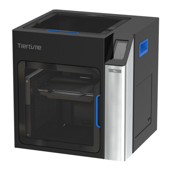
3. Introduction 3.1 Main Parts of UP300D 1. Dual Filter 7. Top Lid 2. Build Platform 8. Right Side Handle 3. Waste Tray 9. Heated Filament Chamber 4. Front Door 10. Power Switch 5. Touchscreen 11. Ethernet Socket 6. Front USB Port 12. -
Page 10: Printer Installation
4.1 Install the Print Board Find the “perforated print board”, slide the board onto the build platform and make sure to push the board all the way to the back. Plug in the power on the back of the UP300D. -
Page 11: Install The Software Up Studio 3.0
1. Download the UP300D Touchscreen Upgrade Program from https://www.tiertime.com/touchscreen-upgrade-program/ 2. Save the file to the root directory of the USB drive which comes with the UP300D, and make sure the file is named as “UP300D_x.x.x_update.tt” (Case sensitive), x.x.x being the version number. -
Page 12: Prepare Up300D For Printing
5. Prepare UP300D for Printing 5.1 Connectivity UP300D supports USB and other networking communications. For Wi-Fi, and Ethernet connection please refer to page 53-54, 66-68. 5.2 Auto Calibration Auto Calibration can be triggered from the touchscreen, or from Wand software when the printer is connected to a computer (refer to page 64). -
Page 13: Load The Filaments
1. 500g Tiertime PLA 2. 500g Tiertime PVA In order to achieve good consistency and print quality, we recommend use Tiertime filaments. The default print settings of UP Studio are optimized using Tiertime materials, so you can start printing confidently without adjusting any parameters. - Page 14 5. Go to touchscreen 1. Press Material 2. Press “Filament 1”Material 3. Press “ ” to extrude Button until it shows “PLA”, material. The machine will heat then press “+” button to up and buzz when start to increase material weight to extrude.
- Page 15 Filament 2 entry from the filament bay and the extruder head. On touchscreen, user should choose the correct support material that matches the main material. For PLA, the matching support material could be Tiertime PVA; for ABS, it should be the Tiertime Breakaway.
-
Page 16: First Print
-For more info on the Convergence Dual extruder please refer to page 73,77-82. -UP300D can also use LT (Low Temp) / HT (High Temp) Single Extruder for single material printing, for more info on printing with single material, please refer to page 72,75-76. -
Page 17: Load An Stl File
Layer thickness and nozzle diameter, the filament type for both extruders. For the material on the left, the filament 1(the main material), select PLA. For the one on the right, the filament 2, (the support material), select Tiertime PVA or PVA. 6.1.3. Load an STL file... -
Page 18: Auxiliary Support (A.s.)
STL loaded After the activation of the second extruder, once you load an STL, an Auxiliary Support will be automatically loaded to the software. The object list on the left of the software interface will show two entries, one is the STL, and the other is the Auxiliary Support with .AUX extension. - Page 19 6.1.5 Positioning the Auxiliary Support Move the Auxiliary Support pillar to a suitable location. a. First left click on the Auxiliary Support to select it, then click the “ ” move button. b. Right-click-drag the Auxiliary Support to an area not overlapping with the STL model. Alternatively user can adjust the location by using the key pad.
-
Page 20: Connect And Send Print Job To Printer
Ethernet, please refer to page 66-69. USB Connection Use the USB cable included, connect to one of your computers USB port and UP300D’s back side USB port (Type-B). Open UP Studio 3 on the computer, click the “ ” button (Print) to bring up the “Wand”... -
Page 21: Remove Printed Models
6.3 Remove Printed Models To remove the printed model from the print board of the UP300D, it is recommended to wear gloves for protection. Take out the print board with its front handle, use the scraper that comes with the machine to scrape the model off the print board starting from one corner of the model. -
Page 22: Printer Calibrations
7. Printer Calibrations The Printer calibrations in Tiertime Printers include the followings: 1. Nozzle Height Measurement 2. Platform Matrix Leveling (9-Point Compensation) 3. Vertical Calibration 4. Dimensional Calibration All of the above calibrations are software driven. The Nozzle Height Measurement and the 9-point Leveling Compensation are routine procedures initiated by users via either the UP Studio or the touch screen on the printer. -
Page 23: Nozzle Height Measurement
7.1 Nozzle Height Measurement Nozzle Height Value is the most important measurement of the printer as it determines how close the nozzle to the build platform when the printing starts. A good first layer adhesion is essential to a good print. In order to achieve the good first layer adhesion, the optimal distance between the nozzle and the print surface is very important. - Page 24 6. Use the height detector that comes with the machine to confirm the nozzle height value. User needs to put the sensor pad of the height detector under the nozzle and then use + / - buttons to adjust the nozzle to touch the sensor until the sensor gives a buzz sound. When the nozzle height is determined by the sensor, click “Apply Height”...
-
Page 25: Matrix Leveling (9-Point Compensation)
7.3 Matrix Leveling (9-Point Compensation) Tiertime Matrix Leveling can effectively reduce the adverse effects of tilt and uneven surface of build platform. The leveling will not affect the print's dimensional accuracy in contrary to other leveling methods. Its leveling mechanism is to first measure the platform heights at 9 different points and then use the values to generate a compensating raft that provides a flat and leveled build surface. -
Page 26: Auto Matrix Leveling Through Wand
7.3.1 Auto Matrix Leveling through Wand If your printer equips with touch screen, you can carry out the leveling process using the touch screen program. You can find the detail instructions on page 62. Using the Wand program, you can setup the leveling by following the steps below: 1. -
Page 27: Manual Calibration
7.4 Manual Calibration Although the Auto Calibration is the easiest way to calibrate the UP300D, some advanced users may prefer to the manual leveling process, which can provide the full control of the process and end up with more accurate result. - Page 28 Use the nozzle height detector (or a piece paper as the feel Click the “Next” button gauge) to determine the platform height at the measurement to save the current point. height reading and move to the next measurement point. Repeat the measurement for all 9 points then the software will calculate the compensation values for all the 9 points as well as the nozzle height value.
-
Page 29: Introduction To Up Studio 3 Package
8. Introduction to UP Studio 3 Package UP Studio 3.0 is the latest Tiertime Software package that work with Tiertime’s 3D printer helping the users to make 3D printing models. It includes two components: the UP Studio, an independent slicer and the Wand, the application hosting printer specific functions. -
Page 31: Introduction To The Up Studio, The Slicer
9. Introduction to the UP Studio, the Slicer 9.1 Interface Quick Set Bar Program Log Model Layout Buttons Print Preview View Slider Print Setting Switcher Command Field Model list 9.2 Quick Setting Bar Printer Model Layer Thickness Nozzle Diameter Extruder 2 Material Print Quality Extruder 1 Material Support Material (2) - Page 32 Preview the Slicing Results. The 3D files will be sliced but not saved. The slicing result will appear on the file list of left column. The “Print” button. Clicking this button will call out the “Wand” application. This button does not initiate printing.
-
Page 33: Support Editor
The support editing result will be shown on the model at real time. Support Types: There are three types of supports in Tiertime’s support generating algorithm. They are treated differently and can be edited separately. Support Generated 1. - Page 34 3. Point Support the “Tips” of Support features Support Parameters: Support Parameters Support List Support Preview View Options Support Angle The overhang angle threshold for support, overhangs less than this angle will not have support generated. Top Layer This determines the number of the interface layers between the support structure and the surface being supported.
- Page 35 Draft Angle = 0 Draft Angle = 50 Min. Area The area threshold of the support structure, the overhang surfaces with the area less then the threshold will not have the support structures generated. Min. Length The Length threshold for the edge support. The edges shorter than the threshold will not have the support structures generated.
-
Page 36: Print Settings
9.5 Print Settings - Click the Gear button to edit the current print setting. - Click the “Profile Name” to switch to the profile management. The default profile cannot be deleted. Users can create new profiles by copying existing profiles and edit upon the copy. Current Print Saved Print Profiles Profile... -
Page 37: Print Modes
9.5.1 Print Modes Print Setting Mode: Click the button to switch among Basic, Advanced, Expert modes. For the Basic Mode, the print setting is similar to the ones in the UP Studio 2. In the basic mode, although limited, the print settings are highly optimized with the essential print parameters with which users are able to get excellent print quality. -
Page 38: Introduction To Print Parameters
Please refer to the extruder settings for more information on this topic. For the most up-to-date details of print settings, please go to Tiertime knowledge base for details: https://support.tiertime.com/hc/en-us/sections/900000044383-UP-Studio-3... -
Page 39: Slicer Settings
Inner Outer Perimeter (Blue) Top Layers Perimeters (Green) Infill Support Top Layers Bottom Layers Support 9.6.1. Slicer Settings Term Unit Description Quality Layer Height Layer Height of a print. The bigger the value, the faster the printing speed and the lower of the print quality. Max. - Page 40 Height Range: 25-35mm Layer Height: 1.0 mm Height Range: 0-10mm Layer Height: 1.0 mm For the regions that are not defined by customized layer height, the default layer height setting will be applied. Customized layer height will override the adaptive layer function. ...
- Page 41 Bottom Layers Layers Set the number of bottom layers Min. Area The threshold area for top and bottom Expand Expand the area of top and bottom. Support Angle The angle threshold for the support structure. The larger the angle, the more support to be generated.
- Page 42 Mode Raft infill mode. Profile is for Tiertime printer only. The raft is generated by printers. The pattern is not visible at this stage. The other two options, hatch and offset, are for non-Tiertime printers. Tiertime machines cannot use these 2 options.
-
Page 43: Path
9.6.2 Path Term Unit Description Path Mode Profile/Perimeter Infill Density The density of the infill pattern. 100%=solid infill, 0%=no infill Support Density The density of the support column. The larger the value, the more stable the support structure is, but consume more material and more difficult to remove. - Page 44 Fill Angle The starting angle of infill pattern Angle Increase Fill Angle increase after each layer Angle Increase = 30 Layer 1 Layer 2 Layer 3 Final Pattern Angle Increase = 45 Layer 1 Layer 2 Layer 3 Final Pattern Angle Increase = 90 Layer 1 Layer 2...
-
Page 45: Special
Support Angle 2 Angle of sparse support infill Perim/Infill Overlap Overlap ratio between Perimeter and Infill Bottom Overlap Overlap ratio between Perimeter and infill for the bottom layer 9.6.3.Special Special Options Fill Mode Fill = Perimeter+infill+top/bottom Shell = Perimeter+top/bottom (no infill) Vase = Perimeter only (no infill, no top/bottom) Perimeter Gap The max gap on perimeters. -
Page 46: Speed
Thin Wall Features that are not printable due to too small or too thin will be retained and forcefully printed. Dimensional accuracy may be compromised when checked but all features are preserved. Hole Shrink (Only applied to vertical holes on a part, expanding small holes to counter the hole shrink effect.) Max. -
Page 47: Temperature
9.6.5 Temperature Temperature Tune Perimeters Tune Set increase/decrease of nozzle temperature when printing Perimeters ℃ Infill Tune Set increase/decrease of nozzle temperature when printing Infill ℃ Support Tune Set increase/decrease of nozzle temperature when printing Support ℃ Raft Tune Set increase/decrease of nozzle temperature when printing Raft ℃... -
Page 48: Printer
9.6.7 Printer Printer Configuration Manufacturer Brand/Producer of the printer Model ID Printer Model Origin X-coordinate for origin Y-coordinate for origin Z-coordinate for origin Build Volume X-axis range Y-axis range Z-axis range Acceleration Perimeters mm/s Acceleration for Perimeters Infill mm/s Acceleration for Infill Support mm/s Acceleration for Support... - Page 49 Infill Start M42: Switch I/O Pin; e.g. M42 P15 S0 or S1, port 15, s0 = off, s1 = on M73: Set Build Percentage M80: ATX Power On Infill End M81: ATX Power Off M82: Set Extruder to Absolute Mode M83: Set Extruder to Relative Mode Support Start M92: Set Axis_Steps_Per_Unit...
-
Page 50: Chapter 10. Material Library (Mat Lib) And Custom Materials
Chapter 10. Material Library (Mat Lib) and Custom Materials Filament Select a Material Profile. Type Material Type: can only choose from preset types Material ID A unique number for matching materials. E.g. The TSK file’s material ID must match printer’s material ID in order to print. Manufacturer Name of Material manufacturer. -
Page 51: Chapter 11. Part Sub-Setting
Chapter 11. Part Sub-setting Part Sub-setting is a feature that a 3D geometry of an object can be used to define a region in the 3D model in which different print settings can be applied. Save Mesh Change color Add Child Model Basic Info Delete Model Transparent View... -
Page 52: Optimize On X-Y Plane
Height point range Click the gear button to modify the print profile for the height range. chain button to link or unlink from the part profile. Start cross button to delete the child profile. point Setting child profiles is the same way of setting the main profile. However some settings are not available in the child profiles, e.g. - Page 53 100% ( child (main model) model The support and raft generation does not apply to the child models.
-
Page 54: Wand - The Printer Hosting Software
12. Wand - the Printer Hosting Software 12.1 Wand Interface 1. Printer Showing the serial number in default or the printer name of the connection connected machines. Users can select “Auto Connect” option in the menu on the top right button. Click + to connect or click X to disconnect the printer. - Page 55 Click to move the print head along the Z axis at a small step. Click to move the print head along the Z axis continuously until it reaches the desired position. 5. Extruder : The current material in use for the extruder. Settings : The current material weight left in spool which is loaded to the extruder.
-
Page 56: Wi-Fi Connection
Wi-Fi network that you set for the UP300D. 12.3 Ethernet Connection Plug in an ethernet cable into the LAN port on the back of UP300D. Once the connection is established, a LAN icon will appear on the touchscreen. -
Page 57: Editing Network Configuration
12.4 Editing Network Configuration When connected to a network, click the edit button will bring the detail network setting page. Use may edit the settings here to suit their network requirements. -
Page 58: Touchscreen Introduction
Tiertime UP300D Touchscreen consists of two sections, the Printer Status Bar and the Main Menu. 13.1 Printer Status Bar The Printer Status Bar is at the top of the UP300D Touchscreen, which is easy for you to monitor the printer’s status regularly. Nozzle1... -
Page 59: Main Menu
13.2 Main Menu There are six buttons in the Main Menu: Material, Print, Calibrate, Information, Config, and Initialize. The following table lists all the information of the icons in the Main Menu and summarizes the actions associated with the each icon. Main Menu Icon Description Name Icon... -
Page 60: Material
UP300D supports Dual Extrusion. In the Material section, it includes the settings for two filaments. One is for the main filament, “Filament 1”, which is highlighted with “Blue” color. The other filament is the support filament, “Filament 2”, which is... - Page 61 Name Icon Description To take out the filament inserted in the extruder with the preset temperature. Click the Withdraw button. The UP arrow on the button Withdraw will start moving upwards, indicating the extruder is heating up. The extruder will start pushing the filament out once the temperature reaches the melting temperature with a beep.
-
Page 62: Print
13.4 Print In the Print section, you can start a print job or manage the print jobs that are currently in the print queue or have finished. There are two print lists: The Print Job Current List have the print jobs that have been assigned to the printer. - Page 63 Print Job History List The Print Job History List contains all the print jobs that have finished. Tap the Print Job Name in the list to view the detail print settings. You can add the print job back to the Current Print Job List. The Clear button will erase the entire history print list.
- Page 64 Start a Print Print Job Information Printing Paused Printing Print Description Name Icon Description Pause the on-going print job. Pause Resume the paused print job. Resume To stop the on-going print job completely. Stop To extrude the inserted filament. Extrude To withdraw the inserted filament.
-
Page 65: Calibrate
Value Box, and then tap the Value Box to move the nozzle to the value you set in the Value Box. Nozzle Height is the current printer’s nozzle height. The default value for the nozzle height for each Tiertime printer has been set as 0mm before leaving factory floor safety reasons. -
Page 66: Information
13.6 Information In this section, the program displays all the information of your printer. The information on this page is not editable. Model: The Model Name of your printer. S.N.: Your printer’s ID set by the manufacturer. It will be required if you contact the customer service. -
Page 67: Config
13.7 Config Config section contains five parameters, and the Network Settings . Name: The printer’s name. You can change it using the 34° C | 37° C UP Studio software. The default name is the printer’s Serial Number. N am e 252212 Sound: Toggle the click sound while using touchscreen. -
Page 68: Network Connection
This section includes Ethernet Network Settings and Wi-Fi Network Settings. Ethernet Network Settings: 1. Plug an Ethernet cable to the LAN socket at the back of UP300D. 2. The Ethernet connection Status icon should appear in the Printer Status Bar. - Page 69 Network Settings Icon Description The following descriptions also applies for Wi-Fi network settings. Icon Description Name The printer is connected with Network Ethernet. Type/ The name of the connected Name Wi- Fi network. Toggle the static IP option to Static edit the following settings for the static IP.
-
Page 70: Wi-Fi Network Connection And Settings
3. Find the desired Wi-Fi Network’s name in the list below. 4. Tap the Wi-Fi name to connect the Wi-Fi Network. 5. The UP300D is connect to the Wi-Fi Network successfully, when the red exclamation mark disappeared, an interlock and Information icon appears. - Page 71 Wi-Fi Network Settings Description Name Icon Description Toggle the option to allow the printer to connect Wi-Fi Networks to Wi-Fi networks. Choose the name of the network to connect to Wi-Fi Name T i erti m e-01 Once this icon appears next to the Wi-Fi Connection network name, it indicates the printer has been Status...
-
Page 72: Initialize
13.10. Initialize The printer requires initialization before printing. The Material, Calibration and Print buttons on the Main menu of the touchscreen will be grayed out before the printer is properly initialized. Click Initialize and confirm the printer will start initializing by clicking “√”. -
Page 73: Chapter 14. Print Boards
Chapter 14. Print Boards There are two build plates in the UP300D package. 14.1 Perf Glass Boards The Perf Glass Board is the one with many small holes on one side. The perforated surface has the strongest surface adhesion when used with raft setting. It is made for printing materials with high shrinkage ratio that tend to warp during printing and frequently used in conjunction with the HT (High Temp) extruder. -
Page 74: Chapter 15. Extruders
Chapter 15. Extruders UP300D has following extruder options: 1. LT Single Extruder (Included) 2. Convergence Dual Extruder (Included, and installed on the machine) 3. HT Single Extruder (Optional) *HT=high temperture, LT=low temperature 15.1 Single Extrusion Print Heads HT Single Extruder There are 2 types of single extruders available: HT type and LT type. -
Page 75: Convergence Dual Extruder
Heater Block Part Cooling Nozzle Convergence Dual is a patent-pending technology designed by Tiertime. The Convergence hotend has two channels “converge” at one nozzle opening. The two channels can extrude different materials alternately. Since the two extrusions share a single nozzle, there is no need for the nozzle alignment calibration. The two... -
Page 76: Chapter 16. Maintenance
Chapter 16. Maintenance 16.1 Replacing Nozzle: 1. Wear heat resistance gloves and use the included nozzle wrench. 2. The nozzle must be removed while the extruder is heated up to near printing temperature. When extruder is heated up, use the nozzle wrench to unscrew the nozzle. -
Page 77: Extruder Maintenance
16.3 Extruder Maintenance 16.3.1 Single Extruder Replacement 1. Withdraw any filament currently loaded into the extruder. 2. Remove the cover for FFC cable. 3. Unplug the extruder FFC cable. 4. Use the the M4 Allen key included in the accessories to unscrew the screw on the left side of the extruder to remove the extruder, and then position the replacement extruder in the right place, tighten the screw, and plug in the extruder cable. - Page 78 3. Remove heater module and heat sink. 1. Remove the 2xM3 screws holding the heat sink to 2. Remove 2xM2.5 screws, remove the printed PCB extruder motor. mount and release the PCB and unplug the heater cable. 3. Remove the M2.5 screw...
-
Page 79: Convergence Dual Extruder
16.3.3 Convergence Dual Extruder Dismount the extruder. Unplug the CFC cable on the extruder. Remove the M4 screw on the right side of the extruder. Unplug the 2 cables of the fans. Pull off the extruder cover. -
Page 80: Releasing The Heater Block
Remove 2xM2.5 hex screws to remove the smaller fan. Remove 4xM3 hex screws above the hotend module. Unplug the 2x cables of heater modules and cut the zip tight to separate the heater module. 16.3.3 Releasing the heater block Remove the mounting block from heater module. - Page 81 Remove the 2xM3 hex screws that press hold the heater block onto the heat sinks. Remove the 4xM2.5 hex screws to release the PEEK filament entrance (the brownish part). This will expose the PTFE tube inside the heater block. Remove the 2xM2.5 hex screws from the wind shield so that the heat sink separate into two parts.
-
Page 82: Remove/Replace Stepper Motor
16.3.4 Remove/Replace Stepper Motor The stepper motor’s gearbox may worn out over time. The stepper motor can be replaced individually. User may also use this method to clean the extrusion gear, as overtime the gear may be covered with debris of plastics. Remove the 2xM3 hex screws and unplug the corresponding motor cable from extruder PCB. -
Page 83: Unclogging Extruder
Pull out the extruder block, then turn it for so that is it is vertical and remove it from the extrusion mechanism. The filament and extrusion gear will be expose for maintenance. 16.4 Unclogging Extruder. When the extruder fails to extrude filament, very likely a blockage or partial blockage is formed somewhere in the channel of the hotend. -
Page 84: Completely Blockage
Partial blockage usually takes place at nozzle, so replacing a new nozzle will likely solve the problem. If under extrusion persists after the nozzle is changed, the issue could be related to printing parameters. 16.4.2 Completely Blockage A complete blockage prevents filament to be extruded. The symptoms could be filament grinding at extruder wheel or the extruder produces clunky noises. -
Page 85: Clean The Waste Tray
3. If the pushing from both side are not working, users can try to remove the heater module from the extruder. Please refer to the previous pages of this chapter. Remove the PTFE tubes in the heater module and then heat up the heater block by using a torch light/bunsen burner/alcohol lamp/stove flame. -
Page 86: Dual Filtration System
16.6 Dual Filtration System UP300D has a Dual Filtration System includes HEPA Filter and the Activated Carbon Filters. Both of the filters are located inside the build chamber, circulating the air internally to reduce the micro particles generated during the 3D printing process. -
Page 87: Chapter 17. Specification
Supported Materials UP Fila ABS, ABS+, PLA , TPU and more Filament Diameter 1.75mm Filament Spool Compatibility 500 - 1000g Tiertime Print Queue Pause to Change Filament Type Out of Filament Detection Compatible with 3rd party Materials Physical dimensions Machine Dimensions 500x523x460 mm (19.6″... -
Page 88: Chapter 18. Customer Service And Community
Chapter 18. Customer Service and Community Technical Support Email to support@tiertime.com Ticketing System Knowledge Base: https://support.tiertime.com User forum: https://forum.tiertime.com Facebook Group https://www.facebook.com/grou ps/205337203341609/ Facebook Page facebook.com/tiertime... - Page 89 Youtube Channel youtube.com/tiertime Twitter twitter.com/tiertimecorp Instagram instagram.com/tiertime...
Need help?
Do you have a question about the UP300D and is the answer not in the manual?
Questions and answers