Table of Contents
Advertisement
Quick Links
Advertisement
Table of Contents

Related Manuals for TierTime UP Plus 2


Summary of Contents for TierTime UP Plus 2
- Page 1 UP Plus 2 user manual version : 4.6.5...
-
Page 2: Table Of Contents
Table of Contents Precautions ....................... Printer Body illustration ................... Accessories ....................... Remove Shipping Clips ..................Install UP software .................... Initialization of Printer ..................Platform Calibrate: 1.Setting Nozzle Height ................. 2.Setting Compensation Values ..............Coarse manul platform leveling ............... Print A Model ....................Software Interface .................... -
Page 3: Precautions
Precautions 1. UP Plus 2 3D printer requires power adapter provided by original manufacturer. Otherwise machine could be damaged or even cause fire hardzard. Please also keep the power adapter away from water and high temperature. 2. During printing, the nozzle of the printer will reach 260... - Page 4 UP Plus 2 Specification Printing Technology MEM (Melted Extrusion Manufacturing) Build Volume 140 x 140 x 135mm (W x H x D) 5.5" x 5.5" x 5.3" Print Head Single, Modular for easy replacement. Z-Resloution 0.15/0.20 /0.25 /0.30 /0.35 /0.40 mm...
-
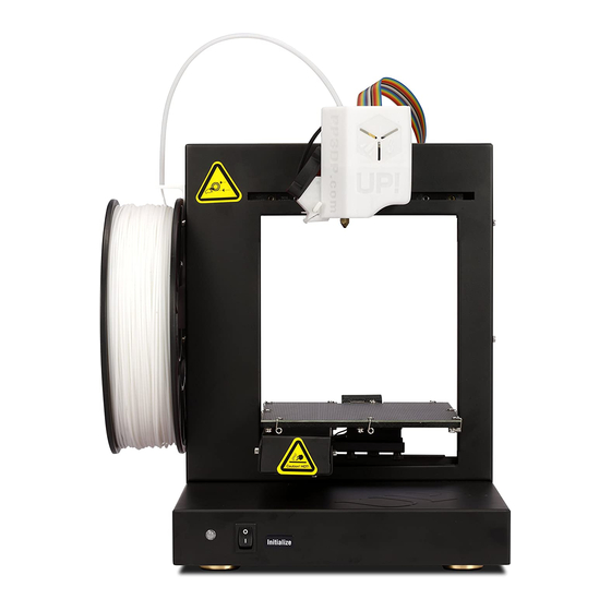
Page 5: Printer Body Illustration
Printer Body illustration Filament Guiding Tube Spool Holder Print Head Filament Spool Print Platform Initialization button Cable Clip Nozzle height Detection Device Power Button 3.5mm interface USB Interface Power Interface... -
Page 6: Accessories
Accessories Perf Board USB Cable Spool Holder Power Adapter Gloves Filament ABS Filament Plier Guiding Tube Blots and Nuts Hex Keys Shovel Nozzle height Detector Nozzle Wrench 3.5mm Cable *If anything is missing please contact your local distributor or support@pp3dp.com. -
Page 7: Remove Shipping Clips
Remove Shipping Clips User may keep the shipping clips in case the printer need to be shipped in the future. Install Perf Board and Spool Holder Spool holder hook on the left side of Put on the platform Hold the Perf Board with the machine. -
Page 8: Install Up Software
Install the Filament Guiding Tube Top View Put the filament spool on the spool holder and insert the filament through the guiding tube and into the print head. Install UP software 1.Go to support section of www.pp3dp.com to download the latest version of UP Software. 2. -
Page 9: Initialization Of Printer
Two ways of initialization: 1. UP Plus 2 can be initialized by clicking initialization option in the menu which is shown above. 2. The printer has an Initialization Button in front of the machine shown in the picture below. - Page 10 Software Interface Quick functional Buttons Main Menu Status Bar Display the statsu of printer and Print Plate software. - left mouse click and hold, moving mouse to adjust camera angle. - Right mouse click and hold, moving mouse to move print plate. -Mouse wheel could scale the print plate view.
- Page 11 (eg. slightly tilted platform) and this could cause warping of prints or even complete failure. Fortunately UP Plus 2 has automatic platform calibration and automatic nozzle height detection functions. By using these 2 functions, the calibration process could be finished quickly and easily.
- Page 12 There are 3 screws under the platform of UP Plus 2. These screws can be fastened or loosened to adjust the leveling of the platform. In "3D Print" - "Maintainance" window, user can move the print head to 5 difference postions on the platform.
- Page 13 Automatic Nozzle Height Detection After autoleveling, remove the platform leveling device unplug the 3.5mm cable from it. Plug the cable into the 3.5mm interface of the Nozzle Height Detection Device. Hit "Nozzle Height Detection" in the "3D Print" Menu. The platform will rise slowly until the nozzle height detection device hit the nozzle.
- Page 14 Loading a Model Click "Open" Choose your model. Loaded model on the print plate. Click "Print" to open the print preview window .
- Page 15 Prepare for Printing Make sure printer switched on and connected to computer. Select Main Menu - 3D Print - Maintainance. Click New Spool and choose ABS and input filament weight. Click "Extrude" button, the print head will start to heat up, within 5 minutes its temperature will reach 260 C, then printer will...
- Page 16 Click "OK" to start printing. The program will first slice the m o d e l i n to G co d e a n d t h e n transfer the data to the printer. Af te r s en di n g th e d at a , the program will suggest the amount of material and time needed for the model in a pop up window.
- Page 17 Pause of Print Job During printing, the machine could be paused through maintainence interface. When the printer is idle, there is a "Table heat 1 hr" button under "Stop All" button. Press this button will keep platform heated for one hour.
- Page 18 Moving Model Click the model to select. Click Move button. Select distance value to in the drop dwon menu. Choose an axial direction to move the model. Drag model with mouse on XY-plane: Press and hold Ctrl key, mouse left click and hold the target model, now the model could be dragged around on XY-plane.
- Page 19 Rotate Model Click to select model. Click Rotate button. Choose angle of rotation in the drop dwon menu. Choose an axial direction to rotation the model. Scale Model Click to select model. Click Scale button. Choose the scaling value in the drop down menu.
- Page 20 Duplicate Model Click to select model. After selection, right click to open menu In the insert copy m e n u, s e l e c t t h e number of copy for duplication. Right click menu also contain unload function. Either choose a specific model to unload or unload all.
-
Page 21: Printing Parameters
Printing Parameters 1. Z-resolution: Thickness of each printed layer, the lower the value, the more details will be generated. 2. Part: Angle: Determine the range of dense support generation. Surface: Choose the how many layers will be made for bottom of the model. 3. -
Page 22: Annotation Of Printing Parameters
Annotation for printing parameters Dense (support) Infill Dense (support) Support Surface Dense (support) Print Platform Raft Suppot Range: Support Range: < 30 < 80 Dense: Solid support structure ensure the surface being supported retain its shape and surface finish. Infill: The inner structure of the printed object, the density of infill could be adjusted. -
Page 23: Repair Model
Repair Model UP software contains model repair function, can be used to fix simple defects. If the model contains defects, eg.holes. The sofware will highlight the part with red. A f t e r s e l e c t i n g t h e model, choose Edit - Fix to repair the model. -
Page 24: Calibration For The Correct Dimension
Calibration for the Correct Dimension If prints are too big or too small or skewed, user could re-calibrate the printer to print in correct dimension. The method is to print a calibration model, measure its dimension and feedback to the software. L o a d a n d p r i n t t h e calibration model: C : \ P r o g r a m F i l e s \ U P \... -
Page 25: Printing Techniques
Printing Techniques 1. Ensure accurate nozzle height. Nozzle height value too low will cause warping, too high will crash nozzle to platform causing damage and clogging. It is possible to manually fine tune nozzle height value at "maintenance" and "print preview" panels. User could try to adjust the nozzle height value plus or minus 0.1 - 0.2mm base on previous results. -
Page 26: Troubleshooting
Please use UP filament. 4. For some model, if PLA consistently cause problem, switch to ABS. 1. Install the printer driver correctly. Cannot detect the printer 2. Check for defective USB cable. 3. Restart printer and Computer Contact technical support: Others support@tiertime.net... - Page 27 1.Setting Nozzle Height Setting nozzle height, actually, is not setting the nozzle itself as UP Plus 2's print head does not move in the Z-axis. Here the nozzle height we are refering to is a platform height value, at this height, the platform will be just touching the nozzle (thus "nozzle height").
- Page 28 Protocol for setting nozzle height: Open the calibration interface and press the UP key, note the current height value, stop the platform at about 115. Put print paper on platform. Initialize printer Hit the "5" button. Nozzle will go to the center of the platform. Raise the platform until it is just touching the nozzle.
- Page 29 Platform too high, nozzle Just right,could feel Platform too low, no i s p i n n i n g p a p e r o n to some resistance when resistance at all when the platform, Lower the moving the paper. moving paper, raise platfrom slightly.
- Page 30 2. Setting Compensation Values As shown in the left, when platform is at the "nozzle height", only part of the platform is touching the nozzle. Therefore we need to set compensation values for all other calibration points to inform the printer about the distance between nozzle and print sur face throughout the XY plane.
Need help?
Do you have a question about the UP Plus 2 and is the answer not in the manual?
Questions and answers