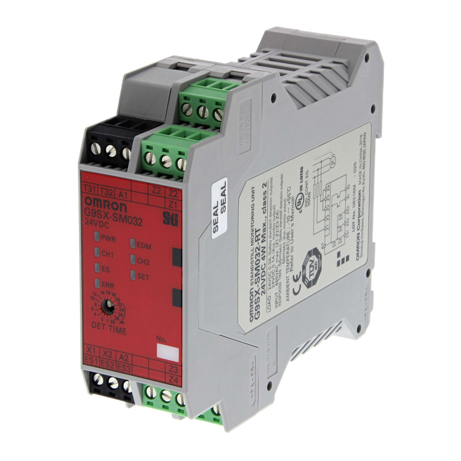
Omron G9SX-SM032 Series - Standstill Monitoring Unit Manual
- User manual (12 pages)
Advertisement
Introduction
Thank you for purchasing G9SX Standstill Monitoring Unit.
Please read and understand this manual before using the products. Keep this manual ready to use whenever needed. Only qualified person trained in professional electrical technique should handle G9SX.
Please consult your OMRON representative if you have any questions or comments. Make sure that information written in this document are delivered to the final user of the product.
Omron Corportion
EU Declaration of Conformity
OMRON declares that G9SX-SM□ is in conformity with the requirements of the following EU Directives:
EMC Directive 2004/108/EC
Machinery Directive 2006/42/EC
Standards
G9SX-SM□ is designed and manufactured in accordance with the following standards:
EN954-1 Category 4,
EN ISO13849-1:2008 Category 4 PL e,
IEC/EN61508 SIL3,
IEC/EN62061 SIL3,
IEC/EN61000-6-2,
IEC/EN61000-6-4,
UL508,
CAN/CSA C22.2 No.142
Precautions for Safe Use
Meanings of Signal Words
The following signal words are used in this manual.

Indicates a potentially hazardous situation which, if not avoided, will result in minor or moderate injury, or may result in serious injury or death.
Additionally there may be significant property damage.
Meaning of Alert Symbols
The following alert symbols are used in this manual.
 | Indicates prohibited actions. |
 | Indicates mandatory actions. |
Alert Statements


Serious injury may possibly occur due to breakdown of safety outputs.
Do not connect loads beyond the rated value to the safety outputs.
Serious injury may possibly occur due to loss of required safety functions.
Do not use G9SX-SM in the system where plurality of motors are driven by one inverter or contactor.
Serious injury may possibly occur due to loss of required safety functions.
Wire G9SX properly so that supply voltages or voltages for loads do NOT touch safety outputs accidentally or unintentionally.
Serious injury may possibly occur due to damages of safety outputs.
Apply protection circuitry against back electromotive force in case connecting inductive loads to safety outputs.
Serious injury may occur due to failure of safety functions. Operate the motor at rated G9SX-SM input frequency (120Hz) or less.
Serious injury may possibly occur due to loss of safety functions.
Use appropriate devices referring to the information provided below.
| Controlling Devices | Requirements |
| Guard Lock Safety-door Switch | Use approved devices with Direct Opening Mechanism complying with IEC/EN 60947-5-1, mechanical lock type and capable of solenoid coil 24VDC, less than 300mA. |
| Relay with forcibly guided contacts | Use approved devices with forcibly guided contacts complying with EN 50205. For feedback purpose use devices with contacts capable of switching micro loads of 24VDC, 5mA. |
| Contactor | To be able to detect an open failure of a contactor, use contactors with forcibly guided mechanism and connect the NC contact to the EDM input of G9SX. For feedback purpose use devices with contacts capable of switching micro loads of 24VDC, 5mA. If a contactor without a forcibly-guided mechanism is connected to EDM inputs through the NC contact, failure of the contactor will not be detectable. |
| Other devices | Evaluate whether devices used are appropriate to satisfy the requirements of safety category level. |
- Use G9SX-SM□ within an enclosure with IP54 protection or higher according to IEC/EN60529. Be sure to connect the encloseure to earth(PE).
- Incorrect wiring may lead to loss of safety function. Wire conductors correctly and verify the operation of G9SX-SM□ before using the system in which G9SX-SM□ is incorporated.
- Do not apply DC voltages exceeding the rated voltages, nor any AC voltages to G9SX-SM□.
- Use DC supply satisfying requirements below to prevent electric shock.
- DC power supply with double or reinforced insulation, for example, according to IEC/EN60950 or EN50178 or a transformer according to IEC/EN61558.
- DC supply satisfies the requirement for class 2 circuits or limited voltage/current circuit stated in UL 508.
- Apply properly specified voltages to G9SX-SM□ inputs.
Applying inappropriate voltages cause G9SX-SM□ to fail to perform its specified function, which leads to the loss of safety functions or damages to G9SX-SM□. - Auxiliary error outputs and auxiliary monitoring outputs are NOT safety outputs. Do not use auxiliary outputs as any safety output
Such incorrect use causes loss of safety function of G9SX-SM□ and its relevant system. - After installation of G9SX-SM□, qualified personnel should confirm the installation, and should conduct test operations and maintenance. The qualified personnel should be qualified and authorized to secure the safety on each phases of design, installation, running, maintenance and disposal of system.
- A person in charge, who is familiar to the machine in which G9SX-SM□ is to be installed, should conduct and verify the installation.
- G9SX-SM□ determines that motor stops when the standstill detection input voltage is predetermined value or less. According to the characteristic or load condition of motor, it may turn on safety detection outputs before motor stops completely. In that case, before operation, the qualified personnel should verify that risk of the rotation condition after output is acceptable.
- Perform daily and 6-month inspections for the G9SX-SM□. Otherwise, the system may fail to work properly, resulting in serious injury.
- Do not dismantle, repair, or modify G9SX-SM□. It may lead to loss of its safety functions.
- Use only appropriate components or devices complying with relevant safety standards corresponding to the required level of safety categories.
Conformity to requirements of safety category is determined as an entire system.
It is recommended to consult a certification body regarding assessment of conformity to the required safety level. - OMRON shall not be responsible for conformity with any safety standards regarding to customer's entire system.
- Disconnect G9SX-SM□ from power supply when wiring. Devices connected to G9SX-SM□ may operate unexpectedly.
- Be cautious not to have your fingers caught when attaching terminal sockets to the plugs on G9SX-SM□.
- Do not use in combustible gases or explosive gases.
- Driving voltage of the motor is impressed to the standstill detection inputs. Connect overcurrent protective equipment; fuse, circuit-breaker etc., (3A Max.) and tighten the wirings by rated tightening torque to the standstill detection inputs.
Precautions for Correct Use
- Handle with care
Do not drop G9SX-SM□ to the ground or expose to excessive vibration or mechanical shocks. G9SX-SM□ may be damaged and may not function properly. - Conditions of storage and usage
Do not store or use in such conditions stated below.- In direct sunlight
- At ambient temperatures out of the range of -10 to 55 ℃
- At relative humidity out of the range of 25% to 85% or under such temperature change that causes condensation.
- In corrosive or combustible gases
- With vibration or mechanical shocks out of the rated values.
- Under splashing of water, oil, chemicals
- In the atmosphere containing dust, saline or metal powder.
G9SX-SM□ may be damaged and may not function properly.
- Mounting
Mount G9SX to DIN rails with attachments (TYPE PFP-M, not incorporated to this product), not to drop out of rails by vibration etc. especially when the length of DIN railing is short compared to the widths of G9SX.
Do not use G9SX-SM□ at altitudes over 1,000 meters - Following spacing around G9SX should be available to apply rated current to outputs of G9SX and for enough ventilation and wiring:
- At least 25 mm beside side faces of G9SX.
- At least 50 mm above top face of G9SX and below bottom face of G9SX.

- Wiring
- For model G9SX-SM□
Use the following to wire to G9SX-SM□.
- Solid wire: 0.2 to 2.5mm2 AWG24 to AWG12
- Stranded wire (Flexible wire): 0.2 to 2.5mm2 AWG24 to AWG12
Strip the cover of wire no longer than 7mm.
- For model G9SX-SM□-RT (with screw terminals)
Tighten each screw with a specified torque of 0.5 to 0.6N・m, or the
G9SX-SM□ may malfunction or generate heat.
- For model G9SX-SM□
- Use cables with length less than 100m to connect to standstill detection Inputs and EDM input respectively.
- Driving voltage of the motor is impressed to the standstill detection input and there is a possibility that a high level of noise is superimposed. The line of the standstill input must be separately installed from other signal lines.
- Set the time duration of Standstill detection time to an appropriate value that does not cause the loss of safety function of system.
- Tuning mode in User configuration is only for adjusting the Standstill determining time. In Tuning mode, auxiliary monitor output is enable however Safety Standstill detection outputs are not enabled. After the tuning is complete, be sure to change from Tuning mode to Monitoring mode for actual operation.
- Safety standstill detection outputs are only for controlling a guard lock safety-door switch with mechanical lock. They can not be used as safety outputs to drive contactors, or to control a guard lock safety-door switch with solenoid lock.
- To determine safety distance to hazards, take into account the delay of safety standstill detection outputs caused by the response time
- Start entire system after more than 5s have passed since applying supply voltage to all G9SXs in the system.
- G9SX-SM□ may malfunction due to electro-magnetic disturbances.
Be sure to connect the terminal A2 to ground. - This is a class A product. In residential areas it may cause radio interference, in which case the user may be required to take adequate measures to reduce interference.
- Devices connected to G9SX-SM□ may operate unexpectedly. When replacing G9SX-SM□, disconnect it from power supply.
- Adhesion of solvent such as alcohol, thinner, trichloroethane or gasoline on the product should be avoided. Such solvents make the marking on G9SX-SM□ illegible and cause deterioration of parts.
- Connectable motor
AC induction motors can be connected to the G9SX-SM□. Servo motors cannot be connected.
When a motor with AC240V or more is used, connect neutralpoint of the power supplay to earth. - G9SX-SM□ does not have motor fault detective function or motor protective function. For motor protection, use designated external protective devices.
- For use with inverter
The dynamic break setting time should be set to 30 seconds or shorter. Otherwise, the G9SX-SM□ may detect a disconnect fault of the wiring.
Also in the following cases, the standstill detection function may not properly work even while the motor is in standstill.- An inverter with a large output residual voltage is used, and the contactor connected in serial with the inverter is in the ON state.
- The inverter is executing the auto tuning function.

Suitability for Use
OMRON shall not be responsible for conformity with any standards, codes, or regulations that apply to the combination of the products in the customer's application or use of the product.
Take all necessary steps to determine the suitability of the product for the systems, machines, and equipment with which it will be used. Know and observe all prohibitions of use applicable to this product.
NEVER USE THE PRODUCTS FOR AN APPLICATION
INVOLVING SERIOUS RISK TO LIFE OR PROPERTY WITHOUT ENSURING THAT THE SYSTEM AS A WHOLE HAS BEEN
DESIGNED TO ADDRESS THE RISKS, AND THAT THE OMRON PRODUCT IS PROPERLY RATED AND INSTALLED FOR THE INTENDED USE WITHIN THE OVERALL EQUIPMENT OR SYSTEM.
OMRON Corporation (Manufacturer)
Shiokoji Horikawa, Shimogyo-ku, Kyoto, 600-8530 JAPAN
OMRON EUROPE B.V. (Importer in EU)
Wegalaan 67-69, NL-2132 JD Hoofddorp THE NETHERLANDS PHONE 31-2356-81-300 FAX 31-2356-81-388
OMRON SCIENTIFIC TECHNOLOGIES INC.
6550 Dumbarton Circle, Fremont CA 94555-3605 U.S.A PHONE 1-510-608-3400 FAX 1-510-744-1442
OMRON ASIA PACIFIC PTE. LTD.
438A Alexandra Road # 05-05/08,
Alexandra Technopark Singapore 119967 SINGAPORE
PHONE 65-6-835-3011 FAX 65-6-835-2711
OMRON (CHINA) CO., LTD.
Room 2211, Bank of China Tower, 200 Yin Cheng Zhong Road,
PuDong New Area, Shanghai, 200120, China
PHONE 86-21-5037-2222 FAX 86-21-5037-2200
Note: Specifications subject to change without notice.

Documents / ResourcesDownload manual
Here you can download full pdf version of manual, it may contain additional safety instructions, warranty information, FCC rules, etc.
Download Omron G9SX-SM032 Series - Standstill Monitoring Unit Manual
Advertisement


Need help?
Do you have a question about the G9SX-SM032 Series and is the answer not in the manual?
Questions and answers