Table of Contents
Advertisement
Quick Links
Original instructions
Type G9SX-SM032-
Standstill Monitoring Unit
USER'S MANUAL
English
Thank you for purchasing G9SX Standstill Monitoring
Unit.
Please read and understand this manual before
using the products.
Keep this manual ready to use whenever needed.
Only qualified person trained in professional
electrical technique should handle G9SX.
Please consult your OMRON representative if you
have any questions or comments.
Make sure that information written in this document
are delivered to the final user of the product.
© OMRON Corporation 2008-2020 All Rights Reserved.
EU Declaration of Conformity
OMRON declares that G9SX-SM is in conformity with
the requirements of the following EU Directives:
EMC Directive 2014/30/EU
Machinery Directive 2006/42/EC
Standards
G9SX-SM is designed and manufactured in accordance
with the following standards:
EN ISO13849-1:2015 Category 4 PL e,
IEC/EN61508 SIL3,
IEC/EN61000-6-2,
UL508,
CAN/CSA C22.2 No.142
Safety Precautions
Meanings of Signal Words
The following signal words are used in this manual.
Indicates a potentially hazardous situation
which, if not avoided, will result in minor or
moderate injury, or may result in serious
WARNING
injury or death.
Additionally there may be significant
property damage.
Meaning of Alert Symbols
The following alert symbols are used in this manual.
Indicates prohibited actions.
Indicates mandatory actions.
3080529-6 F
IEC/EN62061 SIL3,
IEC/EN61000-6-4,
Alert Statements
Serious injury may possibly occur due to breakdown
of safety outputs.
Do not connect loads beyond the rated value to the
safety outputs.
Serious injury may possibly occur due to loss of
required safety functions.
Do not use G9SX-SM in the system where plurality of
motors are driven by one inverter or contactor.
Serious injury may possibly occur due to loss of
required safety functions.
Wire G9SX properly so that supply voltages or
voltages for loads do NOT touch safety outputs
accidentally or unintentionally.
Serious injury may possibly occur due to damages of
safety outputs.
Apply protection circuitry against back electromotive force
in case connecting inductive loads to safety outputs.
Serious injury may occur due to failure of safety functions.
Operate the motor at rated G9SX-SM input frequency
(120Hz) or less.
Serious injury may possibly occur due to loss of
safety functions.
Use appropriate devices referring to the information
provided below.
Controlling
Requirements
Devices
Use approved devices with Direct Opening
Guard Lock
Mechanism complying with IEC/EN 60947-5-1,
Safety-door
mechanical lock type and capable of solenoid
Switch
coil 24VDC, less than 300mA.
Use approved devices with forcibly guided
Relay with
contacts complying with IEC 61810-3 (EN 50205).
forcibly guided
For feedback purpose use devices with contacts
contacts
capable of switching micro loads of 24VDC, 5mA.
Use approved devices complying with IEC/EN
Contactor
60947-4-1 auxiliary contact linked with power
contact (mirror contact).
For feedback purpose use devices with contacts
capable of switching micro loads of 24VDC, 5mA.
Evaluate whether devices used are appropriate to
Other devices
satisfy the requirements of safety category level.
Suitability for Use
Omron Companies shall not be responsible for
conformity with any standards, codes or regulations
which apply to the combination of the Product in the
Buyer's application or use of the Product. At Buyer's
request, Omron will provide applicable third party
certification documents identifying ratings and
limitations of use which apply to the Product. This
information by itself is not sufficient for a complete
determination of the suitability of the Product in
combination with the end product, machine, system,
or other application or use. Buyer shall be solely
responsible for determining appropriateness of the
particular Product with respect to Buyer's application,
product or system. Buyer shall take application
responsibility in all cases.
NEVER USE THE PRODUCT FOR AN APPLICATION
INVOLVING SERIOUS RISK TO LIFE OR PROPERTY
OR IN LARGE QUANTITIES WITHOUT ENSURING
THAT THE SYSTEM AS A WHOLE HAS BEEN
DESIGNED TO ADDRESS THE RISKS, AND THAT
THE OMRON PRODUCT(S) IS PROPERLY RATED
AND INSTALLED FOR THE INTENDED USE WITHIN
THE OVERALL EQUIPMENT OR SYSTEM.
- 1 -
WARNING
Advertisement
Table of Contents

Related Manuals for Omron Sti G9SX-SM032 Series


Summary of Contents for Omron Sti G9SX-SM032 Series
- Page 1 © OMRON Corporation 2008-2020 All Rights Reserved. safety functions. Use appropriate devices referring to the information provided below. EU Declaration of Conformity OMRON declares that G9SX-SM is in conformity with Controlling Requirements Devices the requirements of the following EU Directives:...
-
Page 2: Precautions For Safe Use
(11) To determine safety distance to hazards, take into account the of conformity to the required safety level. delay of safety standstill detection outputs caused by the response (13) OMRON shall not be responsible for conformity with any safety time. standards regarding to customer's entire system. - Page 3 Functions Use the "Operation Preset switch" on the back side to select either Standard Configuration or User Configuration. The selected configuration mode is enabled at power-on. - Normally, please use Standard Configuration which is set as factory default. - If the Standstill determining time is found too long in the Standard Configuration mode, switch to User Configuration and adjust the Standstill determining time. ...
-
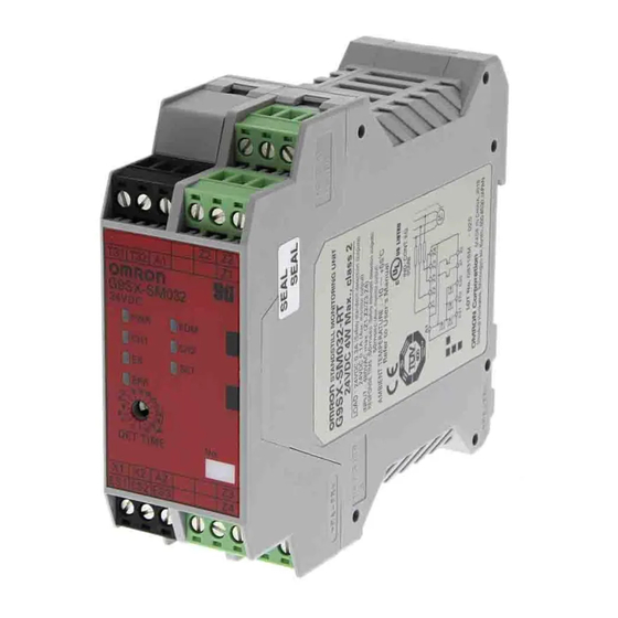
Page 4: Led Indicators
Appearance and Explanation of Each Parts Type G9SX-SM032- Power Supply(+) EDM input Standstill detection intput1 terminal Standstill determining time Preset switch Operation Preset switch Power Supply(-) Mode Preset switch Auxiliary Error output Auxiliary Monitor output Safety Standstill detection outputs terminal Standstill detection intput2 terminal LED Indicators Marking... -
Page 5: Internal Connection
Internal Connection Type G9SX-SM032- T31 T32 Z1 Z2 Standstill Standstill Power EDM input detection input 1 detection input 2 supply circuit Auxiliary Standstill output control outputs control *1 Internal power supply circuit is not isolated. *2 Standstill detection inputs are isolated respectively. *3 The Safety standstill detection outputs, ES1 - ES3, are internally redundant respectively. -
Page 6: Ratings And Specifications
Ratings and Specifications Ratings TYPE G9SX-SM032- Item Power Rated supply voltage 24VDC input Operating voltage range -15% to +10% of rated supply voltage Rated power consumption 4 W Max. (*1) Inputs Rated Input voltage Standstill detection input (Z1-Z2/Z3-Z4) (*2) 480VAC max.(120Hz max.)(*3) Standstill detection input : approx. -
Page 7: Application Examples
Application Examples G9SX-SM032(DC24V) <3-phase motor> + G9SX-AD322-T15(DC24V) <Guard lock Safety-door switch + Safety limit switch 2ch input / manual reset> Feedback loop KM1/KM2 +24V Z1 Z2 Z2 Z3 Z4 G9SX-SM032 Inverter Control circuit X1 X2 PLC etc. lamp Note1: This example is corresponding to category 4 (Stop category 1). - Page 8 G9SX-SM032(DC24V) <3-phase motor with Star-Delta wiring> + G9SX-BC202(DC24V) <Guard lock Safety-door switch + Safety limit switch 2ch input / manual reset> EDM input +24V Z1 Z2 Z2 Z3 Z4 G9SX-SM032 U2 V2 Control circuit U1 V1 X1 X2 PLC etc.
- Page 9 G9SX-SM032(DC24V) <3-phase motor> + G9SX-BC202(DC24V) <Emergency stop switch 2ch input / manual reset> + G9SX-GS226-T15(DC24V) <Guard lock safety-door switch + Safety limit switch 2ch input / manual reset> For protecting the motor against short-circuit due to incorrect wiring, etc., apply overcurrent +24V protective equipments;...
- Page 10 Wiring of inputs and outputs Terminal Signal Name Description of operation Wiring Name Power supply Connect the power source to the A1 and A2 Connect the power supply plus to the A1 terminal. terminals. input Connect the power supply minus to the A2 terminal. To turn on the Safety standstill detection outputs,both Standstill detection inputs must Connect Z1 and...
-
Page 11: Fault Detection
438A Alexandra Road # 05-05/08, Shiokoji Horikawa, Shimogyo-ku, Kyoto, 600-8530 Alexandra Technopark Singapore 119967 JAPAN SINGAPORE OMRON EUROPE B.V. (Importer in EU) PHONE: 65-6-835-3011 FAX: 65-6-835-2711 Wegalaan 67-69, NL-2132 JD Hoofddorp THE NETHERLANDS OMRON (CHINA) CO., LTD. PHONE: 31-2356-81-300 FAX: 31-2356-81-388...
Need help?
Do you have a question about the Sti G9SX-SM032 Series and is the answer not in the manual?
Questions and answers