Emerson Rosemount 3408 Quick Start Manual
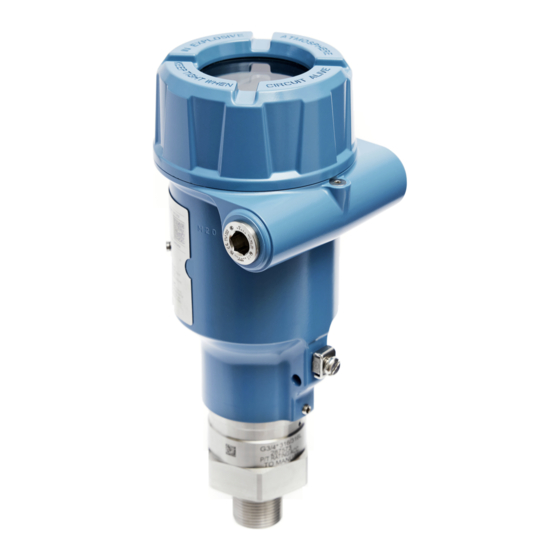
Level transmitter
Hide thumbs
Also See for Rosemount 3408:
- Reference manual (140 pages) ,
- Quick start manual (12 pages) ,
- Reference manual (104 pages)

Related Manuals for Emerson Rosemount 3408


Summary of Contents for Emerson Rosemount 3408
- Page 1 Quick Start Guide 00825-0100-4418, Rev AA September 2022 ™ Rosemount 3408 Level Transmitter Non-Contacting Radar...
-
Page 2: Table Of Contents
Contents About this guide...........................3 Confirm approval type........................5 Mount the process seal antenna....................6 Mount the lens antenna....................... 8 Mount the ATAP lens antenna....................10 Rotate the transmitter housing....................13 Prepare the electrical connections....................14 Connect wiring and power up.....................17 Configuration..........................22 Emerson.com/Rosemount... -
Page 3: About This Guide
September 2022 Quick Start Guide About this guide This Quick Start Guide provides basic guidelines for the Rosemount 3408 Level Transmitter. Refer to the 3408 Reference Manual for more instructions. Safety messages WARNING Failure to follow safe installation and servicing guidelines could result in death or serious injury. - Page 4 Restrict physical access by unauthorized personnel to protect end users’ assets. This is true for all systems used within the facility. CAUTION Hot surfaces The flange and process seal may be hot at high process temperatures. Allow to cool before servicing. Emerson.com/Rosemount...
-
Page 5: Confirm Approval Type
September 2022 Quick Start Guide Confirm approval type For hazardous locations transmitters labeled with multiple approval types: Procedure Permanently mark the checkbox of the selected approval type. Figure 2-1: Label with Multiple Approval Types Quick Start Guide... -
Page 6: Mount The Process Seal Antenna
Quick Start Guide September 2022 Mount the process seal antenna Mount the flanged version Procedure 1. Lower the transmitter into the nozzle. Note Be careful not to scratch or otherwise damage the PTFE sealing. Emerson.com/Rosemount... - Page 7 September 2022 Quick Start Guide 2. Tighten the bolts and nuts (see Table 3-1). Note • Re-tighten after 24 hours and again after the first temperature cycle. • Check at regular intervals and re-tighten if necessary. Torque specifications The conditions used for the calculation are: •...
-
Page 8: Mount The Lens Antenna
1. Apply anti-seize paste or PTFE tape on threads according to your site procedures. 2. Mount the transmitter on the tank. Example • (A) Threaded fitting • (B) Threaded flange 46 mm / 50 mm Note Be careful not to scratch or otherwise damage the PTFE sealing. Emerson.com/Rosemount... - Page 9 September 2022 Quick Start Guide Mount on BSPP (G) threaded connections Procedure 1. Place a suitable gasket on the tank nozzle. Example • (A) Threaded fitting • (B) Threaded flange 2. Mount the transmitter on the tank. 46 mm / 50 mm Note Be careful not to scratch or otherwise damage the PTFE sealing.
-
Page 10: Mount The Atap Lens Antenna
The antenna extension must be fitted to the transmitter to comply with open air requirements. Figure 5-1: Antenna Extension Mount the bracket Prerequisites Mount the bracket so that it is not susceptible to vibration. Procedure 1. Mount the bracket to the pipe/wall. Example 14 mm Emerson.com/Rosemount... - Page 11 September 2022 Quick Start Guide 2. Mount the adapter. 14 mm 3. Secure the transmitter to the adapter. 50 mm Quick Start Guide...
- Page 12 Quick Start Guide September 2022 Mount on 1½-in. BSPP (G) threaded connections Procedure 1. Place a suitable gasket on the tank nozzle. Example • (A) Threaded fitting • (B) Threaded flange 2. Mount the transmitter on the tank. 50 mm Emerson.com/Rosemount...
-
Page 13: Rotate The Transmitter Housing
September 2022 Quick Start Guide Rotate the transmitter housing To improve field access to wiring or to better view the optional LCD display: Procedure 1. Loosen the set screw. H2.5 mm 2. Rotate the transmitter housing to the desired location, and then retighten the set screw. -
Page 14: Prepare The Electrical Connections
Transmitter housing The most effective grounding method is direct connection to earth ground with minimal impedance. There are two grounding screw connections provided (see Figure 7-1). Figure 7-1: Ground Screws A. Internal ground screw B. External ground screw Emerson.com/Rosemount... - Page 15 September 2022 Quick Start Guide Cable shield grounding Make sure the instrument cable shield is: • Trimmed close and insulated from touching the transmitter housing. • Continuously connected throughout the segment. • Connected to a good earth ground at the power supply end. Figure 7-2: Cable Shield A.
- Page 16 U E (Vdc) 15.6 17.6 Wiring diagram ® Figure 7-4: 4-20 mA/HART Communication A. Handheld communicator B. Approved IS barrier (for Intrinsically Safe installations only) C. HART modem D. Load resistance (≥250 Ω) E. Current meter F. Power supply Emerson.com/Rosemount...
-
Page 17: Connect Wiring And Power Up
September 2022 Quick Start Guide Connect wiring and power up Procedure Verify the power supply is disconnected. 2. Remove the cover. 3. Remove the LCD display (if fitted). 4. Remove the plastic plugs. Quick Start Guide... - Page 18 Identification of thread size and type: ½-14 NPT M20 x 1.5 6. Connect the cable wires. 0.3 in. (8 mm) Note When connecting a flexible (stranded) conductor, use a small screwdriver to press down and hold the terminal connection open. 7. Ensure proper grounding. Emerson.com/Rosemount...
- Page 19 September 2022 Quick Start Guide 8. Tighten the cable gland. Apply PTFE tape or other sealant to the threads. Note Make sure to arrange the wiring with a drip loop. 9. Seal any unused port with the enclosed metal plug. Apply PTFE tape or other sealant to the threads.
- Page 20 Verify the cover jam screw is completely threaded into the housing. H2.5 mm b) Attach and tighten the cover. Note Make sure the cover is fully engaged. There should be no gap between the cover and the housing. Emerson.com/Rosemount...
- Page 21 September 2022 Quick Start Guide c) Turn the jam screw counterclockwise until it contacts the cover. Note Required for explosion-proof/flameproof installations only. H2.5 mm d) Turn the jam screw an additional ½ turn counterclockwise to secure the cover. 12. Connect the power supply. Quick Start Guide...
-
Page 22: Configuration
Rosemount Radar Master Plus. Related information Emerson.com/RosemountRadarMasterPlus 9.2.1 Download AMS Device Configurator AMS Device Configurator is a software for configuration of Emerson field devices using FDI technology. Procedure Download the software at Emerson.com/AMSDeviceConfigurator. Confirm correct device driver Procedure 1. - Page 23 Wireless configuration via Bluetooth technology 9.5.1 Download the AMS Device Configurator Procedure Download and install the app from your app store. Related information Emerson.com/AMSDeviceConfigurator ® 9.5.2 Configure via Bluetooth wireless technology Procedure 1. Launch AMS Device Configurator. 2. Click on the device you want to connect to.
- Page 24 Quick Start Guide September 2022 ® Bluetooth UID and key You can find the UID and key on the paper tag attached to the device, and on the display unit. Figure 9-1: Bluetooth Security Information UID: KEY: Emerson.com/Rosemount...
- Page 25 September 2022 Quick Start Guide Quick Start Guide...
- Page 26 Quick Start Guide September 2022 Emerson.com/Rosemount...
- Page 27 September 2022 Quick Start Guide Quick Start Guide...
- Page 28 For more information: Emerson.com © 2022 Emerson. All rights reserved. Emerson Terms and Conditions of Sale are available upon request. The Emerson logo is a trademark and service mark of Emerson Electric Co. Rosemount is a mark of one of the Emerson family of companies.
Need help?
Do you have a question about the Rosemount 3408 and is the answer not in the manual?
Questions and answers