MSA PrimaX Operating Manual
Gas transmitter
Hide thumbs
Also See for PrimaX:
- Instruction manual (64 pages) ,
- Operating manual (58 pages) ,
- Quick start manual (3 pages)

Related Manuals for MSA PrimaX


Summary of Contents for MSA PrimaX
- Page 1 Operating Manual PrimaX Gas Transmitter / Software Version V1.18 Order No.: 10115083/05 MSAsafety.com...
- Page 2 Method" - appendixes to Pattern Approval Certificate of Measuring instrument, valid in the countries of use. The Declaration of Conformity can be found under the following link: https://MSAsafety.com/DoC. MSA is a registered trademark of MSA Technology, LLC in the US, Europe and other Countries. For all other trademarks visit https://us.msasafety.com/Trademarks.
-
Page 3: Table Of Contents
Safety and Precautionary Measures to be Adopted MSA Permanent Instrument Warranty Description Identifying the Unit Overview Installation Mechanical Installation Electrical Installation 3.2.1 Electrical Connection - PrimaX P 3.2.2 Electrical Connection - PrimaX I Operation Startup Menu Sequence Calibration Maintenance and Info Password... - Page 4 Cable Lengths and Cross-sections Performance Specifications List of Detectable Gases Sensor Response to Interferants PrimaX P List of Combustible Gases and Vapours detectable with Catalytic Sensor P/N 10112716 Approvals Marking, Certificates and Approvals according to the Directive 2014/34/EU (ATEX) and National Standards...
- Page 5 10.2 Calibration Errors 10.3 Error Codes 10.4 Timeout 10.5 Mechanical Installation 10.6 Wiring Diagrams PrimaX...
-
Page 6: Safety Regulations
The signal of the transmitter can be used in combination with MSA control units for further actions in safety or non safety applications, e. g. MSA SUPREMA, Gasgard XL, 9010/9020. - Page 7 [LOC]. This function shall be used for -standalone applications according to ATEX requirements. • Catalytic sensor: If the PrimaX is operated in combination with a control unit and [LOC] is deactivated on the PrimaX, the control unit has to ensure the latching after the measuring range was exceeded. •...
-
Page 8: Msa Permanent Instrument Warranty
Failure to follow these warnings can result in serious personal injury or death. MSA Permanent Instrument Warranty Warranty Seller warrants that this product will be free from mechanical defect or faulty workmanship for •... -
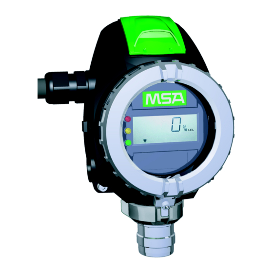
Page 9: Description
PrimaX I The PrimaX I is a gas transmitter with a plastic enclosure. It is available as a general purpose version [not intended for hazardous area] or intrinsically safe version. Both versions are designed for a detection of toxic gases or oxygen. - Page 10 • a detachable backplate for installation on a wall or on a pipe The device operates with a 4 – 20 mA output signal. Figure 2 Exploded View (PrimaX P) Terminal for power connection Sensor Keypad with cover...
- Page 11 Detection of toxic gases Detection of oxygen Detection of combustible gases The device operates with a 4 – 20 mA output signal. As an optional feature additional modules are available for these configurations of PrimaX transmitter: Modules PrimaX P PrimaX I...
-
Page 12: Installation
When preparing the assembly, make sure that the mounting arrangement is correct for the particular device. Mechanical Installation Preparation To install the device, first remove the backplate. Undo Screws Unscrew the device. PrimaX... - Page 13 The straight edge of the backplate should be at the bottom. Attach the Device to the Backplate Attach the device to the top of the backplate. Fold down the device, till it is closed to the backplate. PrimaX...
-
Page 14: Electrical Installation
The power supply is defined as 24 VDC. If the input supply voltage at the terminal of the transmitter is less than 10 V, the device will shut down. The 24 V power supply shall fulfill the requirements for a PELV/SELV of EN 60950. Operating the PrimaX I version in hazardous areas requires an -intrinsically safe power supply. PrimaX... -
Page 15: Electrical Connection - Primax P
Power supply (+) 24 V DC 0 V DC (-) 4 – 20 mA (Signal) Isolated ground Figure 5 3-wire/4-wire connection - PrimaX P Unscrew the interlock between cover and bayonet joint of sensor. Unscrew the aluminum lid of the enclosure. Unplug the 4-way terminal block. -
Page 16: Electrical Connection - Primax I
Power supply (+), 24 V DC 4 – 20 mA (Signal) PrimaX I Power supply (+) 4 – 20 mA (Signal) Figure 7 2-wire connection - PrimaX I Remove plastic cover. It is bolted with 4 screws. Remove the 2-way terminal block. It is located behind a plastic cover above the display. - Page 17 Insert cable for connection into the device. Connect cable to terminal. Use a 2-wire shielded cable. Tighten cable gland clamping nut, check that cable cannot move within the cable gland. Replace plastic cover, tighten the screws and secure the interlock. PrimaX...
-
Page 18: Operation
During startup a self-test is performed and the output signal is set to the service current [default 3.0 mA]. The following information is displayed: Display Test The display shows all segments. Note: The PrimaX P also shows all LEDs and afterwards the yellow LED is flashing during the startup procedure. Software Version The display shows the firmware version. -
Page 19: Menu Sequence
To navigate in the menu sequence, 4 buttons are available. In general: Press ENTER to get access to a menu sequence. Press UP or DOWN until the desired menu is displayed. Press ENTER to get access to a menu. Press ESC to cancel the process. PrimaX... -
Page 20: Calibration
Calibrate their sensors with the target gas. Do not use a surrogate gas for calibration. • After exposure to polar solvents, the sensor must be recalibrated using the target gas, independent of the calibration interval, and a gas/function check shall be performed 24 hours after calibration to verify sensor response and accuracy. PrimaX... - Page 21 60079-20-1. Local regulations may specify different LEL values; always ensure the correct values are used. It is recommended that the PrimaX zero is calibrated using clean air, free of measuring gas, and calibration gas of approximately 50 % of measuring range (comb. and TOX) in air of the gas being monitored. The recommended calibration gas for oxygen is 50% of measuring range, but for a measuring range 0-25 vol% , the device can be calibrated using 20.9 vol% O...
- Page 22 = 5 * t Test gas 90Gas depending on the test gas, see PrimaX Response time. Waiting for calibration gas After starting any calibration step, calibration gas [zero or test gas] must be applied until calibration step is finished. The calibration state is indicated by the output signal current and has to be monitored in case of manual calibration (→...
-
Page 23: Maintenance And Info
Only OX/TOX sensors can be exchanged with this menu. For COMB sensors with this menu only the initial calibration is initiated and the sensor life time is reset. Failure to follow this warning can result in serious personal injury or death. PrimaX... - Page 24 Sensors that are no longer required have to be disposed of in an environmentally compatible way. [M-06] - LCD/LED Test LCD and LED test [LED only available in PrimaX P]. All segments will be displayed and the LEDs will flash sequentially. Press ENTER and select menu 6.
- Page 25 NOTE: Before a reset of an over range (LOC) indication is done it shall be verified that the gas concentration is below full scale. Press ENTER and select menu 0. Press ENTER button. Enter password [→ chapter 4.5 Password]. Success message confirms that latched alarm is reset. PrimaX...
-
Page 26: Password
Bell 202 Frequency Shift Keying [FSK] standard to superimpose digital communication signals at a low level on top of the 4 - 20 mA. The HART Protocol provides two simultaneous communication channels: the 4 - 20 mA analog signal and a digital signal. The 4 - 20 mA signal communicates the primary measured PrimaX... -
Page 27: Electrical Installation
[in the case of a field instrument] using the 4 - 20 mA current loop. Additional device information is communicated using a digital signal that is superimposed on the analog signal. PrimaX is registered with the HART foundation and can be accessed at http://www.hartcomm.org/ The device is available with an optional HART module or a module with HART and Relays for alarm and failure. -
Page 28: Relays
4 Operation 4.7.3 Relays Figure 11 Location of Relay Relay Terminals Figure 12 Relay Terminals Alarm Relay Failure Relay Normally closed energised[NC] Normally closed energised[NC] Common [COM] Common [COM] Normally open energised[NO] Normally open energised[NO] PrimaX... -
Page 29: Relay Operation
12. Set alarm relay normally energized option with the UP or DOWN button. 13. Press ENTER button. 14. Set the failure relay delay with the UP or DOWN button. 15. Press ENTER button. 16. Set the failure relay normally energized option with the UP or DOWN button. PrimaX... - Page 30 Alarm/Failure relay delay time = 0s, no delay of output Failure relay normally energized = yes Changeable Parameters with HART For all parameters which can be changed over keypad see chapter 4.6 Changeable Parameters Values default minimum maximum Password 0000 0000 9999 Description PrimaX Long tag Message PrimaX...
- Page 31 In case of switched relays the device will go to the normal state when the related condition [non-latched alarm and/or fail] has been removed. LOC: The PrimaX Gas Monitor has been exposed to a high gas concentration [above the LEL], and the over- range condition still exists.
-
Page 32: Maintenance
See chapter 4.2 Menu Sequence. Remove Interlock Unscrew the socket head screw. Remove the interlock. Remove Bayonet Joint Turn the bayonet ring counter-clockwise. Remove the bayonet ring by pulling it down. PrimaX... - Page 33 5 Maintenance Replace Sensor Unplug the sensor carefully. Plug in the new sensor carefully. Replace the bayonet ring. Replace the interlock. PrimaX...
-
Page 34: Technical Data
6 Technical Data Technical Data Specifications PrimaX P PrimaX I aluminum enclosure plastic enclosure Enclosure flameproof intrinsically safe IP 67 ingress protection IP 66 ingress protection Dimensions in mm 220 X 162 X 100 220 X 162 X 81 [Height X Width X Depth] Weight 1.6 kg... -
Page 35: Cable Lengths And Cross-Sections
Catalytic Combustible Gas Sensor with 1.0 mm 420 m 4 – 20 mA Signal Output [4- wire Sensor] 1.5 mm 630 m 1.0 mm 1848 m Toxic Gases and Oxygen Sensors with 4 – 20 mA Signal Output [4- wire Sensor] 1.5 mm 2772 m PrimaX... -
Page 36: Performance Specifications
15% to 90 % rel. humidity Nominal orientation and vertical ± 15° (sensor downwards) orientation limits Deadband if enabled, measured values within the 0 ± 2% FS limits are indicated as zero (zero window) PrimaX... -
Page 37: List Of Detectable Gases
-40 – 70 °C 10 ppm Sulphur Dioxide [SO 50 ppm 20 ppm -20 – 50 °C 100 ppm * Extended range: The sensor extended temperature range is greater than the maximum specified in EN 60079-29-1. The requirement is met over the full temperature range. PrimaX... - Page 38 ≤ 10 s ≤ 18 s Methane ≤ 12 s ≤ 20 s ≤ 12 s ≤ 20 s Propane PrimaX Response time (with calibration cap, flow rate 1 l/min) Combustible Recovery time ≤ 24 s ≤ 85 s ≤ 24 s ≤ 85 s 1-Ethoxy-2-Propanol ≤...
-
Page 39: Sensor Response To Interferants
35 ppm NO <60 ppm 10 ppm <3 ppm Hydrogen [H 100 ppm C 10 ppm HCN 3 ppm 80 ppm 0.2 ppm AsH 5 ppm Cl 20 ppm HCN 7 ppm 0.7 ppm < +/- 0.1 ppm Hydrogen Chloride [HCl] 20 ppm H 10 ppm NO 100 ppm NO 45 ppm 60 ppm < +/- 0.5 ppm PrimaX... -
Page 40: Primax P List Of Combustible Gases And Vapours Detectable With Catalytic Sensor P/N 10112716
Sulphur Dioxide [SO <3 ppm -5 ppm PrimaX P List of Combustible Gases and Vapours detectable with Catalytic Sensor P/N 10112716 Relative response factors of tested gases with reference to Propane For the gases or vapours shown in the tables of this chapter the response curves have been tested according to EN 60079-29-1:2016. - Page 41 = 0.62 Propane calibration gas concentration being used = 0.89 Vol % Propane volume concentration for 100 % LEL = 1.7 Vol % Propane calibration gas concentration in % LEL = 52.4 % LEL Gas detector span setting = 52.4 % LEL x 0.62 = 32.5 % LEL PrimaX...
- Page 42 *) Response times are with a flow through adapter and a gas flow of 1 l/min Response factor defined by DEKRA Testing and Certification GmbH Response factor defined by MSA (not included in the EU-Type Examination Certificate BVS 10 ATEX E 009 X)
-
Page 43: Approvals
7 Approvals Approvals Marking, Certificates and Approvals according to the Directive 2014/34/EU (ATEX) and National Standards PrimaX P MSA Europe GmbH Manufacturer: Schlüsselstr.12 CH - 8645 Rapperswil-Jona Product: PrimaX P EU-Type BVS 10 ATEX E009 X Examination by DEKRA Testing and Certification GmbH (NB 0158) - Page 44 Table 2 of EN 60079-1:2014. For maintenance or repair contact the manufacturer. In case of using the PrimaX Ex-Sensor, the complete device type PrimaX P is in accordance to temperature class T6/T85°C, ambient temperature range -40°C ≤ Ta ≤ +40°C or to temperature class T4/T130°C, ambient temperature range -40°C ≤...
- Page 45 7 Approvals Accessories included in the type examination: Remote calibration adapter CalGard, part.-no. 10150921 Sensor Gard, part.-no. 10113033 Flow through adapter, part.-no. 10113031 Calibration cap, part.-no. 10112789 PrimaX I MSA Europe GmbH Manufacturer: Schlüsselstrasse 12 CH-8645 Rapperswil-Jona Product: PrimaX I...
- Page 46 7 Approvals Accessories included in the type examination: Remote calibration adapter CalGard, part.-no. 10150921 Sensor Gard, part.-no. 10113033 Flow through adapter, part.-no. 10113031 Calibration cap, part.-no. 10112789 PrimaX...
-
Page 47: Marking And Certificates According To Iecex
7 Approvals Marking and Certificates according to IECEx PrimaX P MSA Europe GmbH Manufacturer: Schlüsselstrasse 12 CH-8645 Rapperswil-Jona Product: PrimaX P IEC-Type Examination Certificate: IECEx BVS 10.0043 X IEC 60079-0:2011, IEC 60079-1:2014, Standards: IEC 60079-11:2011 IEC 60079-31:2013 Performance: none Gas:... - Page 48 Table 2 of EN 60079-1:2014. For maintenance or repair contact the manufacturer. In case of using the PrimaX Ex-Sensor, the complete device type PrimaX P is in accordance to temperature class T6/T85°C, ambient temperature range -40°C ≤ Ta ≤ +40°C or to temperature class T4/T130°C, ambient temperature range -40°C ?≤...
-
Page 49: Special Conditions For The Safe Use According To Atex And Sil Applications
LDM = Low Demand Mode HDM = High Demand or Continuous Mode SIL1 SIL2 SIL3 Structure 1oo1 Structure 1oo2 Depending on the selected configuration and the sensor version, the following safety-relevant parameters have to be considered while implementing the safety loop: PrimaX... - Page 50 In the case of an adjustment the sensitivity of the sensor has to be rechecked again after 24 hours. • If the appearance of catalytic poisons for the combustible sensor can not be avoided, the calibration interval has to be considerably reduced. PrimaX...
-
Page 51: Safety Relevant Parameters [40°C]
Nitrogen 7.5E- 1.6E- 5.6E- 1.2E- Dioxide 4237 2718 1518 86.8 63.1 12.0 Nitrogen 1.0E- 2.1E- 7.5E- 1.6E- Oxide 4877 3039 1839 1091 84.7 59.3 10.0 16.4 [NO] Oxygen 8.8E- 1.9E- 6.5E- 1.4E- 6044 3622 2422 1767 89.2 73.0 14.2 PrimaX... -
Page 52: Application With 4-20 Ma Current Output
54.5 10.8 Nitrogen 9.3E- 2.0E- 7.0E- 1.5E- Oxide 2874 1437 1437 75.8 51.6 15.2 [NO] Oxygen 8.1E- 1.7E- 6.0E- 1.3E- 4040 2020 2020 1418 85.1 70.2 13.0 Sulphur 7.1E- 1.5E- 5.3E- 1.1E- Dioxide 2294 1147 1147 77.1 54.1 11.2 PrimaX... -
Page 53: Accessories
Calibration cap is recommended for sensor calibration. Using the sensor gard will extend the response time, depending on the air velocity. Very low air velocity may result in reduced measure value slightly above 10%. Gas flow rate: 1,0 l/min PrimaX... -
Page 54: Remote Calibration
8.3.1 Installation For correct operation, PrimaX and CalGard must be used in a vertical position (hose connection pointing downwards). The CalGard remote calibration adaptor can be attached to the sensor by screwing on the thread of the detector. -
Page 55: Operation
, CH , CO and H S in air, O in N Applicable test gases (approval of other gases by MSA on request) Recommended flow rate 1.0 l / min Minimum flow rate 0,8 l / min Maximum flow rate 1.5 l / min... -
Page 56: Flow Through Adapter
Using the Flow Through Adapter will extend the response time, depending on the gas flow rate and the length of the tubes. Only the pressure range from 800 to 1200 hPa is allowed. The gas flow has to be monitored. PrimaX... -
Page 57: Duct Mounting Kit
The PrimaX can be mounted vertically by fastening its back plane using two screws and washers. Additionally, a pipe mount kit allowing the PrimaX to be fixed to pipes or poles is available as an accessory. The kit consists of: •... -
Page 58: Sensor Tag
8 Accessories Figure 19 Retaining Figure 20 Tightening plate Figure 18 Mounting plate straps NOTE: The Pipe mounting kit not included in the EC-Type Examination Certificate BVS 10 ATEX E 009 X Sensor Tag Figure 21 Sensor tag PrimaX... - Page 59 8 Accessories Figure 22 Measurements sensor tag The stainless steel label allows to identify and tag the location or installation of the instrument on the site. PrimaX...
-
Page 60: Sunshield
8 Accessories Sunshield Figure 23 Sunshield Stainless steel plate to protect the transmitter from direct sunlight. PrimaX... -
Page 61: Universal Hart Cable
8 Accessories Universal HART Cable Figure 24 Universal HART cable Universal cable that will connect the PrimaX detector to any standard HART handheld [f.e. Emerson 375] using the HART connector. PrimaX... -
Page 62: Spare Parts
St.St. 316 10113035 Calibration Cap Plastic 10112789 CalGard St.St. 316 10150921 Universal HART cable [1.5 m] 10113036 PrimaX I Replacement Parts* Description Part No Bayonet lock plate & screw 10113042 Sensor bayonet & cap 10113048 Mounting plate 10113041 10113045 Lid screws [set of 4]... - Page 63 9 Spare Parts Replacement Sensors* Range (optional) Part Number Catalytic Sensor Combustible Gases (Only 100% LEL 10112716 PrimaX P version) Ammonia (NH 100 ppm (50 ppm) 10080225 Ammonia (NH 1000 ppm (500 ppm) 10112719 200 ppm (100 ppm, 500 ppm, Carbon Monoxide (CO)
-
Page 64: Appendix
4 - 20 mA Latched alarm 4 - 20 mA [flashing] Catalytic sensor only (P/N 10112716) 20.5 mA Latched LOC 20.5 mA LOC: The PrimaX Gas Monitor has been exposed to a high gas concentration [above the LEL], and the over- range condition still exists. PrimaX... - Page 65 10 Appendix Latched LOC: The PrimaX Gas Monitor has been exposed to a high gas concentration [above the LEL], and there is a possibility that the over-range condition may still exist. The output states are displayed alternating to the measuring value [except for ERROR and underrange].
- Page 66 15 minutes. Anywhere else in the menu the timeout is 2 minutes, if no button is pressed. 10.5 Mechanical Installation Dimensions Figure 25 Outline dimensions Prima X P Figure 26 Outline dimensions Prima X I Cable gland • M25 x 1,5;Torque 8 -12 Nm; only ATEX certified versions for gas and dust shall be used. PrimaX...
- Page 67 NPT ¾"- 14; fixture with 2 layer PTFE sealing tape or according to the instructions of the NPT supplier; when removed, new PTFE sealing has to be used after reinstalling; only ATEX certified versions for gas and dust shall be used. Figure 27 Installation mounting plate PrimaX...
- Page 68 10 Appendix Figure 28 Dimensions sunshield PrimaX...
- Page 69 10 Appendix Figure 29 Duct mounting Figure 30 Dimensions CalGard PrimaX...
- Page 70 10 Appendix 10.6 Wiring Diagrams The HART communications require a minimum of 250 ohms resistance in the 4 – 20 mA loop. PrimaX I, Ex ia, Intrinsically Safe PrimaX...
- Page 71 10 Appendix PrimaX P, Ex d, Flameproof PrimaX...
- Page 72 10 Appendix PrimaX...
- Page 73 10 Appendix PrimaX...
- Page 74 For local MSA contacts, please visit us at MSAsafety.com...
Need help?
Do you have a question about the PrimaX and is the answer not in the manual?
Questions and answers