Table of Contents

Related Manuals for MSA PrimaX Series


Summary of Contents for MSA PrimaX Series
- Page 1 P R O D U C T M A N U A L Unit F, 230 Parkway Point, Springhill Parkway, Glasgow Business Park, Glasgow, UK, G69 6GA www.frontline-safety.co.uk +44(0)141 771 7749 sales@frontline-safety.co.uk Company Reg No: SC260789 VAT Reg No: GB 828 8779 58...
- Page 2 Operating Manual PrimaX Gas Transmitter Order No.: 10115083/04 MSAsafety.com...
- Page 3 For the Declaration of Conformity, please visit the product page on MSAsafety.com. Schlüsselstrasse 12 8645 Rapperswil-Jona Switzerland © MSA 2017. All rights reserved...
-
Page 4: Table Of Contents
Safety and Precautionary Measures to be Adopted ....5 MSA Permanent Instrument Warranty ......7 Description . - Page 5 Performance Specifications ....... 33 List of Detectable Gases........34 Sensor Response to Interferants .
-
Page 6: Safety Regulations
The signal of the transmitter can be used in combination with MSA control units for further actions in safety or non safety applications, e. g. MSA SUPREMA, Gasgard XL, 9010/9020. - Page 7 Failure to do so may seriously impair instrument performance. Repair or alteration of the device, beyond the scope of these maintenance instructions or by anyone other than an authorised MSA service personnel, could cause the product to fail to perform as designed. •...
-
Page 8: Msa Permanent Instrument Warranty
Safety Regulations MSA Permanent Instrument Warranty Warranty Seller warrants that this product will be free from mechanical defect or faulty workmanship for • Gas Transmitter: eighteen (18) months from date of shipment or one (1) year from installation, whichever occurs first;... -
Page 9: Description
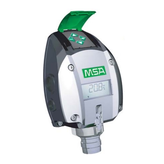
Description Description Identifying the Unit PrimaX P PrimaX I general purpose version, or flameproof version intrinsically safe version Fig. 1 PrimaX Gas Transmitter PrimaX P The PrimaX P is a gas transmitter with an aluminum enclosure. This is a flameproof version for the detection of combustible or toxic gases or oxygen. - Page 10 Description Fig. 2 Exploded View (PrimaX P) Terminal for power connection Sensor Keypad with cover Red LED (PrimaX P only) Connector for factory use Yellow LED (PrimaX P only) Display Green LED (PrimaX P only) Bayonet joint with interlock Identification plate PrimaX...
- Page 11 Description Sensors Description PrimaX P PrimaX I Detection of toxic gases Detection of oxygen Detection of combustible gases The device operates with a 4 – 20 mA output signal. As an optional feature additional modules are available for these configurations of PrimaX transmitter: Modules PrimaX P PrimaX I...
-
Page 12: Installation
Installation Installation The device should be installed where gas leaks are expected. The installation position depends on the gas density, either in the upper area of the room under the ceiling for gases lighter than air or close to the ground for gases heavier than air. Also consider how air movement may affect the ability of the device to detect gas. - Page 13 Installation Wall or Pipe Mounting For pipe mounting a pipe mounting kit is necessary (→ chapter 8.6 "Pipe Mounting Kit"). Install the Backplate Use the two keyhole slots for attaching the mounting plate to the wall. Use 6mm diameter screws and suitable plugs.
-
Page 14: Electrical Installation
Installation Electrical Installation Instructions for Electrical Connection WARNING! The device must be installed only in compliance with the applicable regulations, otherwise the safe operation of the instrument is not guaranteed. • Shielded cable for measuring devices is recommended. • Always observe maximum cable lengths and cross-sections (→ chapter 6.2 "Cable Lengths and Cross-sections"). -
Page 15: Electrical Connection - Primax I
Installation PrimaX P Power supply (+) 24 V DC 0 V DC (-) 4 – 20 mA (Signal) Isolated ground Fig. 5 3-wire/4-wire connection - PrimaX P Unscrew the interlock between cover and bayonet joint of sensor. Unscrew the aluminum lid of the enclosure. Unplug the 4-way terminal block. - Page 16 Installation PrimaX I Power supply (+) 4 – 20 mA (Signal) Fig. 7 2-wire connection - PrimaX I Remove plastic cover. It is bolted with 4 screws. Remove the 2-way terminal block. It is located behind a plastic cover above the display. Unscrew clamping nut at the cable gland.
-
Page 17: Operation
Operation Operation The device is factory-calibrated and delivered ready for installation. Each device is configured and calibrated for only one specific gas or vapor. Fig. 8 Display overview Measuring value/Menu//Text dimensions Calibration Units Alive signal (flashing) LOC, alarm indication (optional) Maintenance Signal for an active communication PrimaX... -
Page 18: Startup
Operation Startup During startup a self-test is performed and the output signal is set to the service current (default 3.0 mA). The following information is displayed: Display Test The display shows all segments. Note: The PrimaX P also shows all LEDs and afterwards the yellow LED is flashing during the startup procedure. -
Page 19: Calibration
Operation The following table lists the menu items. Detailed descriptions can be found in the chapters 4.3 "Cali- bration", 4.4 "Maintenance and Info" and 4.5 "Password". Menu item Text Password? Calibration M-01 ZERO Calibration M-02 Show Test Gas Concentration M-03 Setup Calibration M-04 Sensor Exchange... - Page 20 Operation When monitoring flammable gas in safety related applications the PrimaX must be cali- brated with a known concentration of the gas being monitored. The lower explosive limits (LEL) of the gases and vapors in the following example were taken from EN 60079-20-1.
-
Page 21: Maintenance And Info
Operation Calibration Steps The calibration procedure can be canceled at any time by pressing ESC. The previous transmitter calibration will be used. (M-01) - ZERO and SPAN Gas Calibration Press ENTER and select menu 1. Press ENTER button. Enter password (→ chapter 4.5 "Password"). Apply zero gas (synthetic air). - Page 22 Operation Set the test gas concentration with the UP or DOWN button. Press ENTER button. Set the zero calibration countdown time in seconds with the UP or DOWN button. Note: time = 0 → (manual) zero calibration, otherwise an (automatic) calibration is performed by the device.
- Page 23 Operation (M-07) - Loop Test In this menu a 4 - 20 mA loop test will be performed. Press ENTER and select menu 7. Press ENTER button. Enter password (→ chapter 4.5 "Password"). The loop test mA value is displayed (default value = 12 mA). Press UP or DOWN to change the value.
-
Page 24: Password
Operation (M-10) - Range Selection WARNING! Test gas concentration has to be checked and device has to be calibrated if the range is changed. This menu allows to set up the optional measuring ranges for connected OX/TOX sensors. Press ENTER and select menu 10. Press ENTER button. -
Page 25: Changeable Parameters
Operation Changeable Parameters Values default minimum maximum regarding sensor (e.g.: CO = 60ppm, H S 10ppm, Span/Test Gas Value 10% of Range 100% of Range = 20.8 vol%, combus- tible = 50% LEL) Zero Calibration Time 30 s 2000 s Span Calibration 30 s 2000 s... -
Page 26: Electrical Installation
Operation Electrical installation Fig. 10 HART ports Optional HART port For wiring diagrams → chapter 10.6 "Wiring Diagrams". Relays Relay nominal switching capacity (resistive load): Alarm Relay 2A / 30V DC Failure Relay 2A / 30V DC Fig. 11 Location of Relay Relay Terminals PrimaX... -
Page 27: Relay Operation
Operation ALARM FAILURE Fig. 12 Relay Terminals Alarm Relay Failure Relay Normally closed energised(NC) Normally closed energised(NC) Common (COM) Common (COM) Normally open energised(NO) Normally open energised(NO) Relay Operation Startup If relays are used the alarm threshold will be displayed at startup Menu Sequence Menu item Text... - Page 28 Operation (M-12) - Relay Setup Press ENTER and select menu 12. Press ENTER button. Enter password (→ chapter 4.5 "Password"). Set the alarm threshold with the UP or DOWN button. Press ENTER button. Set rising or falling alarm option with the UP or DOWN button. Press ENTER button.
- Page 29 Operation Changeable Parameters for Relays Values default minimum maximum 30% of Range Alarm threshold 5 % of Range 100% of Range = 20 vol%) Alarm relay normally energized yes Latch alarm decrease; Alarming direction Increasing Decreasing other increase Alarm delay time 600 s Failure relay normally ener- gized...
- Page 30 Operation Output States State Failure Relay Alarm Relay Normal Startup state Startup (default: switched) Calibration Latched voltage overrange Switched Loop not connected Switched Underrange Switched Error Switched Safety critical error Switched LOC (combustible) Switched Latched LOC (combustible) Switched Alarm threshold exceed Switched Switched: the relay state has switched from the normal state.
-
Page 31: Maintenance
Maintenance Maintenance Changing the Sensors DANGER! Remove and reinstall sensors carefully, ensuring that the components are not damaged; otherwise the approval may be adversely affected, wrong readings could occur, and persons relying on this product for their safety could sustain serious personal injury or death. Before changing the sensor, the Sensor Exchange mode must be activated. - Page 32 Maintenance Replace Sensor Unplug the sensor carefully. Plug in the new sensor carefully. Replace the bayonet ring. Replace the interlock. PrimaX...
-
Page 33: Technical Data
Technical Data Technical Data Specifications PrimaX P PrimaX I aluminum enclosure plastic enclosure Enclosure flameproof intrinsically safe IP 67 ingress protection IP 66 ingress protection Dimensions in mm 220 X 162 X 100 220 X 162 X 81 (Height X Width X Depth) Weight 1.6 kg 1.2 kg... -
Page 34: Cable Lengths And Cross-Sections
Technical Data Refresh Rate of Output Signals 4 - 20 mA output signal (analog) 100 ms Alarm (LED and relay) 100 ms Failure (LED and relay) 100 ms Display (measuring value) Display (alarm) 2100 ms Cable Lengths and Cross-sections The maximum load resistance for all combinations is 300 Ohm. Cross- Sensor type Max. -
Page 35: List Of Detectable Gases
Technical Data List of Detectable Gases Default range Selectable range(s) Temperature Range Ammonia (NH 100 ppm 50 ppm -20 – 40 °C Ammonia (NH 500 ppm 1000 ppm -20 – 40 °C 100 ppm Carbon Monoxide (CO) 200 ppm 500 ppm -20 –... - Page 36 Technical Data Resolution of display Measuring range Resolution 1 to 10 25 Vol % oxygen 10 to 2000 Response time (diffusion mode) Oxygen Response time Recovery time ≤8 s ≤ 25 s ≤ 25 s Toxic Response time Recovery time ≤20 s ≤...
-
Page 37: Sensor Response To Interferants
Technical Data Sensor Response to Interferants Interference factors may differ from sensor to sensor and with life time. It is not advisable to calibrate with interference gases. This table does not claim to be complete. The sensor might also be sensitive to other gases. -
Page 38: Primax P List Of Combustible Gases And Vapours Detectable With Catalytic Sensor Part No. 10112716
Technical Data Gas Sensor Interferant 50 ppm NO 20 ppm SO 10 ppm Cl <-5 ppm <-15 ppm <80 ppm 400 ppm H 20 ppm H 400 ppm CO <0.1 ppm <-35 ppm <0.1 ppm Nitrogen Dioxide (NO 20 ppm NH 50 ppm C 5 vol% CO <... - Page 39 Technical Data Response Response time Gas/ Response CAS-No. (vol%) time (s) (t50) (s) (t90) Fluid factor Acetaldehyde (C 75-07-0 fluid 0.64 Acetic acid (C 64-19-7 fluid 1.51 Acetic anhydride 108-24-7 fluid 1.56 ((CH Acetone (C 67-64-1 ≤ 9 ≤ 24 fluid 0.94 Acetylene (C...
- Page 40 Response times are with a flow through adapter and a gas flow of 1 l/min Response factor defined by DEKRA EXAM Response factor defined by MSA (not included in the EC-Type Examination Certificate BVS 10 ATEX E 009 X) PrimaX...
-
Page 41: Approvals
Approvals Approvals Marking, Certificates and Approvals according to the Directive 2014/34/EU (ATEX) and National Standards PrimaX P MSA Europe GmbH Manufacturer: Schlüsselstr.12 CH - 8645 Rapperswil-Jona Product: PrimaX P EC-Type Examina- BVS 10 ATEX E009 X tion Certificate: EN 60079-0:2012 + A11:2013, EN 60079-1:2014,... - Page 42 Approvals HART Module Connector, only for temporary connection of an intrinsic safe HART Field Option: Communicator ≤ 200 mW, U ≤ 2,7 V, I ≤ 137 mA, L ≤ 10 µH, C ≤ 1 nF ≤ 5 mW, U ≤ 5 V, I ≤...
- Page 43 Approvals PrimaX I MSA Europe GmbH Manufacturer: Schlüsselstrasse 12 CH-8645 Rapperswil-Jona Product: PrimaX I EC-Type Examination Certificate: BVS 10 ATEX E009 X Standards: EN 60079-0:2012 + A11:2013, EN 60079-11:2012 Performance EN 50104 :2010, EN 50271 :2010 Gas: Oxygen: 0-10 % (V/V), 0-25 % (V/V) PFG 11 G 001: EN 45544 -1:1999;...
-
Page 44: Marking And Certificates According To Iecex
Approvals Marking and Certificates according to IECEx PrimaX P MSA Europe GmbH Manufacturer: Schlüsselstrasse 12 CH-8645 Rapperswil-Jona Product: PrimaX P IEC-Type Examination Certificate: IECEx BVS 10.0043 X IEC 60079-0:2011, IEC 60079-1:2014, Standards: IEC 60079-11:2011 IEC 60079-31:2013 Perfomance: none Gas: see manual... - Page 45 Approvals Special conditions for safe use: • Do not open the instrument when energized. • For dust applications the installation conditions according to EN 60079-31 have to be considered. • Intensive electrostatic charging processes on the instrument label have to be prevented on the instrument label.
- Page 46 Approvals PrimaX I MSA Europe GmbH Manufacturer: Schlüsselstrasse 12 CH-8645 Rapperswil-Jona Product: PrimaX I IEC-Type Examination Certificate: IECEx BVS 10. 0043 X Standards: IEC 60079-0:2011, IEC 60079-11:2011 Performance: Gas: see manual Marking: Prima X I Ex ia IIC T4 Ga -40°C≤...
-
Page 47: Special Conditions For The Safe Use According To Atex And Sil
Approvals Special conditions for the safe use according to ATEX and SIL applications Safety relevant parameters for the Gas Transmitters Type Structure 1oo1 or 1oo2 0 or 1 PFD, PFH, SFF see table , λ , λ , λ see table λ... - Page 48 Approvals General conditions for the safe use • The application advice and the limitations of the manual have to be considered. For calibration and maintenance, the regional and national regulations have to be considered. • A defect transmitter has to be repaired within 72 hours. ®...
- Page 49 Approvals Special conditions for SIL 2 • The use of the sensors in a High Demand or Continuous Mode is allowed only in a 1002 - struc- ture. • The outputs of the sensors (4-20 mA - loops and relay contacts) must to be monitored regarding deviations.
-
Page 50: Safety Relevant Parameters (40°C)
Safety Relevant Parameters Safety Relevant Parameters [40°C]t Application with Relay λ λ λ λ λ total 1oo1 1oo1 1oo2 1oo2 1oo2 1oo2 1oo2 1oo2 % of SIL % of SIL 3 1/h % of SIL 1 1/h % of SIL 3 Ammonia (NH 3737 2469... -
Page 51: Application With 4-20 Ma Current Output
Safety Relevant Parameters Application with 4-20 mA Current Output λ λ λ λ λ total 1oo1 1oo2 1oo2 1oo2 1oo2 1oo2 1oo2 % of SIL 2 % of SIL 3 1/h % of SIL 1 1/h % of SIL 3 Ammonia 1734 79.1... -
Page 52: Accessories
Accessories Accessories For part numbers → chapter 9 "Spare Parts". Calibration Cap Using calibration cap allows span gas calibration procedure to be accurate in windy environmental conditions. The calibration cap is pushed on to the front of the sensor and is sealed by an O- ring. The surface area S <... -
Page 53: Remote Calibration
Accessories Remote Calibration Fig. 15 PrimaX with CalGard The CalGard stainless steel remote calibration adaptor provides reliable operation of remotely installed gas detectors working under harsh environmental conditions. Additionally, the CalGard allows remote verification ("bump test") or instrument calibration of gases listed later in this section and oxygen via a hose connection in the presence of wind speeds up to 6 m/s. -
Page 54: Operation
, CH , CO and H S in air, O in N Applicable test gases (approval of other gases by MSA on request) Recommended flow rate 1.0 l / min Minimum flow rate 0,8 l / min Maximum flow rate 1.5 l / min... -
Page 55: Flow Through Adapter
Accessories Flow Through Adapter Fig. 16 Flow through adapter The flow through adapter is for use with a pumped sampling system. Gas inlet/outlet thread: 1/8” NPT Gas flow rate: 1.0 l/min Using the flow through adapter will extend the response time, depending on the gas flow rate. -
Page 56: Pipe Mounting Kit
Accessories The performance of the duct mounting kit depends on various parameters and has to be checked before usage. The kit was not part of the compliance test. Pipe Mounting Kit The PrimaX can be mounted vertically by fastening its back plane using two screws and washers. Additionally, a pipe mount kit allowing the PrimaX to be fixed to pipes or poles is available as an acces- sory. -
Page 57: Sensor Tag
Accessories Sensor Tag Fig. 21 Sensor tag Fig. 22 Measurements sensor tag The stainless steel label allows to identify and tag the location or installation of the instrument on the site. PrimaX... -
Page 58: Sunshield
Accessories Sunshield Fig. 23 Sunshield Stainless steel plate to protect the transmitter from direct sunlight. Universal HART Cable Fig. 24 Universal HART cable Universal cable that will connect the PrimaX detector to any standard HART handheld (f.e. Emerson 375) using the HART connector. PrimaX... -
Page 59: Spare Parts
Spare Parts Spare Parts List of Accessories Description Material Part No. Sensor Gard Plastic 10113033 Flow Through Adapter St.St. 316 10113031 Duct Mounting Kit St.St. 316 10112790 Pipe Mounting Kit St.St. 316 10113032 Sensor Tag St.St. 316 10113034 Sunshield St.St. 316 10113035 Calibration Cap Plastic... - Page 60 Spare Parts Range (optional) Part No. 200 ppm (100 ppm, 500 ppm, Carbon Monoxide (CO) 711306 1000 ppm) Chlorine (CL 10 ppm (5 ppm) 10112720 Hydrogen (H 1000 ppm 10112723 Hydrogen Chloride (HCl) 30 ppm (10 ppm, 20 ppm) 10112721 30 ppm (10 ppm, 20 ppm, 50 Hydrogen Cyanide (HCN) 10080220...
-
Page 61: Appendix
Appendix Appendix 10.1 Output States Display Alternating LED colour State Signal current Default Green Normal 4 – 20 mA Yellow (flashing) Startup Service current 3 mA Yellow (flashing) Calibration Service current 3 mA Yellow Calibration invalid Service current 3 mA Latched voltage overrange VCC ... -
Page 62: Calibration Errors
The removal of the hydrogen cyanide and chlorine sensors will not trigger the E-28 sensor error message. For additional support please contact MSA Service. Sensor errors (E-20 – E-29) could be cleared by checking if the sensor is well connected, or by changing the sensor, or also by resetting the device. -
Page 63: Mechanical Installation
Appendix 10.5 Mechanical Installation Dimensions Fig. 25 Outline dimensions Prima X P Fig. 26 Outline dimensions Prima X I Cable gland • M25 x 1,5;Torque 8 -12 Nm; only ATEX certified versions for gas and dust shall be used. • NPT ¾"- 14;... - Page 64 Appendix Fig. 27 Installation mounting plate Fig. 28 Dimensions sunshield PrimaX...
- Page 65 Appendix Fig. 29 Duct mounting Fig. 30 Dimensions CalGard PrimaX...
-
Page 66: Wiring Diagrams
Appendix 10.6 Wiring Diagrams The HART communications require a minimum of 250 ohms resistance in the 4 – 20 mA loop. PrimaX I, Ex ia, Intrinsically Safe Controller + 24V Suprema GasGard XL 4 - 20mA 9010/20 max = 70 Ω max = 300 Ω... - Page 67 Appendix PrimaX P, Ex d, Flameproof Ex d max = 35 Ω + 24V 1 , 24V DC Cable 2 , 0 V DC Suprema 3 , 4 – 20 mA 4 - 20 mA GasGard XL 4 - 20mA 9010/20 max = 300 Ω...
- Page 68 Appendix RELAYS OPTION Ex d ALARM FAILURE + 24V 1 , 24V DC max = 25 Ω Cable 2 , 0 V DC Suprema 3 , 4 – 20 mA 4 - 20 mA GasGard XL 4 - 20mA 9010/20 max = 300 Ω...
- Page 69 Appendix Ex d [ ia ] + 24V 1 , 24V DC max = 20 Ω Cable 2 , 0 V DC 3 , 4 – 20 mA 4 - 20 mA 4 , GND 4 - 20mA max = 20 Ω / 200 Ω Cable HART Port [ ia ] max = 300 Ω...
- Page 70 For local MSA contacts, please visit us at MSAsafety.com Because every life has a purpose...
- Page 71 Thank you for reading this data sheet. For pricing or for further information, please contact us at our UK Of ce, using the details below. Please note — Product designs and speci cations are subject to change without notice. The user is responsible for determining the suitability of this product.
Need help?
Do you have a question about the PrimaX Series and is the answer not in the manual?
Questions and answers