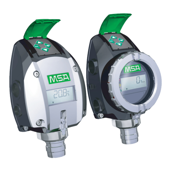
MSA PrimaX Operating Manual
Gas transmitter
Hide thumbs
Also See for PrimaX:
- Operating manual (74 pages) ,
- Instruction manual (64 pages) ,
- Quick start manual (3 pages)
Table of Contents
Advertisement
Advertisement
Table of Contents

Related Manuals for MSA PrimaX


Summary of Contents for MSA PrimaX
- Page 1 Operating Manual PrimaX Gas Transmitter Order No. 10115083/00...
- Page 2 MSA AUER GmbH Thiemannstrasse 1 D-12059 Berlin Germany © MSA AUER GmbH. All rights reserved...
-
Page 3: Declaration Of Conformity
Thiemannstraße 1 D-12059 Berlin declares that the product PrimaX I, PrimaX P based on the EC-Type Examination Certificate: BVS 10 ATEX E009 X complies with the ATEX directive 94/9/EC, Annex III. Quality Assurance Notification complying with Annex IV of the ATEX Directive 94/9/EC has been issued by DEKRA EXAM in Bochum, Notified Body number: 0158. -
Page 4: Table Of Contents
Safety Regulations ....................6 Correct Use ....................6 Liability Information ..................6 Safety and Precautionary Measures to be Adopted ........7 MSA Permanent Instrument Warranty ............8 Description ......................9 Identifying the Unit ..................9 Overview ....................... 9 Installation ......................11 Mechanical Installation ................ - Page 5 Universal HART Cable ................47 Spare Parts ......................47 Appendix ....................... 50 11.1 Output States ....................50 11.2 Calibration Faults ..................51 11.3 Error Codes ....................51 11.4 Timeout ....................... 52 11.5 Mechanical Installation ................52 11.6 Wiring Diagrams ..................53 PrimaX...
-
Page 6: Safety Regulations
The signal of the transmitter can be used in combination with MSA control units for further actions in safety or non safety applications, e. g. MSA SUPREMA, Gasgard XL, 9010/9020. -
Page 7: Safety And Precautionary Measures To Be Adopted
Such paint deposits would interfere with the gas diffusion process. Use only genuine MSA replacement parts when performing any maintenance procedures provided in this manual. Failure to do so may seriously impair instru- ment performance. -
Page 8: Msa Permanent Instrument Warranty
Safety Regulations maintenance instructions or by anyone other than an authorised MSA service personnel, could cause the product to fail to perform as designed. The device is designed for applications in hazardous areas under atmospheric conditions. For correct measurements, the combustible gas sensors require an oxygen concentration greater than 10 Vol%. -
Page 9: Description
PrimaX I The PrimaX I is a gas transmitter with a plastic enclosure. It is available as a general purpose version [not intended for hazardous area] or intrinsically safe version. Both versions are designed for a detection of toxic gases or oxygen. - Page 10 The device operate with a 4 – 20 mA output signal and an IP 66 ingress protection. Fig. 2 Exploded View [PrimaX P] Terminal for power connection Sensor Keypad with cover red LED [PrimaX P only] Connector for factory use yellow LED [PrimaX P only] Display green LED [PrimaX P only] bayonet joint with interlock...
-
Page 11: Installation
Installation Sensors Description PrimaX P PrimaX I Detection of toxic gases Detection of oxygen Detection of combustible gases The device operates with a 4 – 20 mA output signal and an IP 66 ingress protection. As an optional feature additional modules are available for these configurations of... -
Page 12: Mechanical Installation
Installation Mechanical Installation Preparation To install the device, first remove the backplate. Undo Screws (1) Unscrew the device. Remove Device (2) Remove the device from the backplate by lifting up the lower edge as shown. PrimaX... - Page 13 Attach the Device to the Backplate Attach the device to the top of the back- plate. (5) Fold down the device, till it is closed to the backplate. Fasten Device (6) Screw the device to the backplate. PrimaX...
-
Page 14: Electrical Installation
The power supply is defined as 24 VDC. If the input supply voltage at the terminal of the transmitter is less than 10 V, the device will shut down. Operating the PrimaX I version in hazardous areas requires an intrinsically safe power supply. Electrical Connection - PrimaX P... - Page 15 4 – 20 mA [Signal] 0 V DC [-] isolated ground Fig. 5 3-wire connection - PrimaX P (1) Unscrew the interlock between cover and bayonet joint of sensor. (2) Unscrew the aluminium lid of the enclosure. (3) Unplug the 4-way terminal block.
- Page 16 Installation Electrical Connection - PrimaX I Terminal PrimaX I Fig. 6 Terminal PrimaX I Power supply [+], 24 V DC 4 – 20 mA [Signal] PrimaX I Power supply [+] 4 – 20 mA [Signal] Fig. 7 2-wire connection - PrimaX I (1) Remove plastic cover.
-
Page 17: Operation
The device is factory-calibrated and delivered ready for installation. Each device is configured and calibrated for only one specific gas or va- pour. Fig. 8 Display overview Measuring value/Menu//Text dimensions Calibration Units Alive signal [flashing] LOC, alarm indication [optional] Maintenance Signal for an active communication PrimaX... -
Page 18: Startup
[default 3.0 mA]. The following information is displayed: Display Test The display shows all segments. Note: The PrimaX P also shows all LEDs and afterwards the yellow LED is flash- ing during the startup procedure. Software Version The display shows the firmware version. -
Page 19: Menu Sequence
(3) Press ENTER button to get access to the menu, (4) Press ESC button to cancel the process. The following table lists the menu items. Detailled descriptions can be found in the chapters 4.3, 4.4 and 4.5. PrimaX... -
Page 20: Calibrations
It is recommended that all calibration components are connected before starting a calibration as it is necessary to apply test gas to the device during a countdown. The calibration can be performed as a manual or an automatic calibra- tion [→ M-04]. PrimaX... - Page 21 (1) Press ENTER and select menu 1. (2) Press ENTER button. (3) Enter password [→ chapter 4.5]. (4) Apply synthetic air. (5) Wait until countdown is finished [automatic] or press ENTER [manual]. OK is displayed. (6) The device goes to measuring mode. PrimaX...
-
Page 22: Maintenance And Info
(7) Press ENTER button. (8) Set the span calibration countdown in seconds with the UP or DOWN button. Note: time = 0 → [manual] span calibration, otherwise an [automatic] cali- bration is carried out by the device. (9) Press ENTER button. PrimaX... - Page 23 (7) [Perform a ZERO and SPAN or Oxygen calibration [M-01]. [M-06] - LCD/LED Test LCD and LED test [LED only available in PrimaX P]. All segments will be displayed and the LEDs will flash sequentially. (1) Press ENTER and select menu 6.
- Page 24 If an OX/TOX sensor is connected this menu shows the measured mV value. If a COMB sensor is connected this menu shows the detector [U ], compensator ] and differential voltage [U ] in mV. Go through the information with the ENTER button. PrimaX...
- Page 25 LOC of combustible sensor or an alarm. It appears only in the menu if there is a latched LOC or alarm. (1) Press ENTER and select menu 0. (2) Press ENTER button. (3) Enter password [→ chapter 4.5]. Success message confirms that latched alarm is reset. PrimaX...
-
Page 26: Password
Span Calibration 30 s 0 seconds 2000 s Time Idle Time after 30 s 2000 s calibration Range See 6.4 List of detectable gases Loop Test 12 mA 2 mA with 22 mA 2-wire version 0 mA with 3/4-wire version PrimaX... -
Page 27: Optional Hart Module And Relay
ZERO SPAN Calibration / Oxygen Calibration; ZERO Calibration; Sen- sor Exchange; LCD/LED Test; Loop Test; Range setup; Reset alarm; Readout all measured data and information. Electrical Installation Fig. 10 HART ports Optional HART port For wiring diagrams → chapter 10.6. PrimaX... - Page 28 Operation Relays Fig. 11 Location of Relay Relay Terminals ALARM FAILURE Fig. 12 Relay Terminals Alarm Relay Failure Relay Normally closed energised[NC] Normally closed energised[NC] Common [COM] Common [COM] Normally open energised[NO] Normally open energised[NO] PrimaX...
- Page 29 The alarm threshold and if the alarm is activated with a rising or falling gas con- centration. if an alarm would be latched. the alarm relay delay time in seconds. if the alarm relay is energised at alarm. the failure relay delay time in seconds. if the failure relay is energised at failure. PrimaX...
- Page 30 (1) Press ENTER and select menu 13. (2) Press ENTER button. (3) Enter password [→ chapter 4.5]. (4) The relays are now Switched and can be tested. (5) Press ENTER button to go back to menu or ESC to go back to measuring mode. PrimaX...
- Page 31 For all parameters which can be changed over keypad see chapter 4.6. For relay parameters which can be changed over keypad see above. Values default minimum maximum Password 0000 0000 9999 Description PrimaX Long tag Message Enable LOC if combustible enable enable disable PrimaX...
- Page 32 Normally de-en- ergised if alarm/failure meets the ATEX and SIL requirements. LOC: The PrimaX Gas Monitor has been exposed to a high gas concentration [above the LEL], and there is a possibility that the over-range condition may still ex- ist.
-
Page 33: Maintenance
If changing the sensor, reset the sensor life time counter. To reset the counter → chapter 4.2 M-05. PrimaX... - Page 34 (3) Turn the bayonet ring counter-clock- wise. (4) Remove the bayonet ring by pulling it down. Replace Sensor (5) Unplug the sensor carefully. (6) Plug in the new sensor carefully. (7) Replace the bayonet ring. (8) Replace the interlock. PrimaX...
-
Page 35: Technical Data
Technical Data Technical Data Specifications PrimaX P PrimaX I aluminium enclosure plastic enclosure Enclosure flameproof intrinsically safe IP 66 ingress protection IP 66 ingress protection Dimensions in mm 220 X 162 X 100 220 X 162 X 81 [Height X Width X Depth] Weight 1.6 kg... -
Page 36: Cable Lengths And Cross-Sections
610 m 457 m Cross-section 1.5 mm 1067 m 762 m Max. load resistance at signal output 300 Ohm Version Wire Min. supply voltage 2-wire 1 mm 19.2 % 3-wire 1.5 mm 19.2 % 4-wire 1.5 mm 19.2 % PrimaX... -
Page 37: Performance Specifications
10 ppm -20 – 40 °C 20 ppm Hydrogen Fluoride [HF] 10 ppm 5 ppm -20 – 40 °C Hydrogen [H 1000 ppm -20 – 50 °C Nitrogen Dioxide [NO 10 ppm 20 ppm -20 – 50 °C 100 ppm PrimaX... - Page 38 Hydrogen Bromide [HBr] 30 ppm -20 – 40 °C Germane [GeH 2 ppm -20 – 40 °C Fluorine [F 1 ppm -10 – 40 °C Diborane [B 1 ppm Bromine [Br 10 ppm Arsine [AsH 1 ppm -20 – 40 °C PrimaX...
-
Page 39: Sensor Response To Interferants
10 ppm NO 0.25 ppm O 20 ppm SO 2 ppm 0.05 ppm 3.5 ppm Sulphur Dioxide [SO 300 ppm CO 5 ppm NO <3 ppm -5 ppm Hydrogen Cyanide [HCN] 100 ppm NO 10 ppm NO -5 ppm -7 ppm PrimaX... - Page 40 Silane [SiH 0.2 ppm AsH 0.25 ppm B 20 ppm HCN 0.2 ppm 0.12 ppm 0.5 ppm 2 ppm H 0.1 ppm PH 20 ppm SO 8 ppm 0.13 ppm 4 ppm 10 ppm NO -2 ppm Germane [GeH PrimaX...
- Page 41 1 ppm Cl 1 ppm 1 ppm 1.4 ppm 0.25 ppm B 1 ppm HCN 1 ppm H 0.4 ppm -3 ppm -2 ppm 10 ppm NO 0.25 ppm O 20 ppm SO -19 ppm 0.3 ppm 0.04 ppm PrimaX...
-
Page 42: Approvals
Approvals Approvals Marking, Certificates and Approvals According to the Directive 94/9/EC [ATEX] PrimaX P Manufacturer: MSA AUER GmbH Thiemannstraße 1 D-12059 Berlin Product: PrimaX P Type of protection: EN 60079-0:2009, EN 60079-1:2007, EN 60079-11:2007, IEC 60079-31:20086 Measuring function for explosion... - Page 43 Approvals PrimaX I Manufacturer: MSA AUER GmbH Thiemannstraße 1 D-12059 Berlin Product: PrimaX I Type of protection: EN 60079-0:2006, EN 60079-11:2007, EN 60079-26:2007, EN 61241-11:2006 Measuring function for explosion protection: Gas: see manual Marking: Prima X I II 1G Ex ia IIC T4 Ga II 2D Ex ia IIIC T130°C Db...
-
Page 44: Marking And Certificates According To Iecex
Approvals Marking and Certificates according to IECEx PrimaX P Manufacturer: MSA AUER GmbH Thiemannstraße 1 D-12059 Berlin Product: PrimaX P Type of protection: IEC 60079-0:2007, IEC 60079-1:2007, IEC 60079-11:2006, IEC 60079-31:2009 Measuring function for explosion protection: Gas: see manual Marking:... - Page 45 Approvals PrimaX I Manufacturer: MSA AUER GmbH Thiemannstraße 1 D-12059 Berlin Product: PrimaX I Type of protection: IEC 60079-0:2007, IEC 60079-11:2006, IEC 60079-26:2006, IEC 61241-11:2005 Measuring function for explosion protection: Gas: see manual Marking: Prima X I Ex ia IIC T4 Ga Ex ia IIIC T130°C Db...
-
Page 46: Accessories
The calibration port must be sealed again with the locking cap after calibration has been carried out. Calibration should only be carried out with the calibration port if the air velocity is < 5 m/s in the air duct. PrimaX... -
Page 47: Pipe Mounting Kit
Sunshield Stainless steel plate to protect the transmitter from direct sunlight. Universal HART Cable Universal cable that will connect the PrimaX detector to any standard HART hand- held [f.e. Emerson 375] using the HART connector. Spare Parts List of Accessories... - Page 48 Spare Parts Description Part No Keyboard cover 10113040 Cable gland M25 x 1.5, 7 – 17 mm 10113039 PrimaX P Replacement Parts Description Part No Bayonet lock plate & screw 10113050 Sensor bayonet and cap 10113058 Mounting plate 10113041 10113056...
- Page 49 Arsine [AsH 1 ppm available on request Electrochemical sensors should only ordered for immediate replace- ment.The storage temperature should be in the range of +5° C to +12° C. Disposal of electrochemical sensors has to be carried out pro- fessionally PrimaX...
-
Page 50: Appendix
LOC [if combustible] 20.5 mA [flashing] Latched LOC 20.5 mA [if combustible] LOC: The PrimaX Gas Monitor has been exposed to a high gas concentration [above the LEL], and there is a possibility that the over-range condition may still ex- ist. PrimaX... -
Page 51: Calibration Faults
For latched errors E-01 to E-29 pressing any key initiates a reset. Sensor errors [E-20 – E-29] could be cleared by checking if the sensor is well con- nected, or by changing the sensor, or also by resetting the device. PrimaX... -
Page 52: Timeout
60 minutes [M-01, M-02]. Any test procedure [M-06, M-07] has a timeout of 15 minutes. Anywhere else in the menu the timeout is 2 minutes, if no button is pressed. 10.5 Mechanical Installation Dimensions Fig. 13 Outline dimensions Prima X P Fig. 14 Outline dimensions Prima X I PrimaX... -
Page 53: Wiring Diagrams
Appendix 10.6 Wiring Diagrams The HART communications require a minimum of 250 ohms resistance in the 4 – 20 mA loop. PrimaX I, Ex ia, Intrinsically Safe Controller + 24V Suprema GasGard XL 4 - 20mA 9010/20 max = 70 Ω... - Page 54 Cable 24V DC +24V Controller + 12 Suprema - 10 4-20mA GasGard XL STAHL 9010/20 9160/13-11-11 max = 220 Ω Cable +24V Controller + 12 Suprema - 10 GasGard XL 4-20mA STAHL 9010/20 9160/13-10-11 max = 220 Ω Cable PrimaX...
- Page 55 Appendix PrimaX P, Ex d, Flameproof Ex d max = 35 Ω + 24V 1 , 24V DC Cable 2 , 0 V DC Suprema 3 , 4 – 20 mA 4 - 20 mA GasGard XL 4 - 20mA 9010/20 max = 300 Ω...
- Page 56 Cable 2 , 0 V DC Suprema GasGard XL 3 , 4 – 20 mA 4 - 20 mA 9010/20 4 , GND 4 - 20mA max = 20 Ω / 200 Ω Cable max = 300 Ω Load PrimaX...
- Page 57 2 , 0 V DC Cable Suprema GasGard XL 3 , 4 – 20 mA 4 - 20 mA 9010/20 4 , GND 4 - 20mA max = 15 Ω / 200 Ω Cable max = 300 Ω Load PrimaX...
- Page 58 MSA in Europe www.msa-europe.com & www.msa-gasdetection.com Northern Europe Southern Europe Eastern Europe Central Europe Netherlands France Poland Germany MSA Nederland MSA GALLET MSA Safety Poland MSA AUER Kernweg 20 Zone Industrielle Sud ul. Wschodnia 5A Thiemannstrasse 1 1627 LH Hoorn 01400 Châtillon sur...
Need help?
Do you have a question about the PrimaX and is the answer not in the manual?
Questions and answers