Table of Contents
Advertisement
Available languages
Available languages
Quick Links
NOT1803
06.2022
Sanifos®
Sanifos® 110
Sanifos® 280
Sanifos® 610
Sanifos® 1300
Station de relevage à enterrer ou à poser
FR •
Notice d'installation et de service
Pumping station for waste water, floor-standing or underground
EN •
Installation and operating manual
Abwasserhebeanlage für den Erdeinbau oder die Aufstellung
DE •
Bedienungs-/Installationsanleitung
Stazione di sollevamento per acque reflue da interrare o posare
IT •
Manuale per l'uso e l'installazione
Pompinstallatie voor afvalwater, voor ingraving of plaatsing
NL •
Installatie- en gebruikshandleiding
Estación elevadora de aguas residuales para enterrar o instalar
ES •
Manual de instalación e uso
Estação elevatória para águas residuais para enterrar o montar
PT •
Instruções de instalação e funcionamento
Stație de pompare a apelor reziduale îngropată sau instalată pe sol
RO •
Instrucţiuni de instalare şi utilizare
Szennyvíz szivattyútelep, padló vagy földalatti beépítés
HU •
Beépítési és kezelési kézikönyv
Advertisement
Chapters
Table of Contents

Related Manuals for SFA Sanifos 110


Summary of Contents for SFA Sanifos 110
- Page 1 NOT1803 06.2022 Sanifos® Sanifos® 110 Sanifos® 280 Sanifos® 610 Sanifos® 1300 Station de relevage à enterrer ou à poser FR • Notice d’installation et de service Pumping station for waste water, floor-standing or underground EN • Installation and operating manual Abwasserhebeanlage für den Erdeinbau oder die Aufstellung DE •...
-
Page 2: Table Of Contents
être divulgués, reproduits, modi- fiés ou communiqués à des tiers sauf autorisation écrite du fabricant. Ce document pourra faire l’objet de modifications sans préavis. 10. GARANTIE SFA – 41 Bis Avenue Bosquet – 75007 PARIS... -
Page 3: Sécurité
1. SÉCURITÉ 1.1 IDENTIFICATIONS DES AVERTISSEMENTS Signification DANGER Ce terme définit un danger à risques élevés pouvant conduire à la mort ou à une blessure grave s’il n’est pas évité. AVERTISSEMENT Ce terme définit un danger à risques moyens pouvant conduire à... -
Page 4: Conséquences Et Risques En Cas De Non-Respect De La Notice De Service
étudié la présente notice de service et de montage. Avant d’intervenir sur la station de relevage, la mettre à l’arrêt et couper l’alimentation électrique. • Respecter impérativement la procédure de mise à l’arrêt de la station de relevage décrite dans la présente notice de service. •... -
Page 5: Elimination En Fin De Vie
• Rincer la station de relevage, en particulier lorsqu’elle a véhiculé des liquides nuisibles ou présentant un autre danger. 2.5 ELIMINATION EN FIN DE VIE Ce produit doit être remis en fin de vie à un point de collecte dédié. •... -
Page 6: Conception Et Mode De Fonctionnement
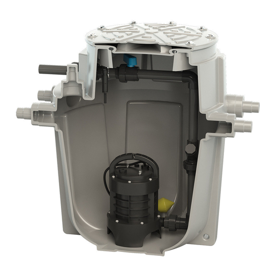
3.4 CONCEPTION ET MODE DE FONCTIONNEMENT Sanifos® 110 La station de relevage possède des entrées pour conduite d'arrivée d'eau ( ) ou des zones de perçage laté- Sanifos® 280 Sanifos® 610 Sanifos® 1300 rales ( L’ensemble moteur-pompe achemine le fluide pompé dans la tuyauterie de refoulement. La conduite de ventilation permet à... -
Page 7: Caractéristiques Techniques
3.5 CARACTÉRISTIQUES TECHNIQUES Sanifos® 110 Sanifos® 280 Sanifos® 610 Sanifos® 1300 Volume de la cuve 110 litres 280 litres 610 litres 1300 litres Matériaux cuve polyéthylène polyéthylène polyéthylène polyéthylène FEA sans réhausse 182 mm 250-600 mm 325-580 mm 560-1460 mm FEA avec réhausse 550-900 mm 725-980 mm... -
Page 8: Réservoir Collecteur
3.6.3 Sanifos® 610 AVEC RÉHAUSSE Ø1080 Ø1000 2 points d’ancrage 3.6.4 Sanifos® 1300 AVEC RÉHAUSSE Ø830 4x Ø100 1000 2 points d’ancrage 3.7 RÉSERVOIR COLLECTEUR Le réservoir collecteur est conçu pour un fonctionnement sans pression. Les eaux usées y sont collectées à la pression atmosphérique avant d’être évacuées vers le collecteur d’égout. -
Page 9: Installation De La Pompe Dans La Cuve
4.2 INSTALLATION DE LA POMPE DANS LA CUVE 4.2.1 SANIFOS® 110 • Connecter la canalisation à la pompe (livrée séparément). • Une fois les raccordements effectués, descendre la pompe submersible et sa tuyauterie à l’intérieur de la cuve puis reconnecter les canalisations. 4.2.2 SANIFOS®... - Page 10 Préparation des borniers 2 PÔLES Version standard à vis Version à perforation de la gaine Outil de fixation rapide Ne pas dénuder 5 PÔLES 5 PÔLES...
-
Page 11: Montage Du Couvercle De La Cuve
Flotteurs Sanifos® 610 et Sanifos® 1300 • Rassembler les câbles flotteurs. • Les fixer à la barre inox à l’aide d’un tyrap. 4.3.2 Sortie des câbles Cas où la station est posée au sol sans presse-étoupes (ex : avec Sanisub ZPK AV) : Passer le câble par la ventilation. -
Page 12: Ventilation
4.5 VENTILATION AVIS Ventilation insuffisante. Risque de non fonctionnement de la station de relevage ! La ventilation doit rester libre. Ne pas boucher la sortie d’évent. Ne pas installer de clapet d’admission d’air (clapet à membrane). Selon les préconisations de la norme EN 12050-1, les stations de relevage doivent être munies d’une ventilation. La station de relevage doit impérativement être ventilée afin que la cuve soit toujours à... -
Page 13: Orifices D'arrivée D'eau
4.7 ORIFICES D’ARRIVÉE D’EAU Sanifos® 110 4 entrées disponibles : • 2 entrées latérales Ø ext. 40/50 • 2 entrées latérales Ø ext. 100/110/125 Sanifos® 280 Sanifos® 610 Sanifos® 1300 1 entrée latérale disponible DN50 ou DN100 1 entrée latérale disponible Ø ext. 160 à... -
Page 14: Installation De La Station De Relevage, Posée
être isolée conformément aux recommandations locales en vigueur. Le risque de gel peut être limité en enterrant plus profondément la station, SFA propose en accessoires des rehausses de 30 cm pour Sanifos® 280, de 40 cm pour Sanifos® 610 et Sanifos® 1300. -
Page 15: Adapter La Hauteur Du Couvercle Au Terrain
5.3 ADAPTER LA HAUTEUR DU COUVERCLE AU TERRAIN Le couvercle antidérapant est vissé. Sanifos® 280 Sanifos® 610 SFA peut fournir en option une réhausse de 300 mm pour les modèles , de 400 mm pour les Sanifos® 1300 AVIS Il est interdit de stationner ou de rouler sur les stations de relevage Sanifos® 280, Sanifos® 610 et Sanifos®... -
Page 16: Raccordement Électrique
5.4 RACCORDEMENT ÉLECTRIQUE DANGER Travaux de raccordement électrique réalisés par un personnel non qualifié. Danger de mort par choc électrique ! Le raccordement électrique doit être réalisé par un électricien qualifié et habilité. L’installation électrique doit correspondre aux normes en vigueur dans le pays. Se référer aux notices d'installation/utilisation de la pompe et du boîtier de commande pour le raccordement électrique. -
Page 17: Utilisation
taire des effluents jusqu'à la cuve (et que le FEA permet bien d'avoir le couvercle de la cuve au niveau du sol). • Contrôler le serrage des colliers des raccords d’arrivée et d’évacuation des eaux usées. Sanifos® 1300 • Contrôler la présence de la ventilation de cuve (diamètre 75, diamètre 100 pour ). -
Page 18: Mise Hors Service
Si cela n’est pas le cas, contacter le service technique SFA au 01 44 82 25 55 pour toute intervention de maintenance sur Sanifos® la station de relevage Liste des points de contrôle lors de la maintenance :... -
Page 19: Contrat De Maintenance
• Contrôler l’état général de la pompe, des câbles électriques, du/des flotteur(s) et du couteau. Contacter le service tech- nique SFA en cas de dysfonctionnement d’un élément. • Nettoyer et contrôler le bon fonctionnement du clapet anti-retour. • Redescendre la pompe dans la cuve. - Page 20 9.2 inspection and maintenance ..........36 reproduced, modified or disclosed to third parties except upon written consent from the manufacturer. 9.3 Maintenance contract ............37 This document may be subject to change without notice. 10. GUARANTEE SFA - 41 Bis Avenue Bosquet - 75007 PARIS...
-
Page 21: Safety
1. SAFETY 1.1 IDENTIFICATION THE WARNING SIGNS Signification DANGER This term defines a high risk of danger, which can lead to death or serious injury, if not avoided. WARNING This term defines a medium-risk hazard that can lead to minor to serious injury if not avoided. -
Page 22: Risks And Consequences Of Non-Compliance With The Operating Manual
• Follow all the safety precautions and instructions in this operating (and installation) manual. This operating manual must always be available on the site so it can be accessed by qualified staff and the operator. These operating instructions must be retained by the operator. 1.6 RISKS AND CONSEQUENCES OF NON-COMPLIANCE WITH THE OPERATING MANUAL Failure to comply with this operating and installation manual will result in the loss of... -
Page 23: Scope Of Supply (See Attached Leaflet)
They can be installed, placed inside the house or buried outside. The tanks of the stations are made from high density polyethylene and have a high mechanical resistance, are odour-resis- tant, UV-resistant and resistant to chemical attack. Their lid is screwed and held in place by a safety screw (not provided). The tanks of the stations are delivered with 1 or 2 pumps depending on the model. -
Page 24: Technical Specifications
3.4.1 Sanifos® 110 , Sanifos® 280 and Sanifos® 610 (single-pump model) Sanifos® 110 Operating mode: VENTILATION Ø ext. 75 Effluents enter the pumping station through the horizon- tal inlet openings. They accumulate in a gas-tight, smell-proof and waterti- ght plastic tank. As soon as a certain fill level is detected by the float swit- INLET Ø... -
Page 25: Product Dimensions
Sanifos® 110 Sanifos® 280 Sanifos® 610 Sanifos® 1300 DN40 Øext 50/ DN40 Øext 50/ DN40 Øext 50/ DN50 Discharge diameter DN50 Øext 63 DN50 Øext 63 DN50 Øext 63 Øext 50 depending on the model depending on the model depending on the model 2 x Ø... -
Page 26: Sump Tank
Sanifos® 1300 WITH EXTENSION Ø830 4x Ø100 1000 2 anchor points 3.7 SUMP TANK The sump tank is designed for pressure-free operation. Wastewater is collected there at atmospheric pressure before being discharged to the sewer. The ventilation duct allows the tank to always remain at atmospheric pressure. 3.8 NOISE LEVEL The noise level depends on the fitting conditions and operating point. -
Page 27: Electrical Wiring
4.2.3 Sanifos® 610 • Depending on the model : – Disconnect the hydraulic pipes inside the tank (1 or 2 pipes to be deconnected, depending on the model), before the shut-off valves. – The hydraulic pipes are at the bottom of the tank. Recover the seal(s) placed on the lever of the shut-off valve(s). •... - Page 28 Preparing the terminal blocks 5 POLES 5 POLES...
-
Page 29: Installing The Tank Cover
Sanifos® 610 and Sanifos® 1300 floats • Gather together the float cables • Fix them to the stainless steel bar using a tie-wrap 4.3.2 Cable output Case where the station is floor-standing - Use of ventilation (with Sanisub ZPK AV): Pass the cable through the ventilation. -
Page 30: Discharge Hole
NOTICE The ventilation must be completely free and air must flow in both directions (no diaphragm valve fitted). The vent pipe must not be connected to the vent pipe on the inlet side of a grease trap. Connect the ventilation duct Ø ext. 75 (Sanifos® 110, Sanifos® 280 and Sanifos® 610) or Ø ext. 100 (Sanifos® 1300) verti- cally to the vent hole using the flexible sleeve. -
Page 31: Installation / Assembly
Sanifos® 280 and Sanifos® 610 Sanifos® 1300 1 side input available : DN 50 or DN100 1 side input available : DN 50 or DN100, or DN160 according to the model to be drilled to be to be drilled drilled 5. INSTALLATION / ASSEMBLY •... -
Page 32: Installing The Pumping Station, Underground
When the pumping station is installed in an environment where temperatures are below zero, it must be insulated in accordance with local recommendations. The risk of frost can be limited by burying the station deeper; as accessories, SFA offers 30 cm extensions for Sanifos® 280, 40 cm extensions for Sanifos® 610 and Sanifos® 1300. -
Page 33: Adjusting The Height Of The Cover To The Ground
Ensure all pump preparation and piping connection work has been completed before burying the tank. 5.3 ADJUSTING THE HEIGHT OF THE COVER TO THE GROUND The non-slip cover is screwed. SFA can optionally provide a 300 mm extension for Sanifos® 280 model, a 400 mm extension for Sanifos® 610 and Sanifos® 1300 models. NOTICE ... -
Page 34: Remote Wired Alarm Box (Included With Sanifos® 610 2-Pumps And Sanifos® 1300)
Refer to the installation instructions for the pump and the control box. 5.5 REMOTE WIRED ALARM BOX (INCLUDED WITH SANIFOS® 610 2-PUMPS AND SANIFOS® 1300) 5.5.1 Dimensions 5.5.2 Installation The alarm box must be installed indoors, in a damp-free location. 5.5.3 Technical characteristics of the alarm device •... -
Page 35: Use
• Check that the power cable is not damaged. • Check that the connection is only used for the power supply of the pumping station. • Check that the connectors are in the correct locations. • Check the tightness of the waterproof connectors (Sanifos® 280, Sanifos® 610 and Sanifos® 1300). •... -
Page 36: Maintenance
It is advisable for the user of the Sanifos® pumping station to enter into a maintenance contract at the time of commissio- ning. If this is not the case, contact the SFA technical service for any maintenance work on the Sanifos® pumping station. Checklist for inspection/maintenance: •... -
Page 37: Maintenance Contract
NOTICE Clogged ventilation port. Risk that the pumping station will not work! Check the ventilation piping regularly. The passage should never be blocked. 9.3 MAINTENANCE CONTRACT As with any technical, high-performance equipment, Sanifos® pumping stations must be maintained to ensure a sustai- nable level of performance. - Page 38 Alle Rechte vorbehalten. Die Inhalte dieses Dokuments dürfen nicht ohne 9.3 Wartungsvertrag ..............55 schriftliche Genehmigung des Herstellers verbreitet, reproduziert, geändert oder an dritte weitergegeben werden. Dieses Dokument kann ohne vorhe- 10. GARANTIE rige Ankündigung geändert werden. SFA – 41 Bis Avenue Bosquet – 75007 PARIS...
-
Page 39: Sicherheit Warnhinweise
1. SICHERHEIT 1.1 WARNHINWEISE Bedeutung GEFAHR Dieser Begriff definiert eine Gefahr mit erhöhtem Risiko, dass zum Tod oder schweren Verletzungen führen kann, wenn sie nicht vermieden wird. WARNUNG Dieser Begriff bezeichnet eine Gefährdung mit mittlerem Risiko, die leichte bis schwere Verletzungen zur Folge haben kann, wenn sie nicht vermieden wird. -
Page 40: Folgen Und Risiken Im Falle Der Nichteinhaltung Der Betriebsanleitung
werden, das vorher diese Betriebs- und Montageanleitung genau gelesen hat. Vor allen Eingriffen an der Hebeanlage diese stilllegen und vom Stromnetz trennen. • Die in dieser Betriebsanleitung beschriebene Vorgehensweise zum Stilllegen der Hebeanlage muss unbedingt eingehalten werden. • Hebeanlagen, mit denen gesundheitsschädliche Flüssigkeiten gefördert werden, müssen gereinigt werden. -
Page 41: Entsorgung
2.5 ENTSORGUNG Dieses Gerät muss am Lebensende einer entsprechenden Sammelstelle übergeben werden. • Es darf nicht wie Hausaltabfälle behandelt oder entsorgt werden. • Informieren Sie sich bei Ihrer Stadtverwaltung über den Ort der Entsorgung oder Abgabe des Altgeräts, damit es wiederverwertet oder ordnungsgemäß zerstört werden kann. 3. - Page 42 Sanifos® 1300 Die Belüftungsleitung (Außendurchmesser 75 mm, oder 100mm für ) sorgt für einen kontinuierlichen at- Sanifos® 110 Sanifos® 280 Sanifos® 610 mosphärischen Druck im Tank (die Anlagen verfügen über 1 Belüftungsöf- Sanifos® 1300 fnung, und das Anlage über 4). 3.4.1 Sanifos®...
-
Page 43: Technische Daten
3.5 TECHNISCHE DATEN Sanifos® 110 Sanifos® 280 Sanifos® 610 Sanifos® 1300 Fassungsvermögen 110 Liter 280 Liter 610 Liter 1300 Liter des Tanks Material des Tanks Polyethylen Polyethylen Polyethylen Polyethylen Wasserzulaufleitung mit Aufasatz 182 mm 250-600 mm 325-580 mm 560-1460 mm ohne Aufasatz 550-900 mm 725-980 mm... -
Page 44: Sammelbehälter
Sanifos® 610 MIT AUFSATZ Ø1080 Ø1000 2 Verankerungspunkte Sanifos® 1300 MIT AUFSATZ Ø830 4x Ø100 1000 2 Verankerungspunkte 3.7 SAMMELBEHÄLTER Der Sammelbehälter ist für den druckfreien Betrieb konzipiert. Das Abwasser wird dort bei atmosphärischem Druck ge- sammelt, bevor es in die Sammelabflussleitung abgeführt wird. Die Belüftungsleitung sorgt für einen kontinuierlichen atmosphärischen Druck im Tank. -
Page 45: Installation Der Pumpe Im Tank
4.2 INSTALLATION DER PUMPE IM TANK 4.2.1 SANIFOS® 110 • Verbinden Sie die Leitung mit der Pumpe (separat geliefert). • Wenn die Anschlüsse hergestellt sind, senken Sie die Tauchpumpe(n) und ihre Verrohrung in den Tank und schließen Sie die Verrohrung wieder an 4.2.2 SANIFOS®... - Page 46 BEMERKUNG Sanifos® 610 Sanifos® 1300 2 pumpen werden die Schwimmer mit dem Tank geliefert und müssen mit den wasserdichten Klemmleisten TH391 2P an den SMART Steuerung angeschlossen werden. Die Farben der Kabel müssen bei der Ausführung der Anschlüsse zwingend eingehalten werden (Schwarz/schwarz, Braun/braun, Grau/grau) Vorbereitung der Klemmleisten 5 POLES 5 POLES...
-
Page 47: Montage Des Tankdeckels
Schwimmer Sanifos® 610 und Sanifos® 1300 • Schwimmerkabel zusammenfassen. • Diese mit einem Kabelbinder an der Edelstahlstange befestigen. 4.3.2 Kabelausgang Bei Bodenaufstellung der Hebeanlage - Gebrauch der Belüftung: • Die Kabel durch den Belüftungsausgang des Tanks führen. Bei Bodenaufstellung der Hebeanlage : Verwendung der Kabelverschraubungen: seitlicher Ausgang der Kabel am Tank. -
Page 48: Auslassöffnung
HINWEIS Die Belüftung muss immer vollständig frei sein und die Luft muss in beide Richtungen zirkulieren können (kein Membranventil installieren) Die Belüftungsleitung darf nicht an die Seite der Belüftungsleitung mit einer Fettabscheiderzuführung angeschlossen werden. Sanifos® 1300 Die Belüftungsleitung Ø ext. 75 (Ø ext. 100 für ) mittels felxibler Gummimuffa an der Belüftungsöffnung anschließen. -
Page 49: Installation / Aufstellung
Sanifos® 280 und Sanifos® 610 Sanifos® 1300 1 Eintrag ist verfügbar : 1 seitlicher Einlass DN50 oder DN100 1 Eintrag ist verfügbar:1 seitlicher Einlass Øaußen zu bohren zu bohren zu bohren 5. INSTALLATION / AUFSTELLUNG Installation Sanifos® 610 Installation Sanifos® 280 mit Aufsatz •... -
Page 50: Installation Der Hebeanlage, Erdeinbau
Bei einer Installation der Hebeanlage in einer Umgebung mit Temperaturen unter 0°C, muss sie gemäß der vor Ort geltenden Empfehlungen isoliert werden. Das Frostrisiko kann durch einen tieferen Erdeinbau der Anlage verringert werden, SFA bietet Aufsatzzu- Sanifos® 280 Sanifos®... -
Page 51: Anpassung Der Höhe Des Deckels An Das Gelände
5.3 ANPASSUNG DER HÖHE DES DECKELS AN DAS GELÄNDE Ihr Deckel ist zugedreht und mit einer Sicherungsschraube befestigt (im Lieferumfang nicht enthalten). Sanifos® 280 SFA liefert optional einen Aufsatz von 300 mm Höhe für das Modell , von 400 mm Höhe für die Modelle Sanifos® 610 Sanifos®... -
Page 52: Verdrahteter Alarmmelder (Wird Je Nach Modell Geliefert)
5.5 VERDRAHTETER ALARMMELDER (WIRD JE NACH MODELL GELIEFERT) 5.5.1 Abmessungen 5.5.2 Montage Das Alarmmodul muss im Innenbereich an einem vor Feuchtigkeit geschützten Ort in der Nähe einer Steckdose installiert werden. 5.5.3 Technische Daten der Alarmvorrichtung • 5 m Kabel • Akustische und optische Information •... -
Page 53: Betrieb
• Überprüfen, ob der Stromkreislauf geerdet und durch FI-Schalter 30 mA geschützt ist. • Kontrollieren, ob das Stromkabel nicht beschädigt oder unterbrochen ist. • Kontrollieren, ob der Anschluss ausschließlich für die Stromversorgung der Hebeanlage genutzt wird. • Kontrollieren, ob sich die Steckverbinder an den richtigen Plätzen befinden. Sanifos®... -
Page 54: Wartung
Wenn dieses nicht der Fall ist, wenden Sie sich bitte für alle Wartungseingriffe an der Hebeanlage an den tech- nischen Kundendienst von SFA. SFA Sanibroy Technischer Kundendienst: 0800/82 27 820 • Den Deckel von der Anlage abnehmen. • Kontrollieren, ob der Tank über eine Dichtung verfügt. -
Page 55: Wartungsvertrag
Funktionsstörung oder Fehlen eines der Bestandteile wenden Sie sich an den technischen Kundendienst von SFA Sanibroy. • Das Rückschlagventil reinigen und sein ordnungsgemäßes Funktionieren überprüfen. • Die Pumpe wieder in den Tank herunterlassen. • Den Anschluss an das Leitungsnetz anschließen. - Page 56 Tutti i diritti riservati. Il contenuto di questo documento non deve es- sere divulgato, riprodotto, modificato o diffuso senza previo consenso 9.3 Contratto di manutenzione ..........73 scritto del fabbricante. Questo documento può essere soggetto a modifiche senza preavviso. 10.GARANZIA SFA – 41 Bis Avenue Bosquet – 75007 PARIGI...
-
Page 57: Sicurezza
1. SICUREZZA 1.1 IDENTIFICAZIONE DEGLI AVVISI Significato PERICOLO Questo termine definisce un pericolo derivante da rischi elevati che potrebbero portare alla morte o lesioni gravi, se non evitati. AVVERTENZA Questo termine definisce un rischio medio che può portare a lesioni da lievi a gravi se non viene evitato. AVVISO Questo termine caratterizza i pericoli per la macchina e il suo corretto funzionamento. -
Page 58: Conseguenze E Rischi Dovuti All'inosservanza Del Manuale D'uso
• Rispettare scrupolosamente la procedura di arresto della stazione di sollevamento descritta in questo manuale d'uso. • Le stazioni di sollevamento che convogliano dei fluidi nocivi alla salute devono essere pulite. Prima della rimessa in funzione, rispettare le istruzioni di messa in funzione (consultare paragrafo 6. -
Page 59: Smaltimento A Fine Vita
2.5 SMALTIMENTO A FINE VITA A fine vita questo prodotto deve essere consegnato a un punto di raccolta idoneo. • Non può essere trattato come un rifiuto domestico. • Verificare presso il Comune dove inviare il vecchio apparecchio in modo che possa essere riciclato o dis- trutto. - Page 60 3.4.1 SANIFOS® 110, SANIFOS® 280 e SANIFOS® 610 (1 pompa) Sanifos® 110 Modalità di funzionamento: VENTILAZIONE Ø est. 75 Gli effluenti entrano nella stazione di sollevamento dalle aperture di immissione orizzontali. Sono accumulati in un serbatoio in materiale sintetico stagno ai gas, agli odori e all'acqua. INGRESSO Ø...
-
Page 61: Caratteristiche Tecniche
3.5 CARATTERISTICHE TECNICHE Sanifos® 110 Sanifos® 280 Sanifos® 610 Sanifos® 1300 Volume del serbatoio 110 litri 280 litri 610 litri 1300 litri Materiale serbatoio polietilene polietilene polietilene polietilene Ingresso acqua: senza rialzo 182 mm 250-600 mm 325-580 mm 560-1460 mm con rialzo 550-900 mm 725-980 mm... -
Page 62: Serbatoio Collettore
Sanifos® 610 CON RIALZO Ø1080 Ø1000 2 punti di ancoraggio Sanifos® 1300 CON RIALZO Ø830 4x Ø100 1000 2 punti di ancoraggio 3.7 SERBATOIO COLLETTORE Il serbatoio collettore è concepito per un funzionamento senza pressione. Le acque reflue vi sono raccolte alla pressione atmosferica prima di essere scaricate verso la rete fognaria. -
Page 63: Cablaggio Elettrico
4.2 INSTALLAZIONE DELLA POMPA NEL SERBATOIO 4.2.1 SANIFOS® 110 • Collegare la canalizzazione alla pompa (consegnata separatamente).. • Una volta effettuati gli allacciamenti, abbassare la pompa e la loro tubatura all'interno della vasca e ricollegare le cana- lizzazioni. 4.2.2 SANIFOS® 280 •... - Page 64 Preparazione delle morsettiere NOTA Sanifos® 610 Sanifos® 1300 2 pompe, i galleggianti sono consegnati con la vasca e devono essere collegati al modulo di comando SMART tramite le morsettiere stagne TH391 2P. È obbligatorio rispettare i colori dei cavi al momento della realizzazione dei collegamenti (Nero/nero, Marrone/marrone, Grigio/grigio)
-
Page 65: Montaggio Del Coperchio Del Serbatoio
4.3.2 Galleggianti Sanifos® 610 e Sanifos® 1300 • Riunire i cavi galleggianti. • Fissarli alla barra inox usando una fascetta. 4.3.3 Uscita dei cavi Stazione posata a pavimento - Utilizzo della ventilazione • Passare il cavo in il passaggio di ventilazione. Stazione posata a pavimento - Utilizzo dei pressacavi (uscita laterale dei cavi sulla vasca): •... -
Page 66: Apertura Di Scarico
AVVISO La ventilazione deve essere totalmente libera e l'aria deve circolare in entrambe le direzioni (non installare una valvola a membrana). La condotta di ventilazione non deve essere collegata alla condotta di ventilazione lato immissione di un separatore di grassi. Sanifos®... -
Page 67: Installazione / Posa
Sanifos® 280 Sanifos® 610 Sanifos® 1300 1 ingresso laterale disponibile DN50 o DN100 1 ingresso laterale disponibile Ø est. 160 da forare da forare da forare 5. INSTALLAZIONE / POSA Installazione SANIFOS® 610 Installazione SANIFOS® 280 con rialzo • PVC pressione PN10 o 16 (raccomandato dal fabbricante) •... -
Page 68: Installazione Della Stazione Di Sollevamento, Interrata
Quando la stazione di sollevamento è installata in un'area le cui temperature sono inferiori allo zero, deve essere isolata conformemente alle raccomandazioni in vigore. Il rischio di gelo può essere limitato interrando più profondamente la stazione, SFA propone come acces- Sanifos® 280 Sanifos®... -
Page 69: Adattare L'altezza Del Coperchio Al Terreno
5.3 ADATTARE L'ALTEZZA DEL COPERCHIO AL TERRENO Il coperchio antiscivolo è avvitato. Sanifos® 280 Sanifos® 610 SFA può fornire in opzione un rialzo di 300 mm per il modello , di 400 mm per i modelli Sanifos® 1300 AVVISO Sanifos® 280 Sanifos®... -
Page 70: Quadro Di Allarme Remoto Cablato (Consegnato Secondo Il Modello)
5.5 QUADRO DI ALLARME REMOTO CABLATO (CONSEGNATO SECONDO IL MODELLO) 5.5.1 Dimensioni 5.5.2 Installazione Il quadro di allarme deve essere installato all'interno, in un punto al riparo dall'umidità e nelle vicinanze di una presa elet- trica. 5.5.3 Caratteristiche tecniche del dispositivo di allarme •... -
Page 71: Utilizzo
• Controllare la dimensione del cavo elettrico di alimentazione (3G1,5 mm )/(5G2.5 mm ) per le versioni trifase. • Verificare che il circuito di alimentazione sia collegato a terra e protetto da un interruttore differenziale da 30 mA. • Verificare che il cavo di alimentazione non sia deteriorato o tagliato. •... -
Page 72: Manutenzione
Se non è così, contattare l'assistenza tecnica SFA per qualsiasi intervento di manutenzione sulla stazione di sollevamento Sanifos® Lista di controllo per la manutenzione delle stazioni di sollevamento Sanifos®... -
Page 73: Contratto Di Manutenzione
• Riavvitare il raccordo sulla canalizzazione. • Aprire le valvole. • Rimettere in tensione. • Fare varie prove di attivazione/disattivazione utilizzando i punti d'acqua. • Riavvitare il coperchio e una vite di sicurezza. AVVISO Apertura di ventilazione ostruita. Rischio di mancato funzionamento della stazione ! ... - Page 74 De inhoud van dit document mag niet gepubliceerd, gereproduceerd, gewi- jzigd of aan derden worden doorgegeven zonder schriftelijke toestemming 9.4 Onderhoudscontract ............. 91 van de fabrikant. Dit document kan zonder voorafgaande kennisgeving worden gewijzigd. 10.GARANTIE SFA – 41 Bis Avenue Bosquet – 75007 PARIS...
-
Page 75: Veiligheid
1. VEILIGHEID 1.1 IDENTIFICATIE VAN DE WAARSCHUWINGEN Dat betekent GEVAAR Deze term definieert een gevaar met een hoog risico dat de dood of ernstig letsel tot gevolg kan hebben als het gevaar niet wordt vermeden. WAARSCHUWING Deze term duidt op een middelhoog risico dat kan leiden tot licht tot ernstig letsel indien het niet wordt vermeden. -
Page 76: Gevolgen En Risico's In Geval Van Niet-Naleving Van De Handleiding
• Neem alle veiligheidsinstructies instructies deze handleiding installatiehandleiding) in acht. Deze handleiding moet altijd ter plaatse beschikbaar zijn zodat het geraadpleegd kan worden door gekwalificeerd personeel en de gebruiker. De gebruiker moet deze handleiding goed bewaren. 1.6 GEVOLGEN EN RISICO'S IN GEVAL VAN NIET-NALEVING VAN DE HANDLEIDING Indien deze handleiding niet in acht wordt genomen komen garantieaanspraken te vervallen en kan er schade ontstaan. -
Page 77: Beschrijving Van Het Apparaat
De reservoirs van de installaties zijn gemaakt van hoge dichtheid polyethyleen (HDPE) en hebben een hoge mechanische weerstand, zijn geur- en UV-bestendig en bestand tegen chemicaliën. Het deksel wordt vastgeschroefd en op zijn plaats gehouden door een borgschroef (niet meegeleverd). Sanifos®... -
Page 78: Technische Gegevens
3.4.1 SANIFOS® 110, SANIFOS® 280 en SANIFOS® 610 (1 pomp) Sanifos® 110 Sanifos® 280 VENTILATIE Ø ext. 75 VENTILATIE INLAAT Ø ext. 40/50 Ø ext. 75 AFVOER G2" INLAAT AFVOER INLAAT Ø ext. 40/50 Ø ext. 100/110/125 DN50 of INLAAT DN40 (afhankelijk van model) Ø... -
Page 79: Productafmetingen
Sanifos® 110 Sanifos® 280 Sanifos® 610 Sanifos® 1300 1 (1 pomp) Terugslagklep 2 (2 pompen) 1 (1 pomp) Afsluiter 2 (2 pompen) T° Max. verpompte 70°C 70°C 70°C 70°C vloeistof (5 min.) 3.6 PRODUCTAFMETINGEN Sanifos® 110 Ø75 532,5 2 ankerpunten Sanifos®... -
Page 80: Opvangreservoir
Sanifos® 1300 MET VERHOGING Ø830 4x Ø100 1000 2 ankerpunten 3.7 OPVANGRESERVOIR Het opvangreservoir is zo ontworpen dat het zonder druk werkt. Het afvalwater wordt bij atmosferische druk opgevangen voordat het naar het riool wordt afgevoerd. Het ontluchtingskanaal houdt het reservoir te allen tijde onder atmosferische druk. -
Page 81: Elektrische Bedrading
4.2.3 SANIFOS® 610 • Afhankelijk van het model : – Ontkoppel de hydraulische leidingen in het reservoir vóór de afsluiters (1 of 2 los te koppelen leidingen). – De hydraulische leidingen liggen op de bodem van de tank. Haal de zegel(s) terug die op de hendel van de afsluitklep(pen) is (zijn) geplaatst. - Page 82 Voorbereiding van de klemblokken 5 POLES 5 POLES...
-
Page 83: Montage Van Het Reservoirdeksel
4.3.2 Vlotters Sanifos® 610 en Sanifos® 1300 • Montage van de vlotterkabels. • Bevestig ze met een kabelbinder aan de roestvrijstalen balk. 4.3.3 Kabeluitgang Bij een op de vloer geplaatste installatie - Gebruik van de ontluchting: • De kabel door het ventilatiekanaal doen. Bij een op de vloer geplaatste installatie - Gebruik van de wartels (zijuitgang voor de kabels op het reservoir): •... -
Page 84: Afvoeropening
PAS OP De ontluchting moet volledig vrij zijn en de lucht moet in beide richtingen circuleren (geen membraanklep installeren) Het ontluchtingskanaal mag niet worden aangesloten op het ontluchtingskanaal aan de aanvoerzijde van een vetafschei- der. Sanifos® 1300 Sluit het ontluchtingskanaal met ext. Ø van 75, of met ext. Ø van 100 voor , aan op de verticale ont- luchtingsgaten met behulp van een flexibele mof. -
Page 85: Installatie/Plaatsing
Sanifos® 280 Sanifos® 610 Sanifos® 1300 1 opening beschikbaar : 1 opening beschikbaar : 1 inlaat aan de zijkant met een ext. Ø van 50/100 1 inlaat aan de zijkant met een ext. Ø van 160 te boren te boren te boren 5. -
Page 86: Installatie Van De Opvoerinstallatie, Ondergronds
Wanneer de opvoerinstallatie in een omgeving met temperaturen onder nul wordt geïnstalleerd, moet de instal- latie in overeenstemming met de lokale aanbevelingen worden geïsoleerd. H et vorstgevaar kan worden beperkt door de installatie dieper onder de grond te plaatsen. SFA levert ook Sanifos® 280 Sanifos®... -
Page 87: De Hoogte Van Het Deksel Aan Het Terrein Aanpassen
5.3 DE HOOGTE VAN HET DEKSEL AAN HET TERREIN AANPASSEN De antislip-deksel wordt vastgeschroefd en met een veiligheidsschroef vastgezet. Sanifos® 280 SFA kan optioneel een uitbreiding van 300 mm leveren voor de model , van 400 mm leveren voor de model- Sanifos® 610 Sanifos®... -
Page 88: Bedrade Afstandsalarm (Geleverd Volgens Model)
5.5 BEDRADE AFSTANDSALARM (GELEVERD VOLGENS MODEL) 5.5.1 Afmetingen 5.5.2 Installatie De alarmkast moet binnenshuis worden geïnstalleerd, op een plaats buiten het bereik van vocht en in de buurt van een stopcontact. 5.5.3 Technische kenmerken van de alarminstallatie • Bedrade afstandalarm: 5 m kabel •... -
Page 89: Gebruik
• Controleer of het stroomnet geaard en beveiligd is met een aardlekschakelaar van 30 mA. • Controleer of het snoer niet gesneden of beschadigd is. • Controleer of de aansluiting alleen voor de voeding van de opvoerinstallatie is bestemd. • Controleer of de connectoren op de juiste plaatsen zitten. Sanifos®... -
Page 90: Onderhoud
De gebruiker van de -opvoerinstallatie wordt geadviseerd om bij de inbedrijfstelling een onderhoudscontract af te sluiten. Als dit niet is gebeurd, neem dan contact op met de technische dienst van SFA voor service- en onderhoudswerkzaamhe- Sanifos® den aan de -opvoerinstallatie. -
Page 91: Onderhoudscontract
• Het correct functioneren van de terugslagklep controleren en reinigen. • Laat de pomp weer in het reservoir zakken. • Schroef de aansluiting weer vast op de leiding. • Open de kleppen. • Schakel de stroomtoevoer weer aan. • Doe verscheidene pogingen om de installatie in- en uit te schakelen met behulp van de waterpunten. •... - Page 92 ÍNDICE 1. SEGURIDAD Identificación de los avisos ..........93 Glosario 1.2 Aspectos generales ............... 93 Aguas residuales 1.3 Uso conforme ................93 Aguas modificadas por el uso que se les haya dado 1.4 Cualificación y formación del personal ......93 (por ejemplo: aguas residuales domésticas).
-
Page 93: Seguridad
1. SEGURIDAD 1.1 IDENTIFICACIÓN DE LOS AVISOS Significado PELIGRO Este término define un peligro de alto riesgo que, si no se evita, puede provocar la muerte o heridas graves. ADVERTENCIA Este término define un peligro de riesgo medio que puede provocar heridas leves o graves si no se evita. -
Page 94: Consecuencias Y Riesgos En Caso De Incumplimiento Del Manual De Servicio
• Respetar imperativamente el procedimiento de detención de la estación elevadora descrito en este manual de servicio. • Las estaciones elevadoras usadas para el retorno de fluidos perjudiciales para la salud deben limpiarse. Antes de volver a ponerla en servicio, respetar las instrucciones de puesta en servicio (véase 6. -
Page 95: Eliminación Al Final De La Vida Útil
2.5 ELIMINACIÓN AL FINAL DE LA VIDA ÚTIL Este producto debe llevarse a un punto de recogida selectiva al final de su vida útil. • No puede tratarse como basura ordinaria. • Infórmese en su ayuntamiento con respecto al lugar en el que depositar el aparato usado para que puede reciclarse o destruirse. - Page 96 3.4.1 Sanifos® 110, Sanifos® 280, Sanifos® 610 (modelo 1 bomba) Sanifos® 110 VENTILACIÓN Ø75 ext. Modo de funcionamiento: Las aguas residuales entran en la estación elevadora por los orificios de entrada horizontales. Se acumulan en un depósito de material sintético estanco ENTRADA Ø40/50 ext.
-
Page 97: Características Técnicas
3.5 CARACTERÍSTICAS TÉCNICAS Sanifos® 110 Sanifos® 280 Sanifos® 610 Sanifos® 1300 Volumen del depósito 110 litros 280 litros 610 litros 1300 litros Materiales del depósito polietileno polietileno polietileno polietileno Nivel más bajo de entra- da de aguas : 182 mm 250-600 mm 325-580 mm 560-1460 mm... -
Page 98: Depósito Colector
Sanifos® 610 CON MÓDULO DE EXTENSIÓN Ø1080 Ø1000 2 puntos de anclaje Sanifos® 1300 CON MÓDULO DE EXTENSIÓN Ø830 4x Ø100 1000 2 puntos de anclaje 3.7 DEPÓSITO COLECTOR El depósito colector está diseñado para funcionar sin presión. Las aguas residuales se recogen ahí a la presión atmosférica antes de ser evacuadas hacia el colector. El conducto de ventilación permite que el depósito siempre esté... -
Page 99: Instalación De La Bomba En El Depósito
4.2 INSTALACIÓN DE LA BOMBA EN EL DEPÓSITO 4.2.1 SANIFOS® 110 • Conecte la canalización a la bomba (se entrega por separado). • Una vez que se han efectuado las conexiones, baje la bomba y sus tuberías dentro del depósito y volver a conectar la canalización. - Page 100 Preparación de las regletas de bornes 2 POLOS Versión estándar con tornillo Versión con perforación del aislamiento Herramienta de fijación rápida No pele el cable 5 POLOS 5 POLOS...
-
Page 101: Montaje De La Tapa Del Depósito
Flotadores SANIFOS® 610 y SANIFOS® 1300 • Juntar los cables flotadores. • Fijarlos a la barra inoxidable con ayuda de una brida. 4.3.2 Salida de los cables Si la estación está colocada en el suelo - uso de la ventilación: •... -
Page 102: Orificio De Salida
AVISO La ventilación debe ser totalmente libre y el aire debe circular en los dos sentidos (no se deben instalar válvu- las de membrana). El conducto de ventilación no debe conectarse al conducto de ventilación llevado por un separador de grasa. Conectar el conducto de ventilación con un diámetro exterior de 75 mm, o 100 Sanifos®... -
Page 103: Instalación / Colocación
4.6.2 Sanifos® 280 y Sanifos® 610 Sanifos® 1300 1 entrada lateral disponible con un diámetro DN50 o DN100 1 entrada lateral disponible con un diámetro ext. de 160 A perforar A perforar A perforar 5. INSTALACIÓN / COLOCACIÓN Instalación de SANIFOS® 610 Instalación SANIFOS®... -
Page 104: Instalación De La Estación Elevadora, Enterrada
El riesgo de heladas se puede limitar enterrando la estación a mayor profundidad, SFA ofrece opcio- nalmente accesorios de prolongación de 30 cm de altura para Sanifos® 280, de 40 cm de altura para Sanifos®... -
Page 105: Adaptar La Altura De La Tapa Al Terreno
5.3 ADAPTAR LA ALTURA DE LA TAPA AL TERRENO La tapa antideslizante está atornillada. Sanifos® 280 SFA puede proporcionar opcionalmente una prolongación de 300 mm de altura para el modelo , de 400 Sanifos® 610 Sanifos® 1300... -
Page 106: Conexión Eléctrica
5.4 CONEXIÓN ELÉCTRICA PELIGRO Trabajos de conexión eléctrica realizados por personal no cualificado. ¡Peligro de muerte por descarga eléctrica! La conexión eléctrica debe realizarse por un electricista calificado y habilitado. La instalación eléctrica debe adecuarse a las normas vigentes en el país. Consulte las instrucciones de instalación de la bomba y de la caja de control. -
Page 107: Utilización
• Comprobar que el diámetro de evacuación esté correctamente adaptado. Sanifos® • Comprobar que la ubicación de la estación permite respetar una pendiente de evacuación gravitatoria de los efluentes hasta la cuba (y que el punto más bajo de entrada permite tener la tapa del depósito a nivel del suelo). •... -
Page 108: Desactivación
Se recomienda al usuario de la estación elevadora que firme un contrato de mantenimiento cuando la ponga en servicio. Si este no es el caso, contactar con el servicio técnico de SFA para cualquier intervención de mantenimiento en la estación Sanifos® elevadora Servicio técnico SFA: +34 93 544 60 76... -
Page 109: Contrato De Mantenimiento
• Revisar el estado general de la bomba, del cableado eléctrico, de los flotadores y de las cuchillas. Ponerse en contacto con el servicio técnico SFA en caso de mal funcionamiento de un elemento. • Limpiar y revisar que la válvula antirretorno funcione correctamente. - Page 110 Os conteúdos deste documento não devem ser divulgados, reproduzidos, modificados ou divulgados a terceiros, salvo autorização por escrito do 9.4 Contrato de manutenção ........... 127 fabricante. Este documento pode ser sujeito a alterações sem aviso prévio. 10. GARANTIA SFA – 41 Bis Avenue Bosquet – 75007 PARIS...
-
Page 111: Segurança
1. SEGURANÇA 1.1 IDENTIFICAÇÃO DOS AVISOS Significado PERIGO Este termo define um perigo com riscos elevados que podem conduzir à morte ou a ferimentos graves, caso não seja evitado. ADVERTÊNCIA Este termo define um perigo médio que pode causar ferimentos menores ou graves, caso não seja evitado. -
Page 112: Consequências E Riscos Em Caso De Desrespeito Do Manual De Serviço
• É obrigatório respeitar o procedimento de colocação em paragem da estação elevatória descrito neste manual de reparação. • As estações elevatórias repelem fluidos nocivos para a saúde e devem ser limpas. Antes da reativação, respeitar as instruções de colocação em funcionamento (consultar 6. -
Page 113: Eliminação Em Fim De Vida Útil
2.5 ELIMINAÇÃO EM FIM DE VIDA ÚTIL Este produto deve ser devolvido no final da sua vida útil num ponto de recolha dedicado. • Este não pode ser tratado como lixo doméstico. • Informe-se junto dos serviços do seu município sobre o local onde deve depositar o aparelho antigo para que este possa ser reciclado ou destruído. -
Page 114: Características Técnicas
3.4.1 Sanifos® 110, Sanifos® 280 e Sanifos® 610 (1 bomba) Sanifos® 110 Modo de funcionamento: VENTILAÇÃO Ø ext. 75 Os efluentes que entram na estação elevatória para os orifícios de entrada horizontais. Os mesmos ficam acumulados num reservatório em ma- téria sintética estanque aos gases, aos odores e à... -
Page 115: Dimensões Dos Produtos
Sanifos® 110 Sanifos® 280 Sanifos® 610 Sanifos® 1300 DN40 Øext 50/ DN40 Øext 50/ DN40 Øext 50/ DN50 Øext Diâmetro de descarga DN50 Øext 63 DN50 Øext 63 DN50 Øext 63 dependendo do modelo dependendo do modelo dependendo do modelo 2 x Ø... -
Page 116: Recipiente De Recolha
Sanifos® 1300 MÓDULO DE EXTENSÃO Ø830 4x Ø100 1000 pontos de ancoragem 3.7 RECIPIENTE DE RECOLHA O recipiente de recolha foi criado para um funcionamento sem pressão. As águas residuais são recolhidas no mesmo à pressão atmosférica antes de serem evacuadas para o coletor de esgotos. O tubo de ventilação permite que o reservatório se mantenha sempre à... -
Page 117: Cablagem Elétrica
4.2.3 SANIFOS® 610 • Dependendo do modelo : – desligar as canalizações hidráulicas no interior do reservatório, antes das válvulas de corte (1 ou 2 canalizações a des- ligar). – Os tubos estão no fundo do reservatório. Recuperar o(s) vedante(s) na(s) alavanca(s) da(s) válvula(s) de corte. •... - Page 118 Preparação dos terminais 2 PÓLOS 5 PÓLOS 5 PÓLOS Flutuadores Sanifos® 610 e Sanifos® 1300 • Juntar os cabos flutuadores.
-
Page 119: Montagem Da Tampa Do Reservatório
• Fixá-los na barra inoxidável com a ajuda de um tyrap. 4.3.2 Saída dos cabos Caso em que a estação é montada no solo - Utilização da ventilação: • Passar o cabo pela ventilação. Caso em que a estação é montada no solo - Utilização dos bucins (saída lateral dos cabos no reservatório): •... -
Page 120: Orifício De Descarga
AVISO A ventilação deve ficar totalmente livre e o ar deve circular nos 2 sentidos (sem instalação de válvula de mem- brana). O tubo de ventilação não deve ser ligado ao tubo de ventilação do lado de entrada de um separador de gordura. Sanifos®... -
Page 121: Instalação/Montagem
Sanifos® 280 e Sanifos® 610 Sanifos® 1300 1 entrada lateral disponível Ø ext. 50 ou Ø ext. 100 1 entrada lateral disponível Ø ext. 160 para ser perfurado para ser para ser perfurado perfurado 5. INSTALAÇÃO/MONTAGEM Instalação Sanifos® 610 Instalação Sanifos® 280 com encaixe •... -
Page 122: Instalação Da Estação Elevatória, Enterrada
Quando a estação elevatória estiver instalada num ambiente em que as temperaturas forem inferiores a zero, a mesma deve ser isolada em conformidade com as recomendações locais em vigor. O risco de gelo pode ser limitado enterrando mais profundamente a estação. A SFA propõe como acessórios Sanifos® 280 Sanifos®... -
Page 123: Adaptar A Altura Da Tampa Ao Terreno
5.3 ADAPTAR A ALTURA DA TAMPA AO TERRENO A tampa antiderrapante está parafusada. Sanifos® 280 Sanifos® 610 A SFA pode fornecer opcionalmente um encaixe de 300 mm para , de 400 mm para os modelos Sanifos® 1300 AVISO É proibido estacionar ou conduzir nas estações elevatórias Sanifos® 280, Sanifos® 610 e Sanifos® 1300. -
Page 124: Caixa De Alarme Com Fios (Entregue Segundo O Modelo)
5.5 CAIXA DE ALARME COM FIOS (ENTREGUE SEGUNDO O MODELO) 5.5.1 Dimensões 5.5.2 Instalação O caixa de alarme montado deve ser instalado no interior, num local ao abrigo da humidade e próximo de uma tomada elétrica. 5.5.3 Características técnicas do dispositivo de alarme •... -
Page 125: Utilização
• Verificar se o circuito de alimentação está ligado à terra e está protegido por um disjuntor diferencial 30 mA. • Verificar que o cabo de alimentação não está cortado ou deteriorado. • Verificar se a ligação serve apenas para a alimentação elétrica da estação elevatória. •... -
Page 126: Manutenção
Sanifos® Aconselha-se o utilizador da estação elevatória a subscrever um contrato de manutenção durante a colocação em funcionamento. Se não for o caso, contactar o serviço técnico da SFA para qualquer intervenção de manutenção na Sanifos® estação elevatória Serviço técnico da SFA : +34 93 544 60 76 Lista de controlo para a manutenção das estações elevatórias Sanifos®... -
Page 127: Contrato De Manutenção
• Voltar a ligar. • Realizar vários testes de ativação/desativação utilizando os pontos de água. • Volte a aparafusar a tampa e depois um parafuso de segurança. AVISO Orifício de ventilação entupido. Risco de não funcionamento da estação! Controlar regularmente a tubagem de ventilação. 9.4 CONTRATO DE MANUTENÇÃO Sanifos®... - Page 128 Conţinutul acestui document nu trebuie divulgat, reprodus, 9.3 Contract de întreţinere ............145 modificat sau comunicat terţilor fără permisiunea scrisă a producătorului. Acest document poate fi modificat fără notificare prealabilă. 10. GARANȚIE SFA - 41 Bis Avenue Bosquet - 75007 PARIS...
-
Page 129: Securitate
1. SECURITATE 1.1 IDENTIFICAREA AVERTISMENTELOR Semnificație Acest termen definește un pericol cu risc ridicat care poate PERICOL conduce la deces sau la vătămări corporale grave dacă nu este evitat. Acest termen definește un pericol cu risc mediu care poate AVERTISMENT conduce la vătămări corporale minore până... -
Page 130: Consecinţe Și Riscuri În Cazul Nerespectării Manualului De Operare
• Staţiile de pompare care evacuează lichide dăunătoare pentru sănătate trebuie curăţate. Înainte de repunerea în funcţiune, urmaţi instrucţiunile de punere în funcţiune (a se vedea 6. Punere în funcțiune ). • Persoanele neautorizate (de exemplu, copiii) nu vor avea acces în apropierea staţiei de pompare. -
Page 131: Descriere
3. DESCRIERE 3.1 DESCRIERE GENERALĂ Sanifos® 110, Sanifos® 280, Sanifos® 610, și Sanifos® 1300 sunt staţii de pompare special concepute pentru uz individual, comercial și colectiv de mici dimensiuni (clădiri mici, magazine, locuri publice). Acestea pot fi instalate, montate în interiorul locuinţei sau îngropate în exterior. Rezervoarele staţiilor sunt fabricate din polietilenă... - Page 132 3.4.1 Sanifos® 110, Sanifos® 280 și Sanifos® 610 (1 pompă) Sanifos ® VENTILAŢIE Ø ext. 75 Efluenţii intră în staţia de pompare prin orificiile de admi- sie orizontale. Aceștia se acumulează într-un rezervor sintetic etanș la gaze, mirosuri și apă. INTRARE Ø...
-
Page 133: Caracteristici Tehnice
3.5 CARACTERISTICI TEHNICE Sanifos Sanifos Sanifos Sanifos ® ® ® ® 1300 Volumul rezervorului 110 litri 280 litri 610 litri 1300 litri Materialele rezervorului polietilenă polietilenă polietilenă polietilenă FEA fără supraînălțare 182 mm 250-600 mm 325-580 mm 560-1460 mm FEA cu supraînălțare 550-900 mm 725-980 mm 960-1860 mm... -
Page 134: Rezervor Colector
3.6.3 Sanifos ® CU EXTENSIE Ø1080 Ø1000 2 puncte de ancorare 3.6.4 Sanifos® 1300 CU EXTENSIE Ø830 4x Ø100 1000 2 puncte de ancorare 3.7 REZERVOR COLECTOR Rezervorul colector este proiectat pentru o funcţionare fără presiune. Apele uzate sunt colectate la presiune atmosferică înainte de a fi evacuate în colectorul de canalizare. -
Page 135: Instalarea Pompei În Rezervor
4.2 INSTALAREA POMPEI ÎN REZERVOR 4.2.1 Sanifos® 110 • Racordaţi conducta la pompă (livrată separat). • Odată ce racordurile sunt făcute, coborâţi pompa submersibilă și ţevile acesteia în interiorul rezervorului și apoi reconectaţi conductele. 4.2.2 Sanifos® 280 • Racordaţi conducta la pompă (livrată separat). •... - Page 136 Pregătirea blocurilor terminale 2PILONI Versiunea standard cu Versiunea cu perforare a învelișului șurub Instrument pentru fixare rapidă Nu îndepărtați învelișul 5PILONI 5PILONI...
-
Page 137: Montarea Capacului Rezervorului
Sanifos® 610 Sanifos® 1300 Flotoarele și • Adunaţi cablurile flotoarelor. • Fixaţi-le cu bara din oţel inoxidabil folosind un tyrap (şoricel). 4.3.2 Ieșirea cablurilor În cazul în care staţia este așezată pe sol fără presetupă (de exemplu, cu Sanisub ZPK AV): Treceţi cablul prin orificiul de ventilaţie. -
Page 138: Ventilaţie
4.5 VENTILAȚIE NOTIFICARE Ventilație insuficientă. Pericol de oprire a staţiei de pompare! B Ventilaţia trebuie să rămână neobstrucţionată. B Nu înfundaţi orificiul de aerisire. B Nu instalaţi o clapetă de admisie a aerului (supapă cu diafragmă). În conformitate cu recomandările EN 12050-1, staţiile de pompare trebuie să fie echipate cu ventilaţie. Staţia de pompare trebuie ventilată... -
Page 139: Orificii De Admisie A Apei
4.7 ORIFICII DE ADMISIE A APEI Sanifos® 110 4 intrări disponibile: • 2 intrări laterale Ø ext. 40/50 • 2 intrări laterale Ø ext. 100/110/125 Sanifos® 280 și Sanifos® 610 Sanifos® 1300 1 intrare laterală disponibilă DN50 sau DN100 1 intrare laterală disponibilă DN50, DN100 sau DN160 în funcţie de model de găurit de găurit... -
Page 140: Instalarea Staţiei De Pompare, Montare
B Când staţia de pompare este instalată într-un mediu în care temperaturile scad sub zero grade, aceasta trebuie izolată în conformitate cu recomandările locale în vigoare. B Riscul de îngheţ poate fi limitat prin îngroparea staţiei mai adânc, SFA oferă accesorii de 30 cm pentru Sanifos® 280, 40 cm pentru Sanifos® 610 și Sanifos® 1300. -
Page 141: Adaptaţi Înălţimea Capacului La Teren
îngropa rezervorul. 5.3 ADAPTAȚI ÎNĂLȚIMEA CAPACULUI LA TEREN Capacul antiderapant este înșurubat. SFA poate oferi opţional un suport de înălţare de 300 mm pentru modele Sanifos® 280, 400 mm pentru Sanifos® 610 și Sanifos® 1300. NOTIFICARE B Este interzisă parcarea sau traficul pe staţiile de pompare Sanifos® 280, Sanifos® 610 și Sanifos® 1300. -
Page 142: Racordarea Electrică
5.4 RACORDAREA ELECTRICĂ PERICOL Lucrări de racordare electrică efectuate de personal necalificat. Pericol de deces prin electrocutare! B Racordul electric trebuie să fie realizat de un electrician calificat și autorizat. B Instalaţia electrică trebuie să respecte standardele naţionale în vigoare. Consultaţi instrucţiunile de instalare/utilizare a pompei și a casetei de comandă... -
Page 143: Utilizare
• Verificaţi prezenţa ventilaţiei rezervorului (diametru 75, diametru 100 pentru Sanifos® 1300). Aerul trebuie să circule în ambele direcţii. • Verificaţi etanșeitatea conductei electrice (rezervor subteran) sau a presetupelor (rezervor amplasat). • Verificaţi dacă tensiunea și frecvenţa sursei de alimentare corespund cu cele indicate pe plăcuţa de identificare a echipamentului. -
Page 144: Service/Întreținere
Se recomandă utilizatorului staţiei de pompare Sanifos® să încheie un contract de întreţinere la momentul punerii în funcţiune. În caz contrar, contactaţi serviciul tehnic SFA la numărul de telefon +40724364543 pentru orice intervenţie de întreţinere la staţia de pompare Sanifos®. -
Page 145: Contract De Întreţinere
• Coborâţi pompa în rezervor. • Înșurubaţi racordul pe ţeavă. • Deschideţi supapele. • Repuneţi sub tensiune. • Efectuaţi mai multe probe de activare/dezactivare utilizând ochiurile de apă. • Înșurubaţi la loc capacul, apoi strângeţi șurubul de siguranţă. NOTIFICARE Orificiu de ventilație înfundat. Pericol de nefuncţionare a staţiei! B Verificaţi în mod regulat ţevile de ventilaţie. - Page 146 Sanifos® - Eredeti szervizelési kézikönyv. Minden jog fenntartva. A dokumentum tartalmát a gyártó írásos engedélye nélkül nem szabad 9.3 Karbantartási szerződés ............ 163 nyilvánosságra hozni, reprodukálni, módosítani vagy harmadik félnek közölni. Ez a dokumentum előzetes értesítés nélkül változhat. 10. GARANCIA SFA – 41 Bis Avenue Bosquet – 75007 PÁRIZS...
-
Page 147: Biztonság
1. BIZTONSÁG 1.1 FIGYELMEZTETÉSEK AZONOSÍTÁSA Jelentés VESZÉLY Ez a kifejezés olyan magas kockázatú veszélyt jelöl, amely halálhoz vagy súlyos sérüléshez vezethet, amennyiben nem kerülik el. FIGYELMEZTETÉS Ez a kifejezés olyan közepes kockázatú veszélyt jelöl, amely a kisebbtől súlyosabb sérülésekhez vezethet, amennyiben nem kerülik el. -
Page 148: Az Üzemeltetési Utasítás Be Nem Tartásának Következményei És Kockázatai
Az átemelő állomáson végzendő beavatkozás előtt állítsa azt le és szakítsa meg az áramellátását. • Az átemelő állomás leállítására vonatkozó, jelen szerviz utasításban leírt eljárást be kell tartani. • Az egészségre káros folyadékokat kibocsátó átemelő állomásokat tisztítani szükséges. Az újbóli üzembe helyezés előtt be kell tartani az üzembe helyezési utasításokat (lásd 6. -
Page 149: Életciklus Végi Ártalmatlanítás
2.5 ÉLETCIKLUS VÉGI ÁRTALMATLANÍTÁS Ezt a terméket élettartama végén egy erre a célra szolgáló gyűjtőhelyen kell leadni. • Nem kezelhető háztartási hulladékként. • Érdeklődjön az önkormányzatnál, hogy hol kell leadni a régi eszközt, hogy újrahasznosítható vagy megsemmisíthető legyen. 3. LEÍRÁS 3.1 ÁLTALÁNOS LEÍRÁS Sanifos®... - Page 150 3.4.1 Sanifos® 110, Sanifos® 280 és Sanifos® 610 (1 szivattyú) Sanifos® 110 SZELLŐZTETÉS Økülső 75 A szennyvíz vízszintes szívónyílásokon keresztül jut be az átemelő állomásra. Egy műanyag, gáz, szag és víz szempontjából szigetelt VÍZELLÁTÁS tartályban gyűlik össze. Økülső 40/50 VISSZAÁRAMLÁS G2" Amint az úszókapcsoló...
-
Page 151: Műszaki Jellemzők
3.5 MŰSZAKI JELLEMZŐK Sanifos® 110 Sanifos® 280 Sanifos® 610 Sanifos® 1300 A tartály térfogata 110 liter 280 liter 610 liter 1300 liter Tartály anyagai polietilén polietilén polietilén polietilén FEA magasító nélkül 182 mm 250-600 mm 325-580 mm 560-1460 mm FEA magasítóval 550-900 mm 725-980 mm 960-1860 mm DN40 külső Ø 50/ DN40 külső Ø 50/ DN40 külső... -
Page 152: Gyűjtőtartály
3.6.3 Sanifos® 610 AVES FOKOZOTT Ø1080 Ø1000 2 rögzítési pont 3.6.4 Sanifos® 1300 AVES FOKOZOTT Ø830 4x Ø100 1000 2 rögzítési pont 3.7 GYŰJTŐTARTÁLY A gyűjtőtartályt nyomásmentes működésre tervezték. A szennyvizet légköri nyomáson gyűlik össze, mielőtt a gyűjtőcsatornába kerülne kivezetésre. A szellőzőcsatorna biztosítja, hogy a tartály mindig légköri nyomáson maradjon. 3.8 ZAJSZINT A zajszint a telepítés körülményeitől és a működési ponttól függ. -
Page 153: A Szivattyú Telepítése A Tartályba
4.2 A SZIVATTYÚ TELEPÍTÉSE A TARTÁLYBA 4.2.1 Sanifos® 110 • Csatlakoztassa a csövet a szivattyúhoz (külön szállítva). • Miután a csatlakozások elkészültek, le kell engedni a merülőszivattyút és annak csővezetékét a tartály belsejében, majd csatlakoztassa a csöveket. 4.2.2 Sanifos® 280 • Csatlakoztassa a csövet a szivattyúhoz (külön szállítva). • Modelltől függően : rögzítse a láncot a szivattyúhoz a bilincs segítségével, és csatlakoztassa a láncot a tartály tetejéhez az erre a célra biztosított karabiner segítségével (hasznos a készülék karbantartása során). - Page 154 Csatlakozódobozok előkészítése 2PÓLUS Szabványos csavaros változat A hüvely perforációs változat Gyors rögzítő eszköz Ne távolítsa el! 5PÓLUS 5PÓLUS...
-
Page 155: A Tartály Fedelének Felszerelése
Sanifos® 610 és Sanifos® 1300 úszókapcsolók • Gyűjtse össze az úszókapcsolók kábeleit! • Kábelkötegelő segítségével rögzítse őket az acélrúdhoz! 4.3.2 Kábelkivezetés Abban az esetben, amikor az állomást tömszelence nélkül földre telepítik (pl. Sanisub ZPK AV-vel): Vezesse át a kábelt a szellőzőn. Abban az esetben, amikor az állomást a földre telepítik: tömszelencék használata (a kábelek oldalsó kivezetése a tartályon) •... -
Page 156: Szellőztetés
4.5 SZELLŐZTETÉS TANÁCS Elégtelen szellőztetés. Az átemelő állomás működésképtelenségének veszélye! B Szabad szellőzést kell biztosítani. B Nem szabad eltorlaszolni a szellőzőnyílást. B Nem szabad légbeeresztő szelepet beszerelni (membránszelep). Az EN 12050-1 szabvány ajánlásai szerint az átemelő állomásokat szellőztetéssel kell felszerelni. Az átemelő állomást úgy kell szellőztetni, hogy a tartályban mindig légköri nyomás legyen. -
Page 157: Vízbevezető Nyílások
4.7 VÍZBEVEZETŐ NYÍLÁSOK Sanifos® 110 4 lehetséges bevezetési pont: • 2 oldalsó bemenet külső Ø 40/50 • 2 oldalsó bemenet külső Ø 100/110/125 Sanifos® 280 és Sanifos® 610 Sanifos® 1300 1 oldalsó bemenet áll rendelkezésre DN50 vagy DN100 oldalsó bemenet áll rendelkezésre külső DN50, 100 vagy 160, modell szerint kifúrandó... -
Page 158: Az Átemelő Állomás Telepítése, Elhelyezése
B Ha az átemelő állomást olyan környezetben telepítik, ahol a hőmérséklet nulla alatt van, azt a helyi hatá- lyos ajánlásoknak megfelelően kell szigetelni. B A fagyveszély korlátozható az állomás nagyobb mélységbe történő lesüllyesztésével, az SFA 30 cm-es magasítót kínál kiegészítésként a Sanifos® 280, 40 cm-et a Sanifos® 610 és Sanifos® 1300 berendezések- hez. -
Page 159: A Fedél Magasságának Beállítása A Terephez
és a szivattyún. 5.3 A FEDÉL MAGASSÁGÁNAK BEÁLLÍTÁSA A TEREPHEZ A csúszásmentes fedél csavaros. Az SFA opcionálisan 300 mm-es magasítót tud biztosítani a Sanifos® 280 modellekhez, 400 mm-eset a Sanifos® 610 és Sanifos® 1300 modellekhez. TANÁCS B Tilos parkolni vagy átvezetni az átemelő állomások felett Sanifos® 280, Sanifos® 610 és Sanifos® 1300. -
Page 160: Elektromos Csatlakozás
5.4 ELEKTROMOS CSATLAKOZÁS VESZÉLY A szakképzetlen személy által végzett elektromos csatlakozási munkák. Életveszély áramütés miatt! B Az elektromos csatlakozást szakképzett és felhatalmazott villanyszerelőnek kell elvégeznie. B Az elektromos berendezésnek meg kell felelnie az országban hatályos szabványoknak. Az elektromos csatlakoztatást illetően olvassa el a szivattyú és a vezérlődoboz telepítési/üzemeltetési útmutatóját. 5.5 VEZETÉKES TÁVVEZÉRELT RIASZTÓDOBOZ (MODELL SZERINT SZÁLLÍTVA) 5.5.1 Méretek 5.5.2 Telepítés... -
Page 161: Használat 7.1 A Használat Korlátai
• Ellenőrizze a tartály szellőztetésének meglétét (75 átmérő, 100-as átmérő a Sanifos® 1300 esetében). A levegőnek mind a 2 irányban áramolnia kell. • Ellenőrizze az elektromos hüvely (süllyesztett tartály) vagy a tömszelencék (talajszinten álló tartály) tömítettségét! • Ellenőrizze, hogy a tápegység feszültsége és frekvenciája megegyezik-e a készülék adattábláján feltüntetett adatokkal! •... -
Page 162: Gondozás / Karbantartás
Bármely Sanifos® átemelő állomáson végzett karbantartási műveleteket szakképzett személyzetnek kell elvégeznie. Az Sanifos® átemelő állomás felhasználójának javasolt az üzembe helyezés során karbantartási szerződést kötni. Ellenkező esetben, a Sanifos® átemelő állomás karbantartási munkáival kapcsolatban forduljon az SFA műszaki osztályához a +40724364543 telefonszámon. A karbantartás során ellenőrző pontok listája: •... -
Page 163: Karbantartási Szerződés
• Engedje vissza a szivattyút a tartályba! • Csavarja vissza a csatlakozást a csatornahálózatra! • Nyisd ki a szelepeket! • Helyezze újra feszültség alá! • Végezzen több bekapcsolási/kikapcsolási tesztet a vízvételi pontok segítségével! • Csavarja vissza a fedelet, majd csavarja vissza a biztonsági csavart! TANÁCS Eltömődött szellőzőnyílás. Az állomás működésképtelenségének veszélye! ... - Page 164 Tfno: +34 93 544 60 76 Fax: +420 266 712 856 Portugal România Tel: +35 219 112 785 telefon: +40724364543 sfa@sfa.pt service@saniflo.ro Suisse Schweiz Svizzera Türkiye Tel: +41 (0)32 631 04 74 Tel: +90 212 275 30 88 Fax: +41 (0)32 631 04 75...
Need help?
Do you have a question about the Sanifos 110 and is the answer not in the manual?
Questions and answers