Sign In
Upload
Manuals
Brands
Aerotech Manuals
Controller
UNIDEX 500
Aerotech UNIDEX 500 Motion Controller Manuals
Manuals and User Guides for Aerotech UNIDEX 500 Motion Controller. We have
1
Aerotech UNIDEX 500 Motion Controller manual available for free PDF download: Operation & Technical Manual
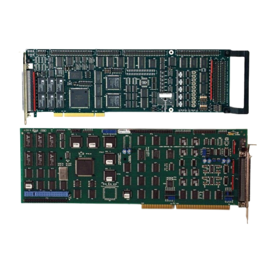
Aerotech UNIDEX 500 Operation & Technical Manual (617 pages)
MOTION CONTROLLER
Brand:
Aerotech
| Category:
Controller
| Size: 7 MB
Table of Contents
Table of Contents
4
Chapter 1: Introduction
32
Overview of the UNIDEX 500 System
32
The UNIDEX 500 Family of Controllers
32
The UNIDEX 500 Base Model (U500)
33
Figure 1-2. the UNIDEX 500 Family of Controllers
33
The UNIDEX 500 Plus Model (U500PLUS)
34
The UNIDEX 500 Ultra Model (U500ULTRA)
34
Ordering Information
34
Table 1-1. Available PC Bus-Based Motion Controllers in the UNIDEX 500 Series
34
Options and Accessories
36
Safety Procedures and Warnings
37
Introduction
37
Inspection of the UNIDEX 500 Control Board
39
Chapter 3: Software Installation and Fundamentals
40
Introduction
40
Minimum Hardware Requirements and Recommended System Configurations
40
Table 3-1. Minimum Hardware Requirements and Recommendations
40
Standard Installation Using Windows NT 4.0 or 95
41
Installing the UNIDEX 500 PC Board
42
Figure 3-1. Software Menu Available after Completed Installation
42
Software Startup
43
U500 ISA Base Address Jumpers (JP4, JP5, JP6, JP7, JP8, and JP9)
43
Configuring the Software to Match the Hardware
44
Configuration of the Software for the ISA Board
45
Configuring the Software for the PCI Board
45
Figure 3-3. Board 1 (U500 Registry Editor)
45
Initializing the U500 Board
46
Figure 3-4. the Edit Project File Popup
46
Figure 3-5. the Axis Position Window
47
Software Configuration Considerations
48
Configuring Key Parameters
48
Special Startup Considerations
50
Figure 3-6. Parameter Window
50
Figure 3-7. the Diagnostics Popup Window
51
Figure 3-8. the Diagnostics 2 Popup Window
52
Figure 3-9. the Axis Position Display
53
Figure 3-10. Flowchart Summary of the Installation/Configuration Process
53
Feedback Verification
54
Limit Verification
54
Preliminary Servo Loop Setup
54
Table 3-4. Servo Loop Tuning Parameters
55
Chapter 4: The Software Interface
56
Introduction
56
The File Menu
57
Table 4-1. File Menu Commands
57
The Project
58
The Parameters
58
The Firmware
58
The Load Program
58
The Reset Option of the File Menu
59
The Exit Option of the File Menu
59
The Edit Menu
59
The Project
59
Table 4-2. Edit Menu Commands
59
The Parameters
60
Table 4-3. Components of the "Edit Project File" Popup
60
Edit Parameters: the File Submenu
61
Edit Parameters: the Number, Value, and Axis Fields
61
System Options
62
Figure 4-5. Abort Options Tab of the MMI System Options Screen
66
Figure 4-6. LZR Setup Tab of the MMI System Options Screen
67
Figure 4-7. FPGA Setup Tab of the MMI System Options Screen
68
The Program Option of the Edit Menu
69
The Tools Menu
70
The Diagnostics Option of the Tools Menu
70
Figure 4-8. the Diagnostics Window
70
Table 4-5. Tools Menu Commands
70
Table 4-6. Software Status Diagnostics
72
Table 4-7. Axis Position Diagnostics
72
The Demo Option of the Tools Menu
74
The Axis Tuning
75
Axis Scope: the File Submenu
75
Table 4-9. Menu Items on the Axis Scope Screen
75
Table 4-10. File Submenu Options in Axis Scope
75
Axis Scope: the Plot Submenu
76
Table 4-11. Plot Submenu Options in Axis Scope
76
Axis Scope: the Trigger Submenu
77
Axis Scope: the Collect Submenu
78
Figure 4-10. Reverse Motion
78
Figure 4-11. Sample Rate Popup Window
78
Axis Scope: the Display Submenu
79
Axis Scope: the Axis Submenu
79
Axis Scope: the Units Submenu
80
Axis Scope: the Tools Submenu
80
Figure 4-14. Axis Submenu of the Axis Scope Screen
80
Figure 4-15. Units Submenu of the Axis Scope Screen
80
Figure 4-16. Tools Submenu of the Axis Scope Screen
81
Figure 4-17. Cursors Tool Bar of the Axis Scope Screen
81
Figure 4-20. Gains Toolbar of the Axis Scope Screen
83
Figure 4-21. Frequency Response Toolbar of the Axis Scope Screen
83
Figure 4-22. FFT Toolbar of the Axis Scope Screen
84
Table 4-13. File Submenu Options of the FFT Screen
84
Table 4-14. Plot Submenu Options of the Axis Scope Screen
84
The Joystick Digitizing Option of the Tools Menu
86
Figure 4-23. U500 Joysticks
86
Figure 4-24. Joystick Digitizing Window
87
The "Diagnostics 2" Option of the Tools Menu
88
The Variable Watch Option of the Tools Menu
89
The Windows Menu
90
The Functions Option of the Windows Menu
90
Table 4-15. Windows Menu Commands
90
The F2 Abort Button
91
The F3 Pause/Resume Button
91
The F4 Load Button and the Program Display Window
91
Figure 4-28. Program Control Window after F4 Load of UNTITLED.PRG
92
The F5 Jog Button
93
Password Protection
94
Figure 4-29. the F5 Jog Window
94
Figure 4-30. System Password Prompt Window
95
Figure 4-31. System Password Window
95
The F7 Diag Button
97
The F8 Fault Ack Button
97
The F9 Reset Button
97
The Status Option of the Windows Menu
98
Figure 4-32. the Software Status Bar
98
Table 4-17. Cell Descriptions of the Status Bar
99
The Jog Option of the Windows Menu
100
The Gain Adjust Option of the Windows Menu
100
The MDI Option of the Windows Menu
100
Figure 4-34. the Gain Adjust Popup
100
Figure 4-35. the MDI (Manual Data Interface) Window
100
The MFO Option of the Windows Menu
101
The Axis Display Option of the Windows Menu
101
Figure 4-36. the MFO Adjust Popup
101
Table 4-18. Axis Display Options
102
The Functions Menu
103
Figure 4-39. the Functions Menu
103
The Help Menu
104
Figure 4-40. the Help Menu
104
Figure 4-41. the about Popup Window
105
Chapter 5: Parameters
106
Introduction
106
The Edit Parameters Window
106
The Menu Bar of the Edit Parameters Window
107
The Parameter Tabs
107
The Scrollable Parameter Display Window
107
The Parameter Number Field
107
The Parameter Value Field
108
Axis Number Radio Buttons
109
The Position Tracking Tab
110
Table 5-1. Position Tracking Parameters (Tab 0)
110
Keep Axis Position after Reset (Y/N)
111
Axis N Rollover Machine Steps for Axes 1-4
112
Figure 5-3. Axis N Rollover in Rotary Stage Application
112
PSO Mailbox Dual_Port RAM Base Address
113
PSO-HOST and PC Interface Address (U500 ISA - 16 Bit MMI Software Only)
114
Table 5-5. Commonly Used Settings for the Host Base Address Parameter
114
Plane N Metric System (Y/N)
115
Metric Mode Number of Decimal Digits (1-8)
116
English Mode Number of Decimal Digits (1-8)
117
The Advanced Motion Tab
118
Table 5-10. Advanced Motion Parameters (Tab 1)
118
Overview of Planes
119
Number of Contour Planes (1, 2, 4)
122
Axis N Map to Plane {1-4} as {X, Y, Z, U
124
Axis N Gantry {Y/None}, Slave {1, 2, 3, 4
125
Figure 5-7. Using Home Offset Parameter to Keep Gantry Aligned after
127
Plane N Indexing Segment Time (1-20 Ms)
128
Linear Type Ac/De (Y/N)
129
Clamp Feedrate (Program Steps/Ms)
130
Corner Rounding Non-Ramp Time (1-32,000 Ms)
131
Figure 5-9. Sample Motion Path Shown with and Without Corner Rounding
131
Figure 5-10. Sample of Non-Ramp Time Overlap for Corner Rounding
131
Contouring Mode
133
A/D Channel N Joystick Deadband
134
Table 5-19. Joystick Deadband Parameters
134
A/D Channel N Joystick Center Position
135
Safe Zone Output Bit (0-8)
135
Table 5-20. Joystick Center Position Parameters
135
Option Board Setup Code
136
User Interrupt Setup Code
137
Abort on Input High (0, 1-16)
137
The Basic Motion Tab
138
Table 5-24. Basic Motion Parameters (Tab 2)
138
MFO, 0 no MFO-Pot, 1-255 Pot Offset
139
Figure 5-12. MFO Potentiometer with and Without Offsets
139
Plane N Contour Ramping Time (Ms)
140
Figure 5-13. Contour Ramping (Acceleration/Deceleration) Time
140
Contour Feedrate (Program Steps/Ms) for Plane N
141
X, Y, Z, and U Axes' Point-To-Point Feedrates (Program Steps/Ms) for Plane N
141
Table 5-28. Point-To-Point Feedrate Parameter Assignments and Settings
141
The Homing and Limits Tab
142
Table 5-29. Homing and Limits Parameters (Tab 3)
142
The Home Cycle
143
Figure 5-14. Home Cycle
144
Home Direction Is CCW (Y/N)
145
Figure 5-15. Typical Stage Showing CW and CCW Motor Rotation
145
Table 5-30. Settings for Parameter X02
145
Home Switch Normally Open (Y/N)
146
Table 5-31. Settings for Parameter X03
146
Power-On Home Feedrate (Machine Steps/Ms)
147
Table 5-32. Settings for Parameter X04
147
Normal Home Feedrate (Machine Steps/Ms)
148
Home Offset (Machine Steps)
148
Table 5-33. Settings for Parameter X05
148
Table 5-34. Settings for Parameter X06
148
Home Switch to Marker (Machine Steps) - U500 ISA Only
149
Home/Limit Switch Debounce (Ms)
150
Limit Switch Normally Open (Y/N)
150
Table 5-36. Settings for Parameter X08
150
Table 5-37. Settings for Parameter X09
150
Switch to Mechanical Stop (Machine Steps)
151
CCW Software Limit (Machine Steps)
151
CW Software Limit (Machine Steps)
151
Table 5-38. Settings for Parameter X22
151
Enable Vel/Accel Feedforward During Home (Y/N)
152
Table 5-39. Settings for Parameter X23
152
Table 5-40. Settings for Parameter X73
152
Use Home Limit During Home Cycle (Y/N)
153
Safe Zone Limits (Machine Steps)
153
Home/Limit Switch Debounce (Steps)
154
Home Marker Search Speed (Machine Steps/Ms)
154
The Traps Tab
155
Table 5-45. Trap Parameters
155
Max Ac/De (Machine Steps/Ms/Ms)
156
Table 5-46. Settings for Parameter X16
156
Top Feedrate (Machine Steps/Ms)
157
Max Velocity Error (0-8,388,607)
158
Table 5-48. Settings for Parameter X18
158
Max Position Error (0-8,388,607)
159
Max Integral Error (0-8,833,607)
160
RMS Current Trap (0-100%)
161
Figure 5-16. Sample RMS Current Maximums
161
Table 5-51. Settings for Parameter X48
162
RMS Current Sample Time (1-16,383 Ms)
163
Clamp Current Output (0-100%)
164
Table 5-53. Settings for Parameter X53
164
Output Bit for aux OUTPUT
165
Drive Fault Signal Active Low
166
AUX OUTPUT Active High
166
Table 5-55. Settings for Parameter X70
166
Table 5-56. Settings for Parameter X84
166
The Motor and Feedback Configuration Tab
167
Table 5-57. Motor Feedback Parameters
167
Introduction to Motors and Feedback Configurations
168
Table 5-58. Summary of General Purpose Inputs
172
Motor Feedback and Configuration Parameters
176
Table 5-64. Motor Feedback and Configuration Parameters
176
Primary/Position Feedback Channel
177
Encoder Gantry Mode
178
Table 5-66. Encoder Gantry Mode Configuration Parameters
179
Secondary/Velocity Feedback Channel
180
Table 5-67. Settings for Parameter X39
180
Primary Feedback Setup Code
181
Secondary Feedback Setup Code
181
Table 5-68. Settings for Parameter X40
181
Table 5-69. Settings for Parameter X41
181
Drive (Motor) Type (0-DC Brush, 1-AC Brushless, 2/3-Stepper)
182
Table 5-70. Settings for Parameter X42
182
AC Brushless Motor Commutation Factor (Cycles/Rev)
183
Encoder Feedback (Steps/Rev/(*4))
184
AC Brushless Motor Phase Offset (Degrees)
184
Stepper High Current (0-100%)
185
Stepper Low Current (0-100%)
185
Stepper Microstepping Resolution (Steps/Rev)
185
Stepper Encoder Verification (Y/N)
186
Stepper Encoder Speed (Microsteps/Ms)
186
AC Brushless Motor Phase Advance Base Speed (Steps/Ms)
187
Figure 5-18. Phase Advance Slope
187
AC Brushless Motor Base Speed Advance (Degrees)
188
AC Brushless Motor Phase Speed (Steps/Ms)
188
AC Brushless Motor Phase Speed Advance (Degrees)
188
Current Command Offset Parameters (MV)
188
Encoder Multiplication
188
Table 5-73. Settings for Parameters X79 and X80
188
Table 5-74. Settings for Parameter X82
188
The Servo Loops Tab
189
Table 5-75. Servo Loop Parameters (Tab 6)
189
Notch Filter (Y/N)
190
Kpos (0-8,388,607)(Position Loop Gain)
190
Ki (0-8,388,607)(Velocity Loop Integrator)
190
Kp (0-8,388,607)(Velocity Loop Proportional Gain)
191
Vff (0-8,388,607)(Velocity Feed Forward)
191
Aff (0-8,388,607)(Acceleration Feed Forward)
191
Notch Filter Coefficient N0, N1, N2, D1, and D2
192
The Notch Filter
192
Figure 5-19. U500 Filter Utility
192
Notch Filter Example
194
The Second Order Low Pass Filter
196
Servo Loop Update Rate (1-100) X 0.25 Ms
197
Servo Loop Type
197
Filter Time Constant
198
Table 5-79. Settings for Parameter X83
198
The Other Tab
199
Table 5-80. Other (Miscellaneous) Parameters (Tab 7)
199
Metric (X00) and English (X01) Conversion Factors
200
Positive (+) Move Is Clockwise (Y/N)
203
Positive (+) Jog Is same Direction as + Move (Y/N)
204
Pause Enable in Freerun (Y/N)
204
Table 5-83. Settings for Parameter X12
204
Table 5-84. Settings for Parameter X13
204
MFO Enable in Freerun (Y/N)
205
Calibration Enable (Y/N)
205
In Position Deadband (Machine Steps)
206
Table 5-86. Settings for Parameter X35
206
Backlash (Machine Steps)
207
Table 5-87. Settings for Parameter X37
207
Joystick: High Speed (Machine Steps/Sec)
208
Joystick: Low Speed (Machine Steps/Sec)
208
Table 5-88. Settings for Parameter X50
208
Table 5-89. Settings for Parameter X51
208
Absolute Mode Scale (Machine Steps)
209
Orthogonality Correction Table Enabled (Y/N)
209
2-D Error Mapping Enabled (Y/N)
210
Reverse Joystick Direction
210
The Faults Tab
211
Introduction to Fault Masks
211
Table 5-93. Fault Mask Bit Descriptions
212
Error Mask Fault
213
Disable Axis
213
Interrupt PC
213
Aux Output
214
Halt Queue
214
Abort Motion
214
Enable Brake
215
The General Tab
216
The Axis Tab
217
Chapter 6: Tuning Servo Loops
219
The Axis Scope Toolbars
219
Figure 6-2. Axis Scope Toolbars
219
Kp Proportional Gain
220
Ki Integral Gain
220
Kpos Position Gain
220
Vff Velocity Feedforward Gain
220
Aff Acceleration Feedforward Gain
220
Autotuning
221
Setting up an Excitation
221
Specifying Desired Performance
221
Bandwidth and Damping
221
Procedure
222
Figure 6-4. Autotune Plot Where "Steps" Has Been Set too Low
223
Figure 6-5. Autotune Plot Where "Steps" Has Been Set too High
224
Figure 6-6. Autotune Plot Showing Proper Calibration
224
Dual Loop Systems
225
Guidelines and Limitations
225
Manual Tuning Procedure for Servo Loops
226
Figure 6-7. Flowchart of Overall Tuning Process
227
Figure 6-8. the Edit Parameters Window
228
Figure 6-9. Servo Loop Tab of the Edit Parameters Window
229
Figure 6-10. Maximize Button on the Axis Scope Window
229
Table 6-1. Initial Servo Parameter Values
229
Figure 6-11. Unacceptable Velocity Error
231
Figure 6-12. Acceptable Velocity Error (When Adjusting Kp)
231
Figure 6-13. Unacceptable Position Error (When Adjusting Ki)
232
Figure 6-14. Plot Showing an Appropriate Value for Kpos
233
Figure 6-15. Plot Showing Overall Effects When Kpos Is High
234
Figure 6-16. Plot Showing Aff Adjustment
235
Tuning Tips
236
Figure 6-17. Tuning Plot of an AC Brushless Motor
236
Tachometer Feedback Basics
237
In-Position Integrator
237
Velocity Feed Forward
237
Servo Parameter Setup for Tachometer Feedback
237
The Axis Scope Toolbars
238
Kpos Position Gain
238
Ki In-Position Integrator
238
Vff Velocity Feedforward Gain
238
Kp Proportional Gain
238
Aff Acceleration Feedforward Gain
238
Table 6-2. Servo Gain Values
238
Tuning Tachometer Loops
239
Figure 6-19. the Edit Parameters Window
241
Figure 6-20. Servo Loop Tab of the Edit Parameters Window
242
Table 6-3. Initial Servo Parameter Values - Tach Tuning
242
Figure 6-24. Plot Showing a Roughly Tuned Axis (When Adjusting Kpos)
246
Figure 6-25. Plot Showing the Removal of DC Offsets in the Position Error
247
Figure 6-27. Plot Illustrating Smoothness in the Position Error
248
Figure 6-28. Plot Showing Effects on Position Error (When Ki Is too High)
249
Figure 6-29. Plot of the Position Error with Appropriate Ki Value
250
Figure 6-30. Position Error after Increasing Vff
251
Figure 6-31. Position Error Reduced to Within 10 Counts of Error Using Vff
251
Figure 6-32. Plot of Position Error When Vff Is too High
252
Chapter 7: Programming Commands
254
Introduction
254
Table 7-1. Programming Conventions Used in this Manual
254
Program Execution Levels
255
Board Level Execution
255
C Library Interface
255
C Library ASCII Interface
255
Table 7-2. Single Character Arguments for Programming
255
Mathematical Function Commands
256
Direct Variables (V0 through V255)
256
Indirect Variables (VV0 through VV255)
256
Functions
256
Table 7-3. Supported Functions
257
Operators and Evaluation Hierarchy
258
System Registers
259
Relative Position Registers
259
Absolute Position Registers
259
Real Time Feedback Position Registers
260
Real Time Commanded Position Registers
260
Table 7-7. Real Time Feedback Position Registers
260
Table 7-8. Real Time Commanded Position Registers
260
Understanding the Concept of Program Steps
261
A/D Channel Registers
261
System Inputs $INP and $IN0-$INF
263
Isbx I/O Interface (Optional on U500 ISA Only)
264
Table 7-11. ISBX Control Word Configurations
265
4EN Expansion Board I/O Interface (Optional on U500 ISA Only)
267
Table 7-12. 4EN I/O Connector Interface
267
Table 7-13. U500 Programming Command Summary
268
Programming Commands
268
Abort
275
Acceleration
275
AC PL (Accel Plane)
276
AFCO (Auto Focus)
276
Table 7-15. Analog Input Locations
279
Again
280
Analog Vector Tracking Mode
281
Table 7-16. Arguments for Analog Command
281
AT (Autotune)
283
Board
284
Brake
285
CAL (Load Calibration File)
286
Calldll
287
CLOCKWISE and COUNTERCLOCKWISE
290
Circular Interpolation
290
Figure 7-1. Circle Center Adjustment
293
CLRSCR (Clear Screen)
295
CM (Contouring Mode)
295
Com Free
296
Com Get
296
Com Init
298
Com Receive
298
Com Send
299
Com Set
300
Com Set
302
Com Set
303
CS (Command Scope)
304
Cutter Compensation Commands
305
Figure 7-2. Startup Moves
306
Figure 7-3. Ending Moves
306
CVI (Convert to Integer)
308
Cycle
309
DAC (D/A Output)
310
Disable
311
DS (Display Servo Loop Data)
312
Dwell
313
DY (Dynamic Gain)
313
Enable
316
Error
317
Exit
318
Fault Acknowledge
319
FL (Filter Time Constant)
319
Freedll
320
Freerun
321
Gain
322
Gear
323
Goto
324
Halt
326
Home
327
Table 7-17. Comparison Operators
329
Immediate
330
Index
331
Inn (Read Inputs)
332
Interrupt
333
Io Command
334
Ioset Command
334
Jog
335
Label Marker (:)
335
Linear
336
Loaddll
337
Figure 7-7. Sine-Type Ramp
337
Loop
338
Lvdt
339
M0 ("M Zero")
340
MCOMM (Motor Commutation)
341
Message
342
MR (Memory Read)
343
MSET (Motor Setup)
344
Table 7-18. Motor Phase Labels and Hall States
345
MW (Memory Write)
347
Next
348
Oen (Extended Output)
349
Output
350
Parallel
351
Prm (Parameter Read)
352
Pause
353
Figure 7-9. PAUSE Function
353
Plane
354
Plc
355
Position Command (in Position)
358
Program
359
Queue
361
Ramp
363
Reference
364
Return
364
ROTATE (Part Rotation)
365
Rounding
366
Scope
369
SCF (Overriding Scale Factor)
370
Slave
372
Table 7-20. Setting for the 'Flags' Argument of the Slave Command
373
Slew
377
Figure 7-12. Optional UNIDEX 500 Joysticks (JBV Model Left, JI Model Right)
377
Software
379
Spline
381
Start
382
Subroutine
383
Sync
383
Target Tracking Commands (TE, TD, TP)
384
Trajectory
385
Trigger
386
UMFO (Manual Feed Override)
386
VAR (Read/Write Variables)
387
Velocity
388
1.Correct Usage and Limitations of the Velocity Profiling Algorithm in Contour Mode 0 (CM0)
389
Figure 7-18. same Motion with Ramping Time Reduced
391
Figure 7-19. Circular Profiling with Long Ramp Time
392
Figure 7-20. Circular Profiling with Short Ramp Time
392
2.CM1 Contouring Mode
393
Figure 7-21. Two Axis Linear Move with Velocity Profiling
393
Figure 7-23. Velocity Profile with Digital Filter
395
Figure 7-24. Velocity Profile Without a G9 Command at the End of the Sequence
396
Wait
397
While/Endwhile
398
Chapter 8: U500 Pci Pulse Output
400
Hardware Configuration
400
Table 8-1. Opto Coupler Options
400
Pulse Output Programming
401
Single PSO Mode
401
Table 8-2. Arguments for the FIRE Command
402
Array Download
404
Window Comparators
406
Table 8-4. Arguments for Window Command
406
Dual Axis PSO Mode
409
Figure 8-2. Single PSO Mode Block Diagram
411
Figure 8-3. Dual PSO Mode Block Diagram
412
U500PCI/PSO-PC Functionality
413
Chapter 9: Sample Programs
415
Incremental (Relative) Motion with Velocity Profiling
415
Figure 9-1. Sample Path for Incremental (Relative) Motion Demonstration Using Velocity Profiling
415
Absolute Motion with Velocity Profiling
418
Figure 9-2. Sample Path for Absolute Motion Example Using Velocity
418
CNC Demonstration Using Velocity Profiling, Linear, and Circular Interpolation
420
Corner Rounding
421
Figure 9-3. Sample Path of Square with and Without the Rounding Feature
421
GEAR Demonstration of a Master Axis with Two Slave Axes
423
Interlocking Contour Planes
424
Splining
425
Programming Using Inputs
426
Part Rotation
427
Overriding Scale Factor
429
Figure 9-6. Output from Overriding Scale Factor Example Program
431
COM Functions
432
Chapter 10: Programming Tools
434
Introduction
434
Summary of the UNIDEX 500 Quick Library Functions (32Bit)
435
Overview
435
Device Driver Information
435
Registry Information
436
Table 10-2. Quick Library Functions
437
Arguments and Return Values for the Aerq_Read_Status Function
451
Table 10-3. Arguments and Return Values for the Aerq_Read_Status Function
451
Programming Example
454
Summary of the UNIDEX 500 WAPI Functions (32 Bit)
464
Overview
464
Device Driver Information
464
Registry Information
465
WAPI Library Functions
466
Table 10-4. WAPI Library Functions
466
Arguments and Return Values for the Wapiaerreadstatus Function
473
Table 10-5. Arguments and Return Values for the Wapiaerreadstatus Function
473
Example File for U500 "WAPI" Library
476
Chapter 11: Utility Programs
480
Introduction
480
The AERVER.EXE Utility (32 Bit Software Only)
480
The DSPDMP32.EXE Program (32 Bit Software Only)
481
Chapter 12: Technical Details
482
Technical Details Common between U500 PCI and ISA Cards
482
Encoder Signal Specifications
482
1.Differential Encoders
482
Figure 12-1. Electrical Characteristics of a Single Ended Encoder Interface
483
Table 12-1. Termination Resistor Configuration for Axis 1 Encoders
485
Table 12-2. Termination Resistor Configuration for Axis 2 Encoders
485
Table 12-3. Termination Resistor Configuration for Axis 3 Encoders
486
Table 12-4. Termination Resistor Configuration for Axis 4 Encoders
486
Encoder Signal Pinouts
487
Limit and Amplifier Fault Inputs
488
Table 12-6. Limit and Amplifier Fault Inputs
488
Current Command Output
489
Figure 12-3. Electrical Characteristics of the UNIDEX 500 Limit Interface
489
Digital Input Bus Specifications
490
Table 12-7. Current Command Output Signals and Pin Locations
490
Figure 12-5. Electrical Characteristics of the UNIDEX 500 Input Bus Interface
491
Output Bus Specifications
492
Table 12-9. UNIDEX 500 Output Pinouts
492
The Brake Output
493
Figure 12-6. Example Optocoupled Output Bus Interface
493
Figure 12-7. Electrical Characteristics of the UNIDEX 500 Brake Signal Output
494
Table 12-10. UNIDEX 500/Opto 22 Connection Information
495
Figure 12-8. Electrical Characteristics of the UNIDEX 500 Opto
497
Figure 12-9. Electrical Characteristics of the UNIDEX 500 Opto 22 Connections
498
Table 12-12. Analog Input Locations for the UNIDEX 500 ISA
500
Opto 22 I/O Hall Inputs (P5) Pinouts
501
Table 12-13. Pinouts for Opto 22 I/O Hall Inputs (P5)
501
UNIDEX 500 ISA Technical Details
502
Test Points
502
Table 12-14. Motor Related Test Points
502
Jumper Configurations
504
1.Marker Pulse Qualification Jumpers
505
Table 12-19. Amplifier Enable Jumper Settings
507
Table 12-20. PC Bus Interrupt Jumper Settings
509
Jumpers JP16 - JP24)
510
Table 12-23. Base Address Jumper Settings
513
Emergency Stop Input
514
Figure 12-12. Electrical Characteristics of the UNIDEX 500 Emergency Stop Interface
514
Isbx Connector Pinout (P4)
515
DSP Bus Pin Description (P3)
516
Table 12-26. DSP Bus Pinouts
516
Encoder Interface between U500 and PC-PSO (P6)
517
Motorola DSP56002 Once Port (P8)
517
Table 12-27. Pinouts for the Encoder Interface to the PC-PSO
517
Table 12-28. Once Port Pinouts (P8)
517
UNIDEX 500 PCI Technical Details
518
Emergency Stop Input
518
U500 PCI Analog Inputs
518
CLK/DIR Stepper Mode
519
Table 12-30. Allowable Combinations for U500 BASE/PLUS
519
Table 12-31. Allowable Combinations for U500 ULTRA
519
Figure 12-14. CLK/DIR Schematic
520
Figure 12-15. U500 PCI CLK/DIR Stepper Section
520
Additional D/A Outputs
521
U500 PCI D/A Analog Outputs
521
Figure 12-16. U500 PCI D/A Output Diagram
522
Table 12-34. Isolated System Jumpers (External Power Supply Required)
522
Table 12-35. D/A Output Specifications
522
Figure 12-17. U500 PCI Connection to BB500 (Isolated)
523
Figure 12-18. U500 PCI Connection to BB500 (Non-Isolated)
524
Figure 12-19. U500 PCI Connection to BB501 (Isolated)
525
Figure 12-20. U500 PCI Connection to BB501 (Non-Isolated)
526
U500 PCI Test Points
527
U500 Specifications
528
U500 PCI Jumpers
528
Connector Pinouts
530
Table 12-39. P1 - Main Connector Pinouts
530
Table 12-40. P3 - Expansion Connector Pinouts
531
Table 12-41. P4 - 8X3 IO Connector Pinouts
532
4.P5 - 16In 8 out
533
Table 12-42. P5 - 16 in 8 out (Optional Hall Inputs)
533
Inputs )
534
Encoder/Miscellaneous Interface
534
Table 12-44. P8 - ½ Secondary Axis Interface Pinouts
535
Table 12-45. P9 - ½ Secondary Axis Interface Pinouts
536
Figure 12-21. U500 PCI Board
537
Table 13-1. Troubleshooting for Common Installation, Startup, and Communication Problems
539
Chapter 13: Troubleshooting
540
Stepper Motors and Related Problems
540
Table 13-2. Troubleshooting for Stepper Motors (and Related) Problems
540
Servo Related Problems
541
Problems Involving Fault Conditions
542
Table 13-4. Troubleshooting for Problems Involving Fault Conditions
542
Homing Related Problems
544
Table 13-5. Troubleshooting for Homing Related Problems
544
General UNIDEX 500 Questions
545
Appendix A: Glossary of Terms
548
Appendix B: Warranty and Field Service
558
Appendix C: Parameter Summary
560
Table C-1. General Parameters
560
Table C-3. Axis Parameters
564
Appendix D: Rev_ Board Technical Details
570
Introduction
570
Test Points
570
Jumper Configurations
570
Encoder Signal Specifications
570
Table D-1. Motor Related Test Points
570
Table D-3. DSP 56001 Chip Test Points
571
Table D-4. Miscellaneous Test Points
572
Table D-5. PC Base Address Jumper Settings
572
Differential Encoders
574
Single Ended Encoders
575
Figure D-2. Electrical Characteristics of a Single Ended Encoder Interface
575
Software Setup for Single-Ended Encoders
576
Aerotech Stepper Motors with the Home Marker Option
576
Table D-8. Termination Resistor Configuration for Axis 2 Encoders
578
Table D-9. Termination Resistor Configuration for Axis 3 Encoders
578
Table D-10. Termination Resistor Configuration for Axis 4 Encoders
578
Encoder Signal Pinouts
579
Table D-11. Encoder Signals and Pinouts
579
Amplifier Enable Outputs
580
Figure D-4. Electrical Characteristics of the UNIDEX 500 Amplifier Enable
580
Table D-12. Amplifier Enable Output Locations
580
Appendix E: Setting up an Ac Brushless Motor with the
584
Introduction
584
Setup Procedure
584
Figure E-1 U500 Diagnostic Window
586
Table E-1.Hall State Table
587
Appendix F: Unidex 500 Applications
590
Using the Encoder Position Capture Input - "UINT_N
590
Additional UINT Features on the U500 PCI Card
590
Appendix G: U500 Calibration Option
594
Introduction
594
Axis Calibration
594
Orthogonality Correction
594
Error Mapping
594
Table G-1. Sample Calibration Data
597
Figure G-3. Sample Multi-Row Orthogonality Correction File
599
Figure G-6. 2D Correction Grid
603
Figure G-7. 2D Correction Interpolation
604
Advertisement
Advertisement
Related Products
Aerotech UNIDEX 511
Aerotech UNIDEX U100i
Aerotech UNIDEX 100
Aerotech UNIDEX 600 Series
Aerotech UNIDEX 650
Aerotech UNIDEX 11
Aerotech LaserTurn 5-ASR
Aerotech 6020HRJ
Aerotech 8030J
Aerotech A3200 Series
Aerotech Categories
Industrial Equipment
DC Drives
Controller
Engine
Amplifier
More Aerotech Manuals
Login
Sign In
OR
Sign in with Facebook
Sign in with Google
Upload manual
Upload from disk
Upload from URL