Siemens SIPROCESS GA700 Compact Operating Instructions
Continuous gas analysis
Hide thumbs
Also See for SIPROCESS GA700:
- Operating manual (306 pages) ,
- Operating instructions manual (224 pages) ,
- Compact operating instructions (208 pages)
Table of Contents
Advertisement
Quick Links
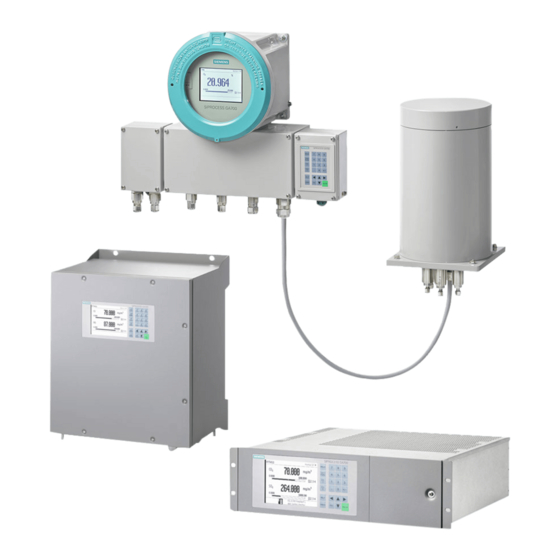
Continuous gas analysis
SIPROCESS GA700
Devices in explosion-proof design
Compact Operating Instructions
7MB3000-.....-....
7MB3010-.....-....
7MB3020-.....-....
7MB3040-.....-....
01/2022
A5E35134047-11
Introduction
Safety instructions
General information
Installing
Connecting
Commissioning
Service and maintenance
Dismantling and disposal
Technical specifications
Appendix A
1
2
3
4
5
6
7
8
9
A
Advertisement
Table of Contents

Related Manuals for Siemens SIPROCESS GA700


Summary of Contents for Siemens SIPROCESS GA700
- Page 1 Introduction Safety instructions General information Continuous gas analysis Installing SIPROCESS GA700 Devices in explosion-proof design Connecting Commissioning Compact Operating Instructions Service and maintenance Dismantling and disposal Technical specifications Appendix A 7MB3000-..-..7MB3010-..-..7MB3020-..-..7MB3040-..-..01/2022 A5E35134047-11...
- Page 2 Note the following: WARNING Siemens products may only be used for the applications described in the catalog and in the relevant technical documentation. If products and components from other manufacturers are used, these must be recommended or approved by Siemens. Proper transport, storage, installation, assembly, commissioning, operation and maintenance are required to ensure that the products operate safely and without any problems.
-
Page 3: Table Of Contents
Table of contents Introduction ............................7 Purpose of this document ....................7 History..........................7 Purpose ..........................7 Field of application ......................8 Date of manufacture ......................10 Qualified personnel for applications in hazardous areas ............11 Delivery ..........................11 Transportation and storage ....................12 Warranty conditions...................... - Page 4 Table of contents 4.5.1 Device-specific safety instructions..................31 4.5.2 Installing the wall-mounted device..................32 Connecting ............................35 Gas connections ........................ 35 5.1.1 General safety instructions....................35 5.1.2 Safety instructions for hazardous areas................36 5.1.3 Connection information ..................... 36 5.1.4 Arrangement of the gas connections in the rack-mounted device........37 5.1.5 Arrangement of the gas connections in the wall-mounted device ........
- Page 5 Table of contents Service and maintenance ........................75 General safety instructions....................75 Safety instructions for hazardous areas................77 7.2.1 Loss of explosion protection ....................77 7.2.2 Absence of pre-purging...................... 77 7.2.3 Opening the device in energized state................78 7.2.4 Dust in pressurized enclosure "Type of protection Ex p" ............79 7.2.5 Securing plug-in connections .....................
- Page 6 Table of contents Devices in explosion-proof design Compact Operating Instructions, 01/2022, A5E35134047-11...
-
Page 7: Introduction
Introduction Purpose of this document These compact operating instructions are a brief summary of important features, functions and safety instructions, and contains all information required for safe use of the device. These are instructions on mounting, connecting, commissioning, operation, servicing, dismantling and decommissioning of the device. -
Page 8: Field Of Application
"References (Page 107)". Field of application These compact operating instructions describe SIPROCESS GA700 devices approved for operation in hazardous areas. They refer to the rack-mounted and wall-mounted devices with installed analyzer modules that are used depending on the measuring task and local conditions. - Page 9 The designation db is only used if at least one CALOMAT 7 7MB304x-2xxxx-xxxx module is installed. The designation op is is only used if at least one ULTRAMAT 7 7MB301x-2xxxx-xxxx or 7MB301x-3xxxx-xxxx module is installed. Table 1-1 SIPROCESS GA700 Ex devices with analyzer modules Device MLFB number Ignition protection type ATEX and IECEx certifi‐...
-
Page 10: Date Of Manufacture
Introduction 1.5 Date of manufacture Device MLFB number Ignition protection type ATEX and IECEx certifi‐ variant cates 7MB3000-xxxxx-xxGx II 2G Ex pyb db ib op is IIC T4 Gb (for gases that are Wall-mounted device: potentially explosive occasionally) 7MB301x-2xxxx-xxBx BVS 14 ATEX E 153 X II 3G Ex ec db ib nA nC op is IIC T4 Gc 7MB301x-3xxxx-xxBx IECEx BVS 14.0104X... -
Page 11: Qualified Personnel For Applications In Hazardous Areas
Introduction 1.7 Delivery 1963, 1983, 2003, 2023 1964, 1984, 2004, 2024 1965, 1985, 2005, 2025 1966, 1986, 2006, 2026 1967, 1987, 2007, 2027 1968, 1988, 2008, 2028 1969, 1989, 2009, 2029 In conformance with DIN EN 60062 The identifier of the manufacturing location (e.g. N1) is added as a prefix to the actual serial number Qualified personnel for applications in hazardous areas Persons who install, connect, commission, operate, service, maintain and dismantle the device... -
Page 12: Transportation And Storage
Introduction 1.8 Transportation and storage 4. Check the scope of delivery for correctness and completeness on the basis of the delivery note. Compare the serial numbers on the delivery note with the serial numbers on the basic device or on the modules. 5. -
Page 13: Warranty Conditions
All obligations on the part of Siemens AG are contained in the respective sales contract, which also contains the complete and solely applicable liability provisions. The provisions defined in the sales contract for the responsibility for defects are neither extended nor limited by the remarks in this document. - Page 14 Introduction 1.9 Warranty conditions Devices in explosion-proof design Compact Operating Instructions, 01/2022, A5E35134047-11...
-
Page 15: Safety Instructions
• Canadian Electrical Code (CEC) (Canada) Additional provisions for applications in hazardous areas are, for example: • IEC 60079-14 (international) • EN 60079-14 (EU) Additional information is available at: Certificates (https://support.industry.siemens.com/cs/ww/en/ps/17731/cert) Devices in explosion-proof design Compact Operating Instructions, 01/2022, A5E35134047-11... -
Page 16: Conformity With European Directives
Safety instructions 2.2 Improper device modifications 2.1.2 Conformity with European directives The CE marking on the device shows conformity with the regulations of the following European guidelines: Electromagnetic compatibili‐ Directive of the European Parliament and of the Council ty EMC 2014/30/EU of 26 February 2014 on the harmonization of the laws of the Member States relating to electromagnetic compatibility (new version) -
Page 17: For Use In Hazardous Areas
Safety instructions 2.3 For use in hazardous areas For use in hazardous areas WARNING Unsuitable device for the hazardous area Explosion hazard • Only use devices that have been approved for use in the intended hazardous area and are labeled accordingly. WARNING Use outside the permitted voltage limits Explosion hazard... - Page 18 Safety instructions 2.3 For use in hazardous areas Note Open the enclosure only in case of maintenance or service The enclosure must always remain closed during operation. • Keep the enclosure closed during operation. • Open the enclosure only for installation or maintenance. Close the enclosure after this work has been completed.
-
Page 19: General Directives For Explosion Protection
Safety instructions 2.4 General directives for explosion protection General directives for explosion protection 2.4.1 Internal explosion protection Internal explosion protection refers to the sample gas path (containment system "CS") in the analyzer and to the ignition protection of the process gas. A differentiation must be made between the following cases: Table 2-1 Internal explosion protection: Differentiation of cases... -
Page 20: Type Of Protection "Ex P
Safety instructions 2.4 General directives for explosion protection the technical data of the respective device version. The exact specifications of the sample gas inlet conditions can be found in the section "Technical specifications for operation in hazardous areas (Page 96)". Check the tightness of the containment system particularly prior to the introduction of flammable sample gases after all installation and maintenance work. -
Page 21: Type Of Protection Ex T
Safety instructions 2.4 General directives for explosion protection 2.4.2.3 Type of protection Ex t WARNING Explosion hazard Devices that are operated with the type of protection Ex t "Dust protection through enclosure" are not designed for introducing combustible gas mixtures. Otherwise, there is a danger of explosion. - Page 22 Safety instructions 2.4 General directives for explosion protection Devices in explosion-proof design Compact Operating Instructions, 01/2022, A5E35134047-11...
-
Page 23: General Information
10 seconds for older devices to switch over, and up to 100 seconds to switch to safe operating mode. If you are using SIPROCESS GA700 devices in critical processes, observe the following information: • Monitor the limits externally via the control system. -
Page 24: Measuring High Oxygen Concentrations
General information 3.3 Measuring high oxygen concentrations Measuring high oxygen concentrations WARNING Measuring gas mixtures with high oxygen concentration Explosion hazard Introducing non-flammable gas mixtures with an oxygen concentration of more than 21% can result in an accumulation of oxygen in increased concentration in the enclosure. There is a danger of explosion. -
Page 25: Installing
Note Material compatibility Siemens can provide you with support concerning selection of analyzer components wetted by the process medium. However, the device operator is responsible for the selection of components. Siemens accepts no liability for faults or failures resulting from incompatible materials. - Page 26 Installing 4.1 General safety instructions WARNING Violation of the maximum permissible operating pressure Danger of injury or poisoning The maximum permissible operating pressure depends on the device version. The device can be damaged if the maximum permissible operating pressure is exceeded. Hot, toxic and corrosive process media can be released.
-
Page 27: Safety Instructions For Hazardous Areas
Installing 4.2 Safety instructions for hazardous areas NOTICE Direct sunlight Device damage The device can overheat or materials become brittle through the influence of UV radiation. • Protect the device from direct sunlight. • Make sure that the maximum permissible ambient temperature is not exceeded. For more information on this, see section "Technical specifications (Page 83)". -
Page 28: Installation Instructions
Installing 4.3 Installation instructions Installation instructions Note Layout of the installation location The installation location should be: • Easily accessible • Shock-free and vibration-free • Within the ambient temperature limits Note Weatherproof installation Install the device at a location where it is protected against: •... -
Page 29: Rack-Mounted Device
Installing 4.4 Rack-mounted device Note Dimensioning of the purging gas outlet The following applies for the dimension of the minimum internal diameter and length of the purging gas outlet: • The permissible internal pressure in the enclosure may not be exceeded by the selected design. -
Page 30: Installing The Rack-Mounted Device
Installing 4.4 Rack-mounted device Note Installation in control cabinets • Make sure there is adequate ventilation between the devices when installing in control cabinets. • Make sure that the permitted ambient temperature listed in the technical specifications is not exceeded. 4.4.2 Installing the rack-mounted device Dimension drawing... -
Page 31: Wall-Mounted Device
Installing 4.5 Wall-mounted device Note As an option, you can place the rack-mounted device on a guide bracket or floor panel in a rack or cabinet. Wall-mounted device 4.5.1 Device-specific safety instructions WARNING Open cable inlet or incorrect cable glands Danger of explosion in hazardous areas •... -
Page 32: Installing The Wall-Mounted Device
Installing 4.5 Wall-mounted device 4.5.2 Installing the wall-mounted device Dimension drawing The following figure shows the dimensions of the wall-mounted device and the distance of the fastening holes. The dimensions are specified in millimeters. Figure 4-2 Drilling template and side view Devices in explosion-proof design Compact Operating Instructions, 01/2022, A5E35134047-11... - Page 33 Installing 4.5 Wall-mounted device Figure 4-3 Dimensions with open wall-mounted device Procedure 1. Drill four holes into the wall. The dimensions for the drill holes are specified in the drilling pattern. 2. Insert the anchors in the drilled holes. 3. Position the wall-mounted device on the wall and fasten it with the screws. Devices in explosion-proof design Compact Operating Instructions, 01/2022, A5E35134047-11...
- Page 34 Installing 4.5 Wall-mounted device Devices in explosion-proof design Compact Operating Instructions, 01/2022, A5E35134047-11...
-
Page 35: Connecting
Connecting Gas connections 5.1.1 General safety instructions WARNING Introduction of toxic, corrosive or flammable gases The limited release of toxic or corrosive gases during their introduction cannot be fully avoided. • Before toxic, corrosive or flammable gases are introduced, carry out a leak test for the pipe connections. -
Page 36: Safety Instructions For Hazardous Areas
Connecting 5.1 Gas connections 5.1.2 Safety instructions for hazardous areas DANGER Introduction of combustible media in OXYMAT 7 Explosion hazard The introduction of combustible media in OXYMAT 7 can lead to an explosion. • Install suitable flame arresters in the sample gas and reference gas paths directly at the device. -
Page 37: Arrangement Of The Gas Connections In The Rack-Mounted Device
Connecting 5.1 Gas connections Sample gas preparation The sample gas must be conditioned to prevent contamination of the parts through which it flows. We recommend the following minimum configuration: • Gas sampling device with filter • Sample gas cooler • Analyzer filter, medium pore size <10 µm Depending on the characteristics of the sample gas it may be necessary to provide additional equipment, for example, an external gas suction pump, washing bottle or pressure reducer. -
Page 38: Arrangement Of The Gas Connections In The Wall-Mounted Device
Connecting 5.1 Gas connections ① Slot of analyzer module 1: OXYMAT 7 Gas connections: Sample gas inlet Sample gas outlet not assigned Reference gas inlet ② Slot of analyzer module 2 CALOMAT 7 Gas connections: Sample gas inlet Sample gas outlet not assigned Not assigned Figure 5-1... - Page 39 Connecting 5.1 Gas connections ① Purging gas inlet ② Purging gas outlet ③ Slot of analyzer module 2: ULTRAMAT 7 Gas connections: Sample gas inlet Sample gas outlet Reference gas outlet Reference gas inlet Atmospheric pressure sensor ④ Slot of analyzer module 1: OXYMAT 7 Gas connections: Sample gas inlet Sample gas outlet...
- Page 40 Connecting 5.1 Gas connections Wall-mounted device with high-temperature analyzer modules The following figure shows the bottom of the wall-mounted device with gas connections of a high-temperature version of an OXYMAT 7. ① Purging gas inlet ② Purging gas outlet ③ Reference gas inlet ④...
- Page 41 Connecting 5.1 Gas connections ① Purging gas inlet ② Purging gas outlet ③ Slot of analyzer module 2: ULTRAMAT 7 Gas connections: Sample gas inlet Sample gas outlet Reference gas outlet Reference gas inlet Devices in explosion-proof design Compact Operating Instructions, 01/2022, A5E35134047-11...
-
Page 42: Purging Gas Connections
Connecting 5.1 Gas connections 5.1.5.2 Purging gas connections Overview ① Purging gas inlet ② Purging gas outlet Figure 5-4 Purging gas connections Design of the gas connections Dimensions of purging gas couplings Diameter Exterior 12 mm Length Without sealing caps 28 mm With sealing caps 41 mm... -
Page 43: Connecting Gas
Connecting 5.1 Gas connections Minimum requirements In principle, any Ex px, Ex py or Ex pz safety equipment with a prototype test certificate for hazardous areas can be used. This safety equipment must have at least the following features: • Safety level for monitoring: –... -
Page 44: Wall-Mounted Device With Analyzer Modules In Standard Version
Connecting 5.1 Gas connections 5.1.6.2 Wall-mounted device with analyzer modules in standard version Procedure 1. Connect the gas lines by means of suitable clamping ring screwed connections to the associated gas inlets and outlets. When tightening the union nuts at the screwed connections make sure that you counter properly. -
Page 45: Device With One Ultramat 7 Analyzer Module, High-Temperature Version
Connecting 5.1 Gas connections 5.1.6.4 Device with one ULTRAMAT 7 analyzer module, high-temperature version Overview ① Gas connections for sample and reference gas ② Cable glands clamping ring connections 6 mm (4 units) ③ Heated external sample gas and reference gas lines (not included in scope of delivery) Figure 5-5 ULTRAMAT 7 high-temperature version, connecting gas Procedure... -
Page 46: Further Information On The Gas Connection
Connecting 5.2 Electrical connections 5.1.7 Further information on the gas connection It is essential that you observe the following points for trouble-free operation: • When tightening the union nuts at the gas couplings, ensure that you counter properly in order to achieve a tight gas path. •... -
Page 47: Safety Instructions For Hazardous Areas
Connecting 5.2 Electrical connections WARNING Missing PE/ground terminal Danger of electrocution If there is no ground terminal, there is a risk of electrocution. Depending on the device version, connect the power supply as follows: • Power plug: Ensure that the used socket has a PE/ground terminal. Check that the PE/ground terminal of the socket and power plug match. - Page 48 Connecting 5.2 Electrical connections WARNING Unsuitable lines and/or cable glands Danger of explosion in hazardous areas • Only use lines and cable glands that are appropriate for the application. • Tighten the cable glands s in accordance with the torques specified in the section "Electrical connections (Page 46)".
-
Page 49: Connection Information
Connecting 5.2 Electrical connections WARNING Incorrect selection of type of protection Risk of explosion in areas subject to explosion hazard. This device is approved for several types of protection. 1. Decide in favor of one type of protection. 2. Connect the device in accordance with the selected type of protection. 3. -
Page 50: Requirements For Electrical Connection
Connecting 5.2 Electrical connections Note Electromagnetic compatibility (EMC) You can use this device in industrial environments and small businesses. Metal housings show increased electromagnetic compatibility compared to high-frequency radiation. The protection from high-frequency radiation can be increased by grounding the housing. Note Improvement of interference immunity •... - Page 51 Connecting 5.2 Electrical connections Overview ① Connector numbers ② Power supply unit: IEC connector with guard bracket ③ Processing unit, Ethernet with interlock and 37-pin sub-D (female), digital inputs and outputs ④ Optional module 1.1 25-pin sub-D (female), digital inputs and outputs or blank plate ⑤...
-
Page 52: Connecting The Power Supply
Connecting 5.2 Electrical connections 5.2.5.2 Connecting the power supply Note Securing the IEC connector An IEC connector and a guard bracket are enclosed with the device. The guard bracket that is screwed over the IEC connector protects the IEC connector from being pulled out unintentionally. -
Page 53: Wall-Mounted Device Electrical Connection
Connecting 5.2 Electrical connections ⑤ 3. Place the guard bracket over the IEC connector and screw it to the enclosure. The torque is 2.5 Nm. ② 4. Connect the device to the equipotential bonding . To do this connect the ring cable lug with spring washer to the threaded bolt M4. -
Page 54: Connecting The Signal Cables
Connecting 5.2 Electrical connections Note Terminal ranges of the cable glands Use cables matched to the terminal ranges of the cable glands: • Cable gland M16 x 1.5 (plastic): Terminal range 5 to 10 mm • Cable gland M16 x 1.5 (metal): Terminal range 6 to 10 mm •... - Page 55 Connecting 5.2 Electrical connections Overview ① Door screws ② Shielding plate ③ Cable glands for signal lines (7 units) Figure 5-8 Wall-mounted device, connecting signal cables Procedure ① 1. Undo the six screws and open the door of the wall-mounted device. ②...
-
Page 56: Connecting The Ethernet Cable
Connecting 5.2 Electrical connections ③ 7. Fasten the signal cable in the cable gland . To do this, tighten the union nut with a torque of 3 Nm. ② 8. Insert the shielding plate in the wall-mounted device again and fasten it with screws. ①... - Page 57 Connecting 5.2 Electrical connections 1. Prepare the Ethernet cable: ① Cable gland ②④ Contact shielding ③ Ethernet cable ⑤ Shielding braid Figure 5-9 Ethernet cable shielding ③ ⑤ – Isolate the Ethernet cable at the desired location so that the braid is exposed over a length of approx.
-
Page 58: Connecting The Power Supply
Connecting 5.2 Electrical connections 5.2.6.4 Connecting the power supply Overview ① ④ Power supply unit Shielding plate ② ⑤ Appliance plug Power supply cable gland ③ ⑥ Door screws Equipotential bonding Figure 5-11 Wall-mounted device, connecting the power supply Devices in explosion-proof design Compact Operating Instructions, 01/2022, A5E35134047-11... - Page 59 Connecting 5.2 Electrical connections Note Application with type of protection Ex py or Ex ec In the case of operation with type of protection Ex py or Ex ec, firm seating of the IEC connector at the power supply unit has to be ensured with a guard bracket fastened to the device enclosure. ②...
- Page 60 Connecting 5.2 Electrical connections Procedure ③ 1. Undo the six screws and open the door of the wall-mounted device. ④ 2. Remove the shield plate on the right side panel. To do this, loosen the screws. ⑤ 3. Unscrew the union nut of the cable gland ⑤...
-
Page 61: Commissioning
• Only introduce gas mixtures into the device whose composition is known to you and that are suitable for analysis in the respective device. Observe the safety information in these operating instructions. If in doubt, contact your local SIEMENS partner. • In the case of toxic, aggressive and/or combustible gases, ensure that the components are suitable for use. -
Page 62: Safety Instructions For Hazardous Areas
Commissioning 6.2 Safety instructions for hazardous areas WARNING Danger of poisoning by escaping gas Leaky gas paths lead to accumulation of the sample gas in the device. • Check whether the threaded joints at the gas connections are secure. Tighten the threaded joints with a suitable open-ended wrench, if necessary. - Page 63 Commissioning 6.2 Safety instructions for hazardous areas See also Installing (Page 25) WARNING Vibrations at the installation location Explosion hazard For ignition protection type Ex ec and Ex py, vibrations of more than 5 m/s² can cause an explosion. • Make sure that the device is installed in a low-vibration location. WARNING Opening the device in energized state Danger of explosion in hazardous areas.
-
Page 64: Information On Commissioning
• For changes to the sample gas pressure, contact the Service (Page 110). • Have the pressure switching point of the reference gas pressure switch adjusted by a Siemens technician or someone trained for this case. -
Page 65: Requirements For Commissioning
Commissioning 6.5 Checking gas paths for leaks Under normal ambient conditions, the LEL is the danger threshold when handling these gases. Special operating conditions can lower the risk potential of these gases below the LEL. A value of 25% of the LEL is regarded as definitely safe. When operating types of protection Ex t, do not introduce combustible or ignitable gases into devices that are approved for operation in ignitable dust atmospheres. -
Page 66: Recommended Test Setup For Analyzer Modules In Standard Version
Commissioning 6.5 Checking gas paths for leaks The device operator is responsible for the required gas inlet and outlet lines. These must also correspond to "Pressurized enclosure" protection requirements and must be tested separately in accordance with the EN IEC 60079-2 standard. 6.5.2 Recommended test setup for analyzer modules in standard version Arrangement of the gas connections in analyzer modules in standard version... -
Page 67: Recommended Test Setup For The Oxymat 7, High-Temperature Version
Commissioning 6.5 Checking gas paths for leaks Test setup for leakage test of analyzer modules in standard version To check for leaks, we recommend the test setup shown below: ① Shut-off valve ② Pressure regulator ③ Manometer (gauge pressure) Sample gas inlet Sample gas outlet OXYMAT 7 / ULTRAMAT 7: Unscrewing blanking plugs OXYMAT 7 / ULTRAMAT 7: Unscrewing blanking plugs... - Page 68 Commissioning 6.5 Checking gas paths for leaks Test setup for leakage test with OXYMAT 7 high-temperature To check for leaks, we recommend the following test setup: ① Shut-off valve ② Pressure regulator ③ Manometer (gauge pressure) Sample gas inlet Sample gas outlet Unscrewing blanking plugs Figure 6-4 Recommended test setup for leakage test with OXYMAT 7 high-temperature...
-
Page 69: Recommended Test Setup For The Ultramat 7, High-Temperature Version
Commissioning 6.5 Checking gas paths for leaks 6.5.4 Recommended test setup for the ULTRAMAT 7, high-temperature version Arrangement of gas connections in the ULTRAMAT 7 high-temperature in the wall-mounted device The following figure shows the gas connections of a high-temperature ULTRAMAT 7: Sample gas inlet Sample gas outlet Reference gas outlet... -
Page 70: Checking Oxymat 7 For Leaks
Commissioning 6.5 Checking gas paths for leaks Test setup for leakage test with ULTRAMAT 7 high-temperature To check for leaks, we recommend the following test setup: ① Shut-off valve ② Pressure regulator ③ Manometer (gauge pressure) Sample gas inlet Sample gas outlet Unscrewing blanking plugs Unscrewing blanking plugs Figure 6-6... -
Page 71: Checking Ultramat 7 For Leaks
Commissioning 6.5 Checking gas paths for leaks 6.5.6 Checking ULTRAMAT 7 for leaks Note Test values The test values have been defined under the assumption that the total volume of the gas path in the analyzer module and in the connection line of the pressure measuring device amounts to 80 ml. -
Page 72: Commissioning The Device
Commissioning 6.6 Commissioning the device Commissioning the device Procedure Startup ① Product designation ② Version of the device firmware ③ Progress bar Figure 6-7 Splash screen 1. Apply power to the device: Information on the device power supply is available in the section "Electrical connections (Page 46)"... - Page 73 Commissioning 6.6 Commissioning the device 3. Wait for transition to warming-up phase: When the splash screen disappears, the device is in the warming-up phase. The current warm-up progress is indicated by a bar chart in the dialog window. 4. Call up the measured value display during the warm-up phase: –...
- Page 74 Commissioning 6.6 Commissioning the device 5. Define measuring ranges: [2.03] Settings > Measuring ranges Note Putting back into operation with disabled measuring ranges The measuring ranges are activated in the factory. If you disable the measuring ranges (setting: "Off"), all the setting options in other menus related to the measuring range are also hidden.
-
Page 75: Service And Maintenance
Service and maintenance General safety instructions WARNING Dangerous voltage at open device Danger of electrocution Danger of electrocution exists when the enclosure is opened or enclosure parts are removed. • Before you open the enclosure or remove enclosure parts, deenergize the device and wait another 10 minutes. - Page 76 Service and maintenance 7.1 General safety instructions WARNING Danger from gas lines under pressure Danger of injury during maintenance work Hot, toxic or corrosive sample gases can be released when the gas lines are opened. Prevent gases from exiting prior to opening or removing the device. •...
-
Page 77: Safety Instructions For Hazardous Areas
Service and maintenance 7.2 Safety instructions for hazardous areas Safety instructions for hazardous areas 7.2.1 Loss of explosion protection WARNING Loss of explosion protection Danger of explosion in hazardous areas if the device is open or not properly closed. • Close the device as described in the operating instructions. WARNING Impermissible accessories and spare parts Danger of explosion in areas subject to explosion hazard or device damage. -
Page 78: Opening The Device In Energized State
Service and maintenance 7.2 Safety instructions for hazardous areas 7.2.3 Opening the device in energized state WARNING Opening the device in energized state Danger of explosion in hazardous areas. • Only open the device in a de-energized state. • Check prior to startup that the cover, cover locks, and cable inlets are assembled in accordance with the directives. -
Page 79: Dust In Pressurized Enclosure "Type Of Protection Ex P
Service and maintenance 7.3 Maintaining the analyzer 7.2.4 Dust in pressurized enclosure "Type of protection Ex p" WARNING Dust in pressurized enclosure "Type of protection Ex p" Explosion hazard The ignitable dust atmosphere inside the pressurized enclosure can lead to an explosion. Before usage in dust atmospheres in Zones 21 and 22: •... - Page 80 Service and maintenance 7.3 Maintaining the analyzer The owner can extend maintenance intervals in individual cases if no negative effects can be expected on wetted parts materials (gaskets in particular). Further information on maintenance can be found in the associated operating instructions, see "References (Page 107)".
-
Page 81: Dismantling And Disposal
Dismantling and disposal Dismantling WARNING Incorrect disassembly The following dangers may result through incorrect disassembly: - Injury through electric shock - Danger through emerging media when connected to the process - Danger of explosion in hazardous area Observe the following for correct disassembly: •... - Page 82 Dismantling and disposal 8.2 Information on recycling Therefore, please be environmentally conscious: • Ensure that this product is recycled at the end of its life cycle through the relevant local facilities! • Observe the relevant regulations in your country. Devices in explosion-proof design Compact Operating Instructions, 01/2022, A5E35134047-11...
-
Page 83: Technical Specifications
The technical specifications for general use cases can be found in the operating instructions and in the section "General technical specifications (Page 83)". If you are using SIPROCESS GA700 devices in hazardous areas, additional or alternative specifications apply as described in the section "Technical specifications for operation in hazardous areas (Page 96)". -
Page 84: Technical Specifications Of Rack-Mounted Housing
Technical specifications 9.2 General technical specifications 9.2.2 Technical specifications of rack-mounted housing Table 9-2 Rack-mounted housing: General technical specifications General Installation position Horizontal Weight Approx. 8.5 kg Degree of protection IP20 according to EN 60529 Electrical characteristics Auxiliary power supply 100 to 240 V AC (nominal range of use 85 to 264 V) 50 to 60 Hz (nominal range of use 47 to 63 Hz) Power consumption... -
Page 85: Technical Specifications Of The Wall Housing
Technical specifications 9.2 General technical specifications Table 9-3 Rack-mounted housing: Option modules Option modules Option module 1.1 • 12 digital outputs, with changeover contacts, max. load: 24 V AC/DC / 1.7 A (total load for all 12 relay outputs in continuous operation max. 244 W), isolated, non- sparking •... - Page 86 Technical specifications 9.2 General technical specifications Electrical characteristics Transient protection It has to be ensured that the transient protection is set to a value that does not exceed 140% of the measured peak voltage value at the device power supply connectors. Power unit cable max.
-
Page 87: Oxymat 7 Technical Specifications
Technical specifications 9.2 General technical specifications Climatic conditions Ambient humidity (rel. humidity) < 90% during storage, transport or opera‐ tion Permissible ambient temperature Technical specifications for operation in hazardous areas (Page 96) and humidity 9.2.4 OXYMAT 7 technical specifications Table 9-11 OXYMAT 7: General technical specifications General OXYMAT 7... - Page 88 Technical specifications 9.2 General technical specifications Gas inlet conditions Reference gas pressure 2000 to 4000 hPa above the sample gas pressure Max. permissible: 5000 hPa (abs.) Pressure loss between sample gas inlet and sample gas < 100 hPa at 1 l/min outlet Permissible sample gas flow range 18 to 60 l/h (0.3 to 1 l/min)
- Page 89 Technical specifications 9.2 General technical specifications Measuring response Measured value drift At the zero point ≤ ±0.5% of the smallest span/month or ≤ ±50 vpm O /month The larger value applies For span gas ≤ ±0.5 % of the current measuring span/month or ≤...
-
Page 90: Technical Data Ultramat 7
Technical specifications 9.2 General technical specifications Table 9-18 OXYMAT 7: Climatic conditions Climatic conditions Storage and transport - 30 … 70 °C (-22 ... 158 °F) Max. permissible ambient temperature surrounding the basic 0 … 50 °C (0 ... 122 °F) device during operation Ambient humidity (rel. - Page 91 Technical specifications 9.2 General technical specifications General ULTRAMAT 7 ULTRAMAT 7 high-temperature Weight (only module) Max. 5.2 kg Max. 7.2 kg Electrical safety In accordance with DIN EN 61010-1 Max. EMC error during operation with one 1.0% according to EN 61326-1 (2013) and/or two OXYMAT 7/ ULTRAMAT 7 units The high-temperature version of the analyzer module is not intended for installation in the rack-mounted device.
- Page 92 Technical specifications 9.2 General technical specifications Table 9-24 ULTRAMAT 7: Temperature of sample chamber and gas path Temperature of sample chamber ULTRAMAT 7 ULTRAMAT 7 high-temperature and gas path Gas path 5 K above ambient temperature Stainless steel pipe: ≥ 60 °C (140 °F) with ambient temperature = 5 °C (41 °F) ≥...
- Page 93 Technical specifications 9.2 General technical specifications Table 9-27 ULTRAMAT 7: Influence variables Influence variables Ambient temperature Zero point ≤ 1% of smallest measuring range / 2 K Measured value ≤ 1% of the current measuring range/10 K Sample gas pressure Without pressure compen‐...
-
Page 94: Calomat 7 Technical Specifications
Technical specifications 9.2 General technical specifications 9.2.6 CALOMAT 7 technical specifications Table 9-32 CALOMAT 7: General technical specifications General Information on the smallest span See module nameplate Power consumption < 20 W Weight Approx. 3 kg Electrical safety In accordance with DIN EN 61010-1 Max. - Page 95 Technical specifications 9.2 General technical specifications Table 9-36 CALOMAT 7: Time response Time response Warm-up period at room temperature < 30 min (max. accuracy after 2 h) Response characteristics Delayed display Standard module < 2.5 s Module with integrated flame arrest‐ <...
-
Page 96: Technical Specifications For Operation In Hazardous Areas
Technical specifications 9.3 Technical specifications for operation in hazardous areas Table 9-39 CALOMAT 7: Climatic conditions Climatic conditions Storage and transport - 30 … +70 °C (-22 ... 158 °F) Max. permissible ambient temperature surround‐ 0 … 50 °C (32 ... 122 °F) ing the basic device during operation Ambient humidity (relative humidity) during stor‐... - Page 97 No cooling below dew point during storage and operation Permissible operating height 2 000 m above sea level Also above, after individual check. Contact you Siemens partner for more information, if necessary. Table 9-43 Electrical connection data for wall-mounted and rack-mounted device...
- Page 98 Technical specifications 9.3 Technical specifications for operation in hazardous areas Table 9-45 Sample gas inlet conditions for ULTRAMAT 7 Sample gas inlet conditions for ULTRAMAT 7 Device type Wall-mounted device Wall-mounted device Rack-mounted device Ignition protection type Ex py Ex pz, Ex ec, Ex tc Ex ec Gas type Combustible gases up to...
- Page 99 Technical specifications 9.3 Technical specifications for operation in hazardous areas Table 9-47 Pneumatic data of purging gas Pneumatic data of purging gas Enclosure volume Approx. 60 l Purging gas • Inert gas (e.g. nitrogen from a gas cylinder) • Air from an ex-free zone; prerequisite: –...
- Page 100 Technical specifications 9.3 Technical specifications for operation in hazardous areas Devices in explosion-proof design Compact Operating Instructions, 01/2022, A5E35134047-11...
-
Page 101: Ex Px Safety Equipment
Appendix A Ex px safety equipment A.1.1 Overview Example of Ex p safety equipment ① ② Ex interface relay SR852 Electrical connections I/O wall-mounted device ③ ④ Purging gas inlet, Swagelok, 12 mm (outer diameter) Pressure regulating valve for purging gas with pressure gauge, G 1/4", primary pressure max. -
Page 102: Connection Diagrams
The connection diagram shown refers to the example of the pressurized enclosure system "F870S-HD" distributed by Gönnheimer Elektronik GmbH: If you are using safety equipment from other manufacturers, contact your Siemens service partner, if applicable. A.1.2... -
Page 103: Ex P Safety Equipment
Appendix A A.1 Ex px safety equipment A.1.2.1 Ex p safety equipment Pneumatic connections of the Ex p control system (example) Ex p controller F870S Power connection Ex power relay SR853 Analyzer module 1 (AM1) Ex interface relay SR852, 16-pin Analyzer module 2 (AM2) Proportional valve Flame arresters... - Page 104 Appendix A A.1 Ex px safety equipment Electrical connections of the Ex p control system with peripherals (example) Figure A-3 Electrical connections of an Ex p safety equipment, Gönnheimer Elektronik GmbH Ex power relay SR853 Connections Power supply cable N Power supply cable L Protective conductor PE 8, 9, 10, 11...
-
Page 105: Technical Specifications
23, 24 Supply connection PE 28, 30 to 29, 31 Doubly-protected contacts for enabling line-volt‐ age-operated blocks such as isolating relays and Ex power relays SIPROCESS GA700 Connection Data interface, communications interface (e.g. Ethernet) A.1.3 Technical specifications Purging unit consisting of:... - Page 106 Appendix A A.1 Ex px safety equipment Purging unit consisting of: FS870S with SVP2 SR852 SR853 pressure regulator Device group II 2G / II 2D FS870S: Ex type of protection II 2 G Ex e db mb ib [pxb] IIC T4 Gb II 2 D Ex tb IIIC T100°C [ib] [pxb] Db ATEX: BVS 10 ATEX E 112 IECEx: IECEx BVS 10.0095...
-
Page 107: References
Delay ext. alarm References Table A-1 References 1 - Operating Manuals LUI Title Languages Article numbers SIPROCESS GA700 German (de-DE) A5E31930441 Operating with the local user interface English (en-US) A5E31930478 Operating manual Table A-2 References 2 - Operating Manuals PDM... - Page 108 Appendix A A.2 References Table A-4 References 4 - Compact Operating Instructions Title Languages Article numbers SIPROCESS GA700 German (de-DE) A5E31805153 Quick Start English (en-US) A5E31805656 Compact Operating Instructions French (fr-FR) A5E31809624 Italian (it-IT) A5E31809652 Spanish (es-ES) A5E31809707 Portuguese (pt-BR)
-
Page 109: Certificate
French (fr-FR) A5E35640457 Dutch (nl-NL) Table A-7 References 6 - Catalogs Title / address Address SIPROCESS GA700 → Catalog AP 01 → Information and Download Center (https:// support.industry.siemens.com/cs/ww/en/view/ 109745623) Certificate The certificates are available on the Internet at: Certificates (https://support.industry.siemens.com/cs/ww/en/ps/17731/cert). -
Page 110: Technical Support
Our bulletin board, where users and specialists share their knowledge worldwide. Additional Support Contact your local Siemens partner if you have any questions about the use of products described in this manual and cannot find the answers here. Find your contact partner at: Partner (https://www.automation.siemens.com/partner) -
Page 111: Index
Index Certificates, 15, 109 Electrical connection Checking for leaks Rack-mounted device, 52 CALOMAT 7, 71 Wall-mounted device, 58 OXYMAT 7, 70 Enclosing the rack-mounted device Test setup for analyzer modules in standard Power supply, 52 version, 67 Signal and Ethernet cables, 51 Test setup for OXYMAT 7 high-temperature, 68 ESD Guidelines, 18 Test setup for ULTRAMAT 7 high-temperature, 70... - Page 112 Index Purpose, 7 Sample gas inlet conditions CALOMAT 7, 98 OXYMAT 7, 97 ULTRAMAT 7, 98 Scope of delivery, 11 Serial number, 10 Service, 110 Support, 110 Symbols, (Refer to warning symbols) Technical specifications CALOMAT 7, 94 Determining, 83 Hazardous areas, 97 OXYMAT 7, 87 Rack-mounted housing, 84 ULTRAMAT 7, 90...
Need help?
Do you have a question about the SIPROCESS GA700 and is the answer not in the manual?
Questions and answers