Table of Contents
Advertisement
Quick Links
Advertisement
Table of Contents

Related Manuals for CrustBuster Speed King


Summary of Contents for CrustBuster Speed King
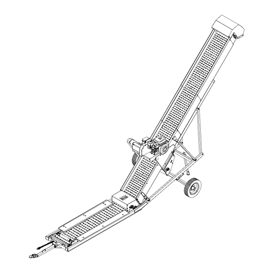
- Page 1 Field Loader OWNER’S MANUAL #03240900 (02-01)
-
Page 2: Table Of Contents
Unless otherwise expressly agreed to by CrustBuster/Speed King,Inc., the consumer shall bear the expense of installation. CrustBuster/Speed King, Inc. will not be liable for consequential damages where the loss is commercial, including but not limited to loss of profit, delays or expenses. -
Page 3: Operator Qualifications / Sign Off Sheet
Operator Qualifications Operation of this conveyor shall be limited to competent and experienced persons. In addition, anyone who will operate or work around conveyor must use good common sense. In order to be qualified, he or she must also know and meet all other requirements, such as: Some regulations specify that no one under the age of 16 may operate power machinery. -
Page 4: Safety Instructions
BE ALERT! Your Safety is involved. General Safety Statement WATCH FOR THIS SYMBOL. IT POINTS OUT IMPORTANT SAFETY ) ) ) ) )) PRECAUTIONS. IT MEANS "ATTENTION BECOME ALERT!" YOUR SAFETY IS INVOLVED. It is your responsibility as an owner, operator, or supervisor to know and instruct everyone using this conveyor at the time of initial assignment and at least annually thereafter, of the proper operation, precautions, and work hazards which exist in the operation of this conveyor in accordance with OSHA Regulations. - Page 5 Shut off power to adjust, service, or clean the conveyor. Keep hands, feet, and clothing away from moving parts. It is a good idea to remove all jewelry before starting the operation. Visually inspect the conveyor periodically during operation for signs of excessive vibration, loose fasteners, and unusual noises.
-
Page 6: Assembly
Assembly The conveyor has been pre-assembled into two main assemblies to simplify final assembly. As with any large machinery, assembly safety is the first concern. Choose a clear, solid, level work area that is large enough to provide room for forklifts and cranes to move easily. Any slings, chains, or stands used to lift or support should be of adequate capacity and in good condition. - Page 7 Assembly STEP #2. Refer to Figure #2. Position spout (2) over the head roller frame on the 15' incline assembly (1) and attach with 6-5/16" x 1" HHCS (3), lock washers (4), and hex nuts (5). Sling and lift the 15' incline assembly (1) up to the end of the main assembly (6).
-
Page 8: Belt
Assembly STEP #3. Refer to Figure #3. To install conveyor belt, insert a shaft through center of belt roll and support it at the hitch end of the conveyor with stands or forklift. Position the belt roll so the pattern is up as the belt is unrolled. Lift the pan sideboards off and place out of the way. -
Page 9: Gas Engine
Assembly and hex nuts (6). Install ground cable to the engine mounting bolt closest to the battery box. Install the 2- B-48 v-belts (13) from the engine sheave to the jack shaft sheave. Move 12" diameter sheave on jack shaft to align with engine sheave. Tighten v-belts using the engine slide take-up bolt. -
Page 10: Electric Motor
Assembly NOTE: 7.5 HP motor required for normal application. Figure #4a ELECTRIC MOTOR STEP #4a. Refer to Figure #4a. Mount the motor slide (1) to the four slotted holes in the drive plate (2) using 4-3/8" x 1" HHCS (3), flat washers (4), lock washers (5), and hex nuts (6). -
Page 11: Guard
Assembly Figure #5 GUARD STEP #5. Refer to Figure #5. Remove end plate (3) from guard assembly (2). Slide guard assembly (2) over jack shaft and engine clutch or motor sheave as shown until hole in bottom tab of guard (2) aligns with slot in side of drive plate (1). -
Page 12: Before Operation
Before Operation 1. GAS: Check engine fluids according to engine 4. To align or train conveyor belt, move belt slowly m a n u f a c t u r e r ’ s o w n e r ’ s m a n u a l one or two complete revolutions. -
Page 13: Transporting
Transporting 1. Check general condition of conveyor for loose 4. Lift conveyor and attach to vehicle towing ball. parts or damage. Check and re-tighten Use proper ball size. Make certain ball is wheel lug nuts. Check tires for proper completely engaged in coupler socket and inflation pressure. -
Page 14: Repair Parts
Undercarriage & Hitch Repair Parts... - Page 15 Undercarriage & Hitch Repair Parts Stainless Steel Mild Steel Item Qty Part No. Description 81884900 Undercarriage 335125 HHCS 3/4" x 2" 156661 Bushing 1 1/8" x 5/8" 433938 Safety Chain 11000# 330233 HHCS 3/4" x 4 ½" 330456 Klik Pin 7/16" 331215 Clevis Pin 3/4"...
-
Page 16: Pan & Transition
Pan & Transition Repair Parts... - Page 17 Pan & Transition Repair Parts Stainless Steel Mild Steel Item Qty Part No. Description Item Qty Part No. Description 81888000 Hold Down Transition 82066200 Hold Down Transition 81623100 Lagged Roller 3½" x 24" 81623100 Lagged Roller 3½" x 24" 03018900 Bearing 1 5/16" 2B Flange 03018900 Bearing 1 5/16"...
-
Page 18: Drive
Drive Repair Parts... - Page 19 Drive Repair Parts Stainless Steel Mild Steel Item Qty Part No. Description Item Qty Part No. Description 18907600 Drive Mount Plate Left 17158700 Drive Mount Plate Left 12639100 Drive Mount Strap 17160300 Drive Mount Strap 05316500 Decal Turn Fuel Off 05316500 Decal Turn Fuel Off 06874200 Roller Clip 1/16"...
-
Page 20: Gas Drive
Gas Drive Repair Parts Belt Guard Bracket Locations... - Page 21 Gas Drive Repair Parts Stainless Steel Mild Steel Item Qty Part No. Description Item Qty Part No. Description 17148800 Guard Front Plate MS 17104100 Guard Front Plate SS 17150400 Guard Side Plate MS 16564700 Guard Side Plate SS 17188400 Guard End Plate MS 16604100 Guard End Plate SS 01150200 HHCS 1/4"...
-
Page 22: Electric Drive
Electric Drive Repair Parts Belt Guard Bracket Locations... - Page 23 Electric Drive Repair Parts Stainless Steel Mild Steel Item Qty Part No. Description Item Qty Part No. Description 17104100 Guard Front Plate SS 17148800 Guard Front Plate MS 16564700 Guard Side Plate SS 17150400 Guard Side Plate MS 16604100 Guard End Plate SS 17188400 Guard End Plate MS 01245000 HHCS 1/4"...
-
Page 24: Pan
Repair Parts... -
Page 25: Spout
03934700 Nylock 3/8" SS 330035 Hex Nut 3/8" 01134600 HHCS 3/8" x 1" SS 01017300 HHCS 3/8" x 1" 01114800 Decal Speed King 01114800 Decal Speed King 83932400 Pan 10' x 24" 82050600 Pan 10' x 24" 02219400 Flat Washer 3/8" SS 330894 Flat Washer 3/8"... -
Page 26: 3' Extension
3' Extension Repair Parts... - Page 27 3' Extension Repair Parts Stainless Steel Mild Steel Item Qty Part No. Description Item Qty Part No. Description 61154100 Pan Assembly 3' x 24" SS 62583000 Pan Assembly 3' x 24" MS 18916700 Truss Support 18916700 Truss Support 17622200 Splice Plate 17623000 Splice Plate 81262800 Truss Rod 7' 81262800 Truss Rod 7'...
- Page 28 P.O.Box 1438 Dodge City, Kansas 67801 (620) 227-7106...
Need help?
Do you have a question about the Speed King and is the answer not in the manual?
Questions and answers