Table of Contents
Advertisement
Quick Links
Advertisement
Table of Contents

Related Manuals for CrustBuster 3200


Summary of Contents for CrustBuster 3200
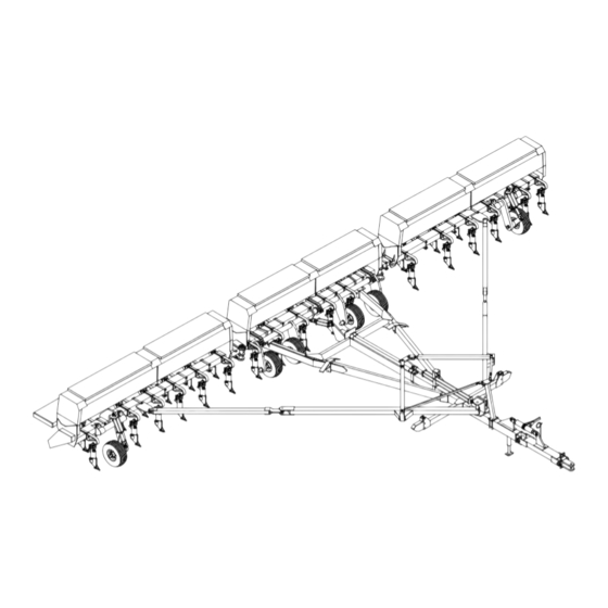
- Page 1 3200 Trash Shank OWNER'S MANUAL (01-10) # 601401...
- Page 2 WARRANTY: In addition to the implied warranties of fitness and of merchantability, CrustBuster®/Speed King, Inc. warrants new products sold by it to be free from defects in workmanship and material for a period of 12 months, from the date of delivery to the first user customer.
-
Page 3: Table Of Contents
Table of Contents Introduction Repair Parts Identification & Warranty ..Inside Cover 32' A-Frame ....32-33 Safety . - Page 4 If special attention is required for some tenance to keep it in top running condition. condition, ask your CrustBuster dealer; he We have attempted to cover all the adjust- will be glad to help and answer any questions ments required to fit most conditions;...
-
Page 5: Safety
Safety RECOGNIZE SAFETY INFORMATION UNDERSTAND SIGNAL WORDS FOLLOW SAFETY INSTRUCTIONS... - Page 6 Safety OPERATE SAFELY AVOID TIP-OVERS KEEP RIDERS OFF MACHINE...
- Page 7 Safety HANDLE FUEL SAFELY - AVOID FIRES PREPARE FOR EMERGENCIES WEAR PROTECTIVE CLOTHING...
- Page 8 Safety USE SAFETY LIGHTS AND DEVICES TRANSPORT SAFELY...
- Page 9 Safety TOW LOADS SAFELY PRACTICE SAFE MAINTENANCE...
- Page 10 Safety AVOID HIGH-PRESSURE FLUIDS CHARGE ROW MARKER HYDRAULIC SYSTEM...
-
Page 11: Operating Cautions
Lower drill while moving forward to avoid plugging. Check seed depth and adjust accordingly. Allow no riders. The CrustBuster 3200 Trash Shank Drill ..is built for the aggressive farmer who needs . . . boxes feature a one-point adjustable seed... - Page 12 Assembly Instructions 32' Drill The main and wing sections are pre-assembled at the factory to simplify final assembly. Extreme caution should be taken during assembly for safety. Use sturdy stands in the proper places and use dependable lifting devices for heavy parts. Lay out parts in an area which allows enough room for crane, winch truck, or other safe lifting device to assemble drill.
-
Page 13: Assembly Instructions 32' Drill
Assembly Instructions 32' Drill STEP 7 (Refer to Figure 7) Install hitch on front of A-frame (lug on STEP 9 (Refer to Figure 9) hitch goes on top, pointing to back of drill) Front pull bars are installed between plates with 1 1/2"... - Page 14 Assembly Instructions 32' Drill STEP 11 (Refer to Figure 11) STEP 14 Install a 2" x 8" hydraulic cylinder (base Attach pull bar truss stand to A-frame in end to frame -- ram end to wheel lug -- front of fold lug with two (2) 3/4" x ports to inside of drill) to wing wheel 4"...
- Page 15 Assembly Instructions 32' Drill Figure 15 Item Qty Part No. Description 466912 Adpt Straight 3/4" MOR x ½" NPTF 464057 Adpt Straight 3/4" MOR x 3/8" NPTF Sw 463513 Adpt 90E ½" NPTM x 3/8" NPTF Sw w/Restrictor 463539 Adpt 90E ½" NPTM x 3/8" NPTF Sw 466763 Adpt 90E 3/4"...
-
Page 16: 40' Drill
Assembly Instructions 32' Drill STEP 17 FOLD ADJUSTMENTS. Install cylinder STEP 4 Install one hose carrier to tab on back lockout in center frame cylinder and se- center stub of A-frame with 1/2" x 1 1/2" cure with 5/16" x 2 3/4" pin. Switch selec- HHCS, lock washer, and hex nut. - Page 17 Assembly Instructions 40' Drill STEP 7 (Refer to Figure 7) STEP 9 (Refer to Figure 9) Install hitch on front of A-frame (lug on Install front pull bar swivels into holes in front of A-frame. Secure with 1" x 4 1/2" hitch goes on top, pointing to back of drill) HHCS, 1/4"...
- Page 18 Assembly Instructions 40' Drill STEP 11 Attach pull bar slides to each side of A- STEP 15 FOLD ADJUSTMENTS. Install cylinder frame in front of cross tube with lockout in center frame cylinder and se- 1/2" x 4 1/2" HHCS, lock washer, and hex cure with 5/16"...
- Page 19 Assembly Instructions 40' Drill Figure 13 Item Qty Part No. Description 466912 Adpt Straight 3/4" MOR x ½" NPTF 464057 Adpt Straight 3/4" MOR x 3/8" NPTF Sw 463513 Adpt 90E ½" NPTM x 3/8" NPTF Sw w/Restrictor 463539 Adpt 90E ½" NPTM x 3/8" NPTF Sw 466763 Adpt 90E 3/4"...
-
Page 20: Maintenance
Maintenance 1. Preventative maintenance is the key to the 4. At the end of each season, clean the feed slot long life of any farm implement. With careful with diesel fuel. This will provide a protective and systematic inspection of your grain drill, coating against rust and corrosion. -
Page 21: Transporting
Transporting Instructions To hook clevis to tractor, adjust hitch up or down ment on both sides extending beyond the end of using hitch jack. Insert the hitch pin or large bolt the center box when unit is folded. A large part (Grade 8 or more) with locking nut. - Page 22 Operating Instructions Field Operation. . . (cont'd) CAUTION: Before filling grain boxes, properly hitch the drill to tractor to pre- Disconnect all wing carrier latch plates. (Failure vent possibility of drill tipping over back- to do so will cause damage to frame and folding ward.
-
Page 23: Wobble Slot Seed Cup
Wobble Slot Seed Cup Adjustments and Service The wobble slot seed cups should be checked against fortably and give solid contact against each half. It may the slot gauge initially and anytime service has been be necessary to turn the hex shaft slightly to position the performed on the seed shaft or individual seed cups. - Page 24 Wobble Slot Seed Cup Adjustments and Service For round seeds, the ideal slot width can be 3. Place a mark on the press wheel and lower the determined by measuring seed size. To attain drill into the ground. Pull the drill through the singular file flow of seeds from the wobble slot seed field and count the number of revolutions the cup, the slot width should be greater than one and...
-
Page 25: Standard Presswheel Setting
Standard Presswheel Setting CAUTION: More down pressure will raise drill out of ground as box empties. With adjustment clamp all the way up, set your planting depth. Move clamp down to within 1/4" of presswheel spring after depth is set. Sprocket Locations... -
Page 26: Seed Rate Charts
Seed Rate Charts ALFALFA SEEDING RATES (POUNDS PER ACRE) Seeding Rate SPROCKETS 10" Spacing 12" Spacing c c c c " Slot c c c c " Slot ¼" Slot Slot ¼" Slot Slot 2½ 2½ 4½ 7½ 4½ 7½ 7½... - Page 27 Seed Rate Charts CANOLA SEEDING RATES (POUNDS PER ACRE) Seeding Rate (8-22-13) SPROCKETS 10" Spacing 12" Spacing d d d d " Slot d d d d " Slot " Slot ¼" Slot " Slot ¼" Slot CORN SEEDING RATES (POUNDS PER ACRE) Seeding Rate SPROCKETS 10"...
- Page 28 Seed Rate Charts COTTON SEEDING RATES (POUNDS PER ACRE) Seeding Rate SPROCKETS 10" Spacing 12" Spacing e e e e " Slot e e e e " Slot ½" Slot ¾" Slot ½" Slot ¾" Slot 12½ 12½ 17½ 17½ 22½...
- Page 29 Seed Rate Charts MILLET SEEDING RATES (POUNDS PER ACRE) Seeding Rate SPROCKETS 10" Spacing 12" Spacing c c c c " Slot c c c c " Slot ¼" Slot Slot ¼" Slot Slot 2½ 2½ 4½ 7½ 4½ 7½ 17½...
- Page 30 Seed Rate Charts OATS SEEDING RATES (POUNDS PER ACRE) Seeding Rate SPROCKETS 10" Spacing 12" Spacing e e e e " Slot e e e e " Slot ½" Slot ¾" Slot ½" Slot ¾" Slot 12½ 7½ 12½ 12½ 12½...
- Page 31 Seed Rate Charts RICE SEEDING RATES (POUNDS PER ACRE) Seeding Rate SPROCKETS 10" Spacing 12" Spacing e e e e " Slot e e e e " Slot ½" Slot ¾" Slot ½" Slot ¾" Slot 12½ 17½ 12½ 17½ 17½...
- Page 32 Seed Rate Charts SOYBEANS SEEDING RATES (POUNDS PER ACRE) SPROCKETS 10" Spacing 12" Spacing e e e e " Slot e e e e " Slot ½" Slot ¾" Slot ½" Slot ¾" Slot 12½ 12½ 17½ 17½ 17½ 37½ 22½...
-
Page 33: Plant Population Chart
Seed Rate Charts WHEAT SEEDING RATES (POUNDS PER ACRE) Seeding Rate SPROCKETS 10" Spacing 12" Spacing e e e e " Slot e e e e " Slot ½" Slot ¾" Slot ½" Slot ¾" Slot 27½ 27½ 32½ 17½ 22½... -
Page 34: 32' A-Frame
32' A-Frame... - Page 35 32' A-Frame Item Part No. Description Item Part No. Description 958868 32' A-Frame 953026 Pull Bar Pin 331405 U-bolt 3/4" x 4" x 7 1/2" 959072 Fold Arm Pin 959445 Pull Bar Truss Stand 959692 Pull Bar Slide 959486 Pull Bar Truss Swivel 151118 Bushing 959452...
-
Page 36: 40' A-Frame
40' A-Frame... - Page 37 40' A-Frame Item Part No. Description Item Part No. Description 958777 40' A-Frame 01147800 HHCS 1/2" x 1 1/2" 959585 Pull Bar Swivel 330100 HHCS 1/2" x 4 1/2" 959577 Pull Bar Front 334870 HHCS 1" x 4" 959593 Pull Bar Rear 330597 Hex Nylock 1"...
-
Page 38: Frame Sections 32' & 40' Center
Center Frame Section... - Page 39 Center Frame Section Item Part No. Description Item Part No. Description 802736 Mounted Tire Assembly 330282 HHCS 3/4" x 7" INCLUDES: 335125 HHCS 3/4" x 2" 530154 Tire 9.5L x 15 333575 Hex Nut 1 1/2" 530162 Wheel 6 Bolt 15 x 8 w/ 5/16"...
-
Page 40: 32' Left Wing
32' Left Wing Section... - Page 41 32' Left Wing Section Item Part No. Description Item Part No. Description 807313 Mounted Tire Assembly 843193 Front Row Tooth Assembly INCLUDES: w/Point/Hard Surfaced Shoe 530154 Tire 9.5L x 15 959304 Front Row Tooth Clamp 4 x 6 530238 Wheel 5 Bolt 15 x 6 334458 HHCS ½"...
- Page 42 32' Right Wing Section...
-
Page 43: 32' Right Wing
32' Right Wing Section Item Part No. Description Item Part No. Description 807313 Mounted Tire Assembly 333575 Hex Jam Nut 1 1/2" INCLUDES: w/ 5/16" Set Screw 530154 Tire 9.5L x 15 843193 Front Row Tooth Assembly 530238 Wheel 5 Bolt 15 x 6 w/Point/Hard Surfaced Shoe 530287 Valve Stem... -
Page 44: 40' Left Wing
40' Left Wing Section... - Page 45 40' Left Wing Section Item Part No. Description Item Part No. Description 807313 Mounted Tire Assembly 843193 Front Row Tooth Assembly INCLUDES: w/Point/Hard Surfaced Shoe 530154 Tire 9.5L x 15 959304 Front Row Tooth Clamp 4 x 6 530238 Wheel 5 Bolt 15 x 6 334458 HHCS 1/2"...
- Page 46 40' Right Wing Section...
-
Page 47: 40' Right Wing
40' Right Wing Section Item Part No. Description Item Part No. Description 807313 Mounted Tire Assembly 333575 Hex Jam Nut 1 1/2" INCLUDES: w/ 5/16" Set Screw 530154 Tire 9.5L x 15 843193 Front Row Tooth Assembly 530238 Wheel 5 Bolt 15 x 6 w/Point/Hard Surfaced Shoe 530287 Valve Stem... -
Page 48: Center
Center Drive Assembly... - Page 49 Center Drive Assembly Item Part No. Description Item Part No. Description 330928 Klik Pin 3/16" 432930 Chain #32 x 37 Links 331694 Machine Bushing 918714 Chain Guard Flange 1 1/4" x 3/4" x 10 ga 250860 Right Chain Guard Plate 500330 Spring 250829...
-
Page 50: Left
Left Drive Assembly... - Page 51 Left Drive Assembly Item Part No. Description Item Part No. Description 330928 Klik Pin 3/16" 432930 Chain #32 x 37 Links 331694 Machine Bushing 918714 Chain Guard Flange 1 1/4" x 3/4" x 10 ga 250860 Right Chain Guard Plate 500330 Spring 250829...
-
Page 52: Right
Right Drive Assembly... - Page 53 Right Drive Assembly Item Part No. Description Item Part No. Description 330928 Klik Pin 3/16" 302802 Hex Shaft 5/8" x 31 1/8" 331694 Machine Bushing 432930 Chain #32 x 37 Links 1 1/4" x 3/4" x 10 ga 918714 Chain Guard Flange 500330 Spring 250860...
-
Page 54: Box Assembly
Box Assembly... - Page 55 Box Assembly Item Part No. Description Item Part No. Description Box Assemblies 221317 Latch Handle 876433 126" x 10" Center 01011600 HHCS 5/16" x 1 1/4" 876474 126" x 10" Left Wing 335703 HHCS 3/8" x 1½" 876458 126" x 10" Right Wing 149385 Box Lid Bushing 876441...
-
Page 56: Hitch
Hitch Item Part No. Description 936476 Clevis Hitch 306118 Hitch Pin 02450500 HHCS 5/16" x 3" 331611 Hex Nylock Nut 935700 Hitch Weldment 935924 Hose Carrier 331926 HHCS 1/2" x 2" 330142 Lock Washer 1/2" 330134 Hex Nut 1/2" 605899 Ratchet Turnbuckle Assembly...
Need help?
Do you have a question about the 3200 and is the answer not in the manual?
Questions and answers