Table of Contents
Advertisement
Advertisement
Table of Contents

Subscribe to Our Youtube Channel
Related Manuals for CrustBuster 4000 Series


Summary of Contents for CrustBuster 4000 Series
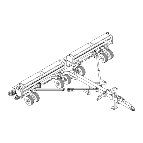
- Page 1 4000 SERIES ALL PLANT & MIN-TILL DRILL OWNER'S MANUAL (4-01) #604694...
- Page 2 WARRANTY PROCEDURE: Should any part fail to conform with this warranty, CrustBuster®/Speed King, Inc. will repair or replace the part or parts which do not conform. If a part is defective, take it to your authorized CrustBuster® Farm Equipment Dealer immediately, along with your warranty registration, and complete the proper forms requesting a warranty adjustment.
-
Page 3: Table Of Contents
Table of Contents Introduction Repair Parts - Cont. Identification & Warranty ..Inside Cover Opener Assemblies & Blades Safety ....... . 2-8 All Plant Opener . - Page 4 If special attention is required for some tenance to keep it in top running condition. condition, ask your CrustBuster dealer; he We have attempted to cover all the adjust- will be glad to help and answer any questions ments required to fit most conditions;...
-
Page 5: Safety
Safety... - Page 6 Safety...
- Page 7 Safety...
- Page 8 Safety...
- Page 9 Safety...
- Page 10 Safety...
-
Page 11: Operating Cautions
Before Operating This Equipment Read and understand this owner's manual. Secure implement to tractor drawbar with as large a hitch pin as allowed. A large bolt with locking nut or castle nut is recommended. Do not use a hairpin or wire to secure hitch pin. -
Page 12: Lubrication, Maintenance, And Service
Lubrication, Maintenance, and Service Lubrication and Maintenance Proper maintenance will extend the life of your drill and give you years of excellent performance. Refer to the illustrations below for lubrication requirements. Use a high quality grease in pivot points and bearings. On greaseable sealed bearings, be careful not to over- grease and destroy the dirt seal. -
Page 13: Transporting
Clutch Maintenance CAUTION! At the start of a new drilling season, or anytime the drill is going to be used, especially if the drill has been stored out in the weather all winter long, make sure the clutch drive is not frozen up. Failure to do this will result in damage to the clutch assembly. -
Page 14: Wobble Slot Seed Cup Adjustments
Wobble Slot Seed Cup Adjustments and Service The wobble slot seed cups should be checked against gauge to equal the slot width you have just measured the slot gauge initially and anytime service has been with the keystock by loosening with a screwdriver and performed on the seed shaft or individual seed cups. -
Page 15: Meter Man Acreage Counter
To attain singular file flow of listed when using CrustBuster drills. seeds from the wobble slot seed cup, the slot width should be greater than one and one half (1 ½) times the... -
Page 16: Field Operation
Field Operation Recommended Operating Speed Blade Gap Adjustment - (cont'd.) Operating speeds of 4-7 mph will provide optimum the gap between blades will increase. Removing each results from your Min-Till and All Plant drill. Conven- blade from the opener bracket allows the operator to tional field conditions can warrant speeds in the take shim washers from behind the bearing and re- upper end of the range. -
Page 17: All Plant Settings
If you have purchased a Min-Till Drill, the operation procedures continue on page 18. All Plant Drill TOOL BAR LIFT CYLINDER SET Opener / Tool Bar Adjustments AT RECOMMENDED SETTING. The All Plant units are attached to a 4x4 bar that is rotated by two cylinders on each section of the drill. - Page 18 All Plant Drill Setting Down Pressure Down Pressure Spring The parallel linkage opener design assures the opera- Replacement tor the opener blades and presswheel operate on the (Refer to drawing on page 17 in Conventional Field same level throughout the range of up and down travel. Conditions section.) Due to the location of the down pressure spring, the If a down pressure spring breaks, the remaining portion...
- Page 19 All Plant Drill Setting Seed Depth - Conventional Field Conditions (cont.) For tilled field conditions, the lightest spring setting (top notch) is recommended. More weight will be trans- DEEP ferred to the carrying wheels of the drill when the toolbar is rotated. Behind tractor and drill tires it may be necessary to adjust individual row units for extra down pressure or different depth setting.
-
Page 20: Min Till Settings
Min-Till Drill Setting Down Pressure Opener pressure setting is easy and allows separate settings for tire compaction areas to different soil conditions from field to field. Ratchet mechanism allows you to turn the pressure up or down. The locking key rolls up or down the notch gauge and locks to your desired setting from 140# to 250# per opener. - Page 21 Min-Till Opener Presswheel Adjustment with Tool Bar Rotation F TOOL BAR LIFT CYLINDER SET AT RECOMMENDED SETTING. CYLINDER RETRACTED WITH DEPTH SCREW STOP TURNED OUT 1". THIS MAKES CYLINDER LENGTH FROM PIN HOLE TO PIN HOLE 21¼" AS SHOWN. F ROTATE TOOL BAR INTO THE GROUND.
-
Page 22: Calibration And Drilling Rates
One method involves catching seed from one or more seed cups and utilizing a density scale to determine actual rates. These scales are commercially available, inexpensive and very easy to use. Information can be obtained from CrustBuster®/Speed King, Inc. -
Page 23: Sprocket Locations
4000 Sprocket Locations... -
Page 24: Seed Rate Charts
Seed Rate Charts ALFALFA BARLEY Sprockets Slot Width Sprockets Slot Width Derailleur Box End Pounds/Acre Derailleur Box End Pounds/Acre H 1/8" 1/4" H 1/2" 5/8" 3/4"... - Page 25 Seed Rate Charts CANOLA CORN Sprockets Slot Width Sprockets Slot Width Derailleur Box End Pounds/Acre Derailleur Box End Pounds/Acre H 3/16" 1/4" 3/8" H 1/2" 5/8" 3/4"...
- Page 26 Seed Rate Charts COTTON FESCUE Sprockets Slot Width Sprockets Slot Width Derailleur Box End Pounds/Acre Derailleur Box End Pounds/Acre H 1/2" 5/8" 3/4" H 3/8" 1/2" 5/8"...
- Page 27 Seed Rate Charts MILLET MILO Sprockets Slot Width Sprockets Slot Width Derailleur Box End Pounds/Acre Derailleur Box End Pounds/Acre H 3/16" 1/4" 3/8" H 3/16" 1/4" 3/8"...
- Page 28 Seed Rate Charts OATS PINTO BEANS Sprockets Slot Width Sprockets Slot Width Derailleur Box End Pounds/Acre Derailleur Box End Pounds/Acre H 1/2" 5/8" 3/4" 1/2" 5/8" 3/4" 84 101 89 107 94 112 75 100 99 118 79 105 78 104 124 82 110 82 109 130 86 115...
- Page 29 Seed Rate Charts RICE Sprockets Slot Width Sprockets Slot Width Derailleur Box End Pounds/Acre Derailleur Box End Pounds/Acre H 1/2" 5/8" 3/4" 1/2" 5/8" 3/4" 78 100 82 106 87 112 90 105 92 117 95 110 96 123 99 115 78 101 129 83 104 120 82 105 135...
- Page 30 Seed Rate Charts SOYBEANS SUNFLOWERS Sprockets Slot Width Sprockets Slot Width Derailleur Box End Pounds/Acre Derailleur Box End Pounds/Acre H 3/8" 1/2" 5/8" 3/4" H 1/2" 5/8" 3/4" 82 102 87 107 91 113 96 119 75 100 124 79 105 130 77 103 128 82 109 136 87 116 144...
- Page 31 Seed Rate Charts WHEAT Sprockets Slot Width Derailleur Box End Pounds/Acre H 1/2" 5/8" 3/4" 85 102 90 108 95 114 80 100 120 84 105 126 88 110 132 92 115 138 92 115 138 98 122 147 25 104 130 156 25 109 137 164 25 115 144 173 25 121 151 182...
-
Page 32: Hitch
4000 Hitch Item Part No. Description Item Part No. Description 954529 Mono Clevis (Option) 01010800 HHCS 5/16" x 1" 954230 Clevis 330845 Lock Washer 5/16" 331579 HHCS 3/4" x 7 1/2" 330811 Hex Nut 5/16" 330316 Hex Nylock Nut 3/4" 604587 Rubber Grommet 2"... -
Page 33: Tongue
4000 Tongue Item Part No. Description Item Part No. Description 954305 Jack Stand 861476 Cover Cap Assembly 330449 Clevis Pin 330407 Lock Washer 1" 330456 Klick Pin 7/16" 330837 Hex Nylock Nut 3/8" 958074 Wing Carrier Weldment 308791 Tongue Pin 334987 HHCS 1"... -
Page 34: Wing Sections 4025 / 4030
4025 & 4030 Left Wing Sections 4030 Left Wing Section 4025 Left Wing Section Item Part No. Description Item Part No. Description 958157 4030 Left Wing Frame 860726 Clutch Assy w/Hub /No Bolts 958207 4025 Left Wing Frame 07949100 Disc Torque Limiter 308817 Hinge Pin 954313... - Page 35 4025 & 4030 Right Wing Sections 4030 Right Wing Section 4025 Right Wing Section Item Part No. Description Item Part No. Description 958165 4030 Right Wing Frame 860726 Clutch Assy w/Hub/No Bolts 958215 4025 Right Wing Frame 07949100 Disc Torque Limiter 308817 Hinge Pin 954313...
-
Page 36: Tool Bars 4025 / 4030 All Plant
4025 All Plant Tool Bar Item Part No. Description 953919 Tool Bar Right 953901 Tool Bar Left 337196 Tool Bar Hanger Bolt 330597 Nut 1" Hex Nylock 08993800 Roll Pin 1/4" x 2" 336057 Roll Pin 1/4" x 1 1/2" 330407 Flat Washer 1"... -
Page 37: 4020 All Plant
4020 All Plant Tool Bar Item Part No. Description 954909 Tool Bar Right (7½“ & 8") 956284 Tool Bar Right (7½“, 8", &10" wide spacing) 954891 Tool Bar Left (7½" & 8") 956276 Tool Bar Left (7½“, 8", &10" wide spacing) 337196 Tool Bar Hanger Bolt 330597... -
Page 38: 4025 / 4030 Min Till
4025 Min-Till Tool Bar Item Part No. Description 957514 Tool Bar Right 957456 Tool Bar Left 337196 Tool Bar Hanger Bolt 330597 Nut 1" Hex Nylock 08993800 Roll Pin 1/4" x 2" 336057 Roll Pin 1/4" x 1 1/2" 330407 Flat Washer 1"... -
Page 39: Slide Fold & Pull Bar
4020, 4025, & 4030 Slide Fold & Pull Bar Item Part No. Description 954263 Inner Swing Arm Right 954271 Inner Swing Arm Left 954818 Pull Bar Front Right (20') 954826 Pull Bar Front Left (20') 465286 Cylinder 5 x 20 464412 Seal Kit for 5 x 20 Cylindr 334243... - Page 40 4025 & 4030 Grain Box (2.5 Bu/Ft)
- Page 41 4025 & 4030 Grain Box Item Part No. Description Item Part No. Description 958397 Walkboard 4025 * 43 Box Bottom Assemblies (Cont'd) 957290 Walkboard 4030 865972 4025 Left 8" Spacing 216192 Box End Walkboard Bracket Rt 865964 4025 Right 8" Spacing (Shown) 866863 4025 Left...
- Page 42 4020 Grain Box (2.5 Bu/Ft)
- Page 43 4020 Grain Box Item Part No. Description Item Part No. Description 955187 Box Bottom 7½" Spacing 334557 Machine Screw #8 x 1/4" Rd Hd 955195 Box Bottom 8" Spacing 334516 Set Screw 1/4-28 x 1/4 Cone Pt 955203 Box Bottom 10"...
-
Page 44: Drives 4025 / 4030
4025 & 4030 Left Drive Item Part No. Description Item Part No. Description 860726 Clutch Assembly w/Hub 860825 Throw-out Clutch Half Assy 07949100 Disc Torque Limiter 501031 Spring 954313 Clutch Pressure Plate 06409700 Set Collar 1" 954370 Hub Drive Sprocket 2050 18T 330126 HHCS 1/2"... - Page 45 4025 & 4030 Right Drive Item Part No. Description Item Part No. Description 860726 Clutch Assembly w/Hub 860825 Throw-out Clutch Half Assy 07949100 Disc Torque Limiter 501031 Spring 954313 Clutch Pressure Plate 06409700 Set Collar 1" 954370 Hub Drive Sprocket 2050 18T 330126 HHCS 1/2"...
- Page 46 4020 Wing Sections. Drive, & Grain Box...
- Page 47 4020 Wing Sections, Drive Assembly, and Grain Box Item Part No. Description Item Part No. Description 865576 Mounted Tire 11L 10 Ply 6B 309062 Sprocket Adapter 953299 Wing Wheel Spindle 602367 Key 1/4" x 1/4" x 1" 310656 Key 3/16" x 1 1/2" 305425 Chain Guard Hinge Pin 400739...
- Page 48 4025 & 4030 Gear Box Left...
-
Page 49: Gear Boxes
4025 & 4030 Gear Box Left Item Part No. Description Item Part No. Description 309088 Handle Shaft 309104 Adjustment Handle Shaft 604611 Black Plastic Knob 954347 Sprocket Cluster Bracket 332452 Roll Pin 5/32 x 1 1/4 309054 Cluster Shaft 860908 Derailleur Clutch Mount Assy 432708 Sprocket Cluster... - Page 50 4025 & 4030 Gear Box Right...
- Page 51 4025 & 4030 Gear Box Right Item Part No. Description Item Part No. Description 309088 Handle Shaft 309104 Adjustment Handle Shaft 604611 Black Plastic Knob 954347 Sprocket Cluster Bracket 332452 Roll Pin 5/32 x 1 1/4 309054 Cluster Shaft 860908 Derailleur Clutch Mount Assy 432708 Sprocket Cluster...
- Page 52 4020 Gear Box Left...
- Page 53 4020 Gear Box Left Item Part No. Description Item Part No. Description 309088 Handle Shaft 309104 Adjustment Handle Shaft 604611 Black Plastic Knob 954347 Sprocket Cluster Bracket 332452 Roll Pin 5/32 x 1 1/4 309054 Cluster Shaft 860908 Derailleur Clutch Mount Assy 432708 Sprocket Cluster 01010800 HHCS 5/16 x 1...
- Page 54 4020 Gear Box Right...
- Page 55 4020 Gear Box Right Item Part No. Description Item Part No. Description 309088 Handle Shaft 309104 Adjustment Handle Shaft 604611 Black Plastic Knob 954347 Sprocket Cluster Bracket 332452 Roll Pin 5/32 x 1 1/4 309054 Cluster Shaft 860908 Derailleur Clutch Mount Assy 432708 Sprocket Cluster 01010800 HHCS 5/16 x 1...
-
Page 56: All Plant Opener
All Plant Opener Assembly... - Page 57 All Plant Opener Assembly Item Part No. Description Item Part No. Description 859843 Right Short Opener Assembly 954628 Presswheel Swivel Bracket 859850 Left Short Opener Assembly 01158500 HHCS 3/8" x 1 1/4" Gr 5 859868 Right Long Opener Assembly w/Hex Nylock Nut 859876 Left Long Opener Assembly 337063...
-
Page 58: Min Till Opener
Min-Till Opener Assembly... - Page 59 Min-Till Opener Assembly Item Part No. Description Item Part No. Description 864942 Right Short Opener Assembly 150508 Spacer Spool 1 27/64" 864967 Right Long Opener Assembly 216747 Cam Washer Plate 864959 Left Short Opener Assembly 335422 HHCS 1/2" x 2 1/2" Gr 5 864975 Left Long Opener Assembly 331363...
-
Page 60: All Plant Blades
All Plant Opener Blade Assemblies #845917 16" Blade Assembly - Plain Item Part No. Description 501429 Blade 16" OD 4mm Plain 551200 Cast Bearing Flange 603084 Button Head Rivet 5/16" x 5/8" 401042 Bushing 636761 Bearing & Flange Sub-Assy #845925 16"... -
Page 61: Min Till Blades
Min-Till Opener Blade Assemblies #859090 15" Blade Assembly Item Part No. Description 501973 Blade 15" OD x 3MM 401042 Bearing 603084 Rivet 5/16" x 5/8" Button Head 551234 Bearing Flange 636860 Bearing Flange Assembly (Includes Items 2 & 4) #863597 13½"... -
Page 62: Feed Tubes
Feed Tubes 4020 All Plant Item Part No. Description 604777 Clamp 1.375 x .162 (A-22) Upper Seed Tube 571208 Long Opener-19" 571018 Short Opener-18" 863324 Bottom Tube Assembly-18" 570960 Suction Hose 4.5" 570945 Tube 14.5" 603027 Clamp 1.375 x .162 (A-22) 603027 Clamp 1.625 x .172 (A-26) 4025 &... -
Page 63: Clutch Lever Assemblies
Clutch Lever Assemblies 4020, 4020 4025 (Prior 1997) & 4030 #866186 - Left (Shown) #863811 - Left (Shown) #866194 - Right #863829 - Right Item Part No. Description Item Part No. Description 337311 Screw 3/8" x 1 3/4" 337311 Screw 3/8" x 1 3/4" Flat Head Socket Flat Head Socket 958694... -
Page 64: Hub Assemblies
Hub Assemblies 6 Bolt Hub #551291 Item Part No. Description 400861 Grease Seal 400853 Inner Bearing 400846 Inner Cup 550707 6 Bolt Hub w/Cups Only 330464 Lug Bolt 1/2" x 1 3/4" 05742200 Outer Cup 05741400 Outer Bearing 02080000 Spindle Washer 331801 Spindle Nut 02154300 Cotter Pin... -
Page 65: Clutch Assemblies
Clutch Assembly #860726 Item Part No. Description 330464 Wheel Bolt 1/2" x 1 3/4" SAE 331314 Wheel Nut 1/2"-20 90° 551291 Q783 Hub Complete less bolts 954321 Clutch Plate 337139 Tap Bolt 1/2" x 2" SAE Gr 5 502039 Spring 1 1/4" x 1/2" x 2 1/4" 334110 Nut 1/2"... - Page 66 Clutch Half & Drive Clutch Assembly to Gear Box 5/16" roll pin is used to hold drive clutch sprocket assembly in place. CAUTION! Be sure throw-out clutch half assembly moves forward and back easily. WARNING! When you re-adjust clutch lever, make sure spring does not totally collapse.
- Page 67 All Plant Presswheel Arm Assemblies #859991 2" x 13" Peaked w/Smooth Sides Item Part No. Description 01572700 Hex Nylock Nut 5/8" 530667 Presswheel 2 x 13 Peaked w/Smooth Sides 954636 Presswheel Arm 337873 HHCS 1/2" x 5½" Gr8 331983 HHCS 5/8" x 4" 148999 Bushing .747 x .532 x 3.594 331363...
-
Page 68: Presswheel Assemblies
Presswheel Assemblies #852368 3" x 13" Center Rib Item Part No. Description 334573 HHCS 5/16" x 2 3/4" Gr 5 331611 Nut 5/16" Hex Nylock 401042 Bearing 530642 Presswheel 3" x 13" Center Rib 951962 3" x 13" Presswheel Half w/Ring 951970 3"... - Page 69 Presswheel Assemblies #530667 (Hammer) 2" x 13" Peaked w/Smooth Sides Item Part No. Description HHCS 3/8" x 1 5/8" Gr 5 HHCS 3/8" x 5/8" Gr5 530758 2x13 Smooth Presswheel Side 530766 2x13 Peaked Presswheel 401042 Bearing Hex Locknut 3/8" #530717 (Hammer) 2"...
-
Page 70: Hydraulic Cylinders
Hydraulic Cylinders 3" x 20" Hyd. Cylinder 4" x 10" Hyd. Cylinder 1 1/4" Ram w/ 3/4-16 SAE Ports 1 1/2" Ram w/ 3/4-16 SAE Ports CBI No. 468173 CBI No. 468421 Item CBI No. Description Item CBI No. Description Shipped Less Clevis 461483 Clevis... - Page 71 Hydraulic Cylinders 3" x 8" Hyd. Cylinder w/Depth Control 3 1/2" x 8" Hyd. Cylinder w/Depth Control 1 1/4" Ram w/ 3/4-16 SAE Ports 90° to Pins 1 1/2" Ram w/ 3/4-16 SAE Ports CBI No. 469924 CBI No. 468413 Item CBI No.
- Page 72 4025 & 4030 Marker Mounting & Assembly Instructions Remove contents of hardware box and sort Remove the cylinder port plugs and extend according to packing sheet for parts identification. hydraulic cylinder rams out to align cylinder Refer drawing lay-out. Using brackets with slotted holes in ladder sections and 3/4"...
- Page 73 4025 & 4030 Hydraulic Marker Item Part No. Description 334987 HHCS 1" x 3" 330407 Flat Washer 1" 330399 Lock Washer 1" 330381 Hex Nut 1" 01172600 HHCS 1" x 2 1/2" 330381 Hex Nut 1" 938399 Marker Base Mt Bracket Right 938407 Marker Base Mt Bracket Left 335174...
-
Page 74: Tri-Fold
4000 Tri-Fold Marker... - Page 75 4000 Tri-Fold Marker Item Part No. Description Item Part No. Description 334987 HHCS 1" x 3" 334946 HHCS 1/2" x 3" 330407 Flat Washer 1" 330134 Hex Nut 1/2" 330399 Lock Washer 1" 330142 Lock Washer 1/2" 330381 Hex Nut 1" 954685 Adjustable Marker Arm 01172600 HHCS 1"...
- Page 76 Tri-Fold Marker Mounting & Assembly Instructions Remove contents of hardware box and sort parts On the marker base arms --right and left, install for identification. Refer to drawing lay-out. Using marker adjustment chain pins using 5/32" hair the 3/4" x 7" x 11" U-bolts, 3/4" lock washers and pins.
- Page 77 4020 Drill Hydraulic Marker Item Part No. Description Item Part No. Description 306670 Base Mount Bracket Pin 334946 HHCS 1/2" x 3" 938480 Marker Base Mount Bracket 330142 Lock Washer 1/2" 334243 HHCS 3/8" x 2" 330134 Hex Nut 1/2" 330043 Lock Washer 3/8"...
-
Page 78: Marker Blade Assembly
Marker Blade Assembly # 861450 Item Part No. Description 956086 Marker Angle Adjusting Tube 330571 Hex Nut 5/8" 330878 Lock Washer 5/8" 330183 Flat Washer 5/8" 400747 Neoprene Dust Seal 144865 Bushing 335448 HHCS 5/16" x 1 1/2" Gr 5 01144500 HHCS 5/16"... -
Page 79: Valve Bracket Assembly
4000 Valve Bracket Assembly... - Page 80 4020 Drill Triple Hydraulics...
-
Page 81: Triple
4020 Drill Triple Hydraulics Item Part No. Description Item Part No. Description 470401 Hose 1/2 x 199 3/4 MOR-FJSw 465294 Adapter Str 3/4 MOR -3/4 JICM 465385 Hyd. Quick Coupler 468421 Cylinder 4 x 10 3/4-16 SAE 468199 Hose 1/2 x 118 465104 Pilot Lock Hydraulic Valve 3/4MOR-3/4 FJSw... - Page 82 4025 Drill Triple Hydraulics...
-
Page 83: Triple
4025 Drill Triple Hydraulics Item Part No. Description Item Part No. Description 470401 Hose 1/2 x 199 3/4 MOR-FJSw 465294 Adapter Str 3/4 MOR -3/4 JICM 465385 Hyd. Quick Coupler 468421 Cylinder 4 x 10 3/4-16 SAE 468199 Hose 1/2 x 118 465104 Pilot Lock Hydraulic Valve 3/4MOR-3/4 FJSw... - Page 84 4030 Drill Triple Hydraulics...
-
Page 85: Triple
4030 Drill Triple Hydraulics Item Part No. Description Item Part No. Description 470401 Hose 1/2 x 199 3/4 MOR-FJSw 468421 Cylinder 4 x 10 3/4-16 SAE 465385 Hyd. Quick Coupler 465104 Pilot Lock Hydraulic Valve 468199 Hose 1/2 x 118 465260 Adapter Tee 3/4MOR - 3/4JICM... - Page 86 4020 Drill Triple Hydraulics w/ Markers...
-
Page 87: Triple W/Markers
4020 Drill Triple Hydraulics w/Markers Item Part No. Description Item Part No. Description 466748 Hose 1/2 x 84 3/4 MOR-FJSw 465286 Cylinder 5 x 20 465385 Hyd. Quick Coupler 469072 Shoemaker Sequence Hyd Valve 468199 Hose 1/2 x 118 465104 Pilot Lock Hyd Valve 3/4MOR-3/4 FJSw 465260... -
Page 88: 4025 -Triple W/Markers
4025 Drill Triple Hydraulics w/ Markers... - Page 89 4025 Drill Triple Hydraulics w/Markers Item Part No. Description Item Part No. Description 466748 Hose 1/2 x 84 3/4 MOR-FJSw 465286 Cylinder 5 x 20 465385 Hyd. Quick Coupler 469072 Shoemaker Sequence Hyd Valve 468199 Hose 1/2 x 118 465104 Pilot Lock Hyd Valve 3/4MOR-3/4 FJSw 465260...
-
Page 90: 4030 -Triple W/Markers
4030 Drill Triple Hydraulics w/ Markers... - Page 91 4030 Drill Triple Hydraulics w/Markers Item Part No. Description Item Part No. Description 466748 Hose 1/2 x 84 3/4 MOR-FJSw 465104 Pilot Lock Hyd Valve 465385 Hyd. Quick Coupler 465260 Adapter Tee 3/4MOR-3/4JICM 468199 Hose 1/2 x 118 466847 Hose 1/2 x 3/4-16FJSw 3/4MOR-3/4 FJSw 00650200 Adapter 90°...
-
Page 92: Double W/Markers
4020 & 4025 Drill Double Hydraulics w/Markers... - Page 93 4020 & 4025 Drill Double Hydraulics w/Markers Item Part No. Description Item Part No. Description 466748 Hose 1/2 x 84 3/4 MOR-FJSw 468462 Adapter #465310 w/ 7/16" Hole 465385 Hyd. Quick Coupler 468413 Cylinder 3 1/2 x 8 465450 Hose 1/2 x 3/4 FJSw 468454 Cylinder 1 x 2...
-
Page 94: 4030 -Double W/Markers
4030 Drill Double Hydraulics w/Markers... - Page 95 4030 Drill Double Hydraulics w/Markers Item Part No. Description Item Part No. Description 466748 Hose 1/2 x 84 3/4 MOR-FJSw 466847 Hose 1/2 x 3/4-16FJSw 465385 Hyd. Quick Coupler 00650200 Adapter 90° 1/4NPM -1/4NPFSw 465450 Hose 1/2 x 3/4 FJSw 468462 Adapter #465310 w/ 7/16"...
-
Page 96: Spring Tine Harrow
4000 Spring Tine Harrow Item Part No. Description Item Part No. Description 959288 Bolt Plate 149849 Harrow Pipe 94" 334458 HHCS 1/2" x 6" Gr 5 (Center & Outside Wings) 330142 Lock washer 1/2" 149476 Harrow Pipe 78" 330134 Hex nut 1/2" (Inside Wings Only) 959254 Harrow Arm Mount... -
Page 97: Harrow Layouts 4020 X 7½
Harrow Layouts - 4020 x 7½" Spacing Right Wing Section Left Wing Section CENTER OF DRILL CENTER OF DRILL All Dimension Tolerances are ± c " View is Looking from Back of Drill... - Page 98 Harrow Layouts - 4020 x 8" Spacing Right Wing Section Left Wing Section CENTER OF DRILL CENTER OF DRILL All Dimension Tolerances are ± c " View is Looking from Back of Drill...
- Page 99 Harrow Layouts - 4020 x 10" Spacing Right Wing Section Left Wing Section CENTER OF DRILL CENTER OF DRILL All Dimension Tolerances are ± c " View is Looking from Back of Drill...
-
Page 100: 4025 X 7½
Harrow Layouts - 4025 x 7½" Spacing Right Wing Section Left Wing Section CENTER OF DRILL CENTER OF DRILL All Dimension Tolerances are ± c " View is Looking from Back of Drill... - Page 101 Harrow Layouts - 4025 x 8" Spacing Right Wing Section Left Wing Section CENTER OF DRILL CENTER OF DRILL All Dimension Tolerances are ± c " View is Looking from Back of Drill...
- Page 102 Harrow Layouts - 4025 x 10" Right Wing Section Spacing Left Wing Section CENTER OF DRILL CENTER OF DRILL All Dimension Tolerances are ± c " View is Looking from Back of Drill...
-
Page 103: 4030 X 7½
Harrow Layouts - 4030 x 7½" Spacing Right Wing Section Left Wing Section CENTER OF DRILL CENTER OF DRILL All Dimension Tolerances are ± c " View is Looking from Back of Drill... - Page 104 Harrow Layouts - 4030 x 8" Right Wing Section Spacing Left Wing Section CENTER OF DRILL CENTER OF DRILL All Dimension Tolerances are ± c " View is Looking from Back of Drill...
- Page 105 Harrow Layouts - 4030 x 10" Right Wing Section Spacing Left Wing Section CENTER OF DRILL CENTER OF DRILL All Dimension Tolerances are ± c " View is Looking from Back of Drill...
-
Page 106: Lighting System
4000 Lighting System... -
Page 107: Fertilizer Unit
Fertilizer Unit... -
Page 108: Settings, Cleaning, & Storage
Fertilizer Feed Shaft Speed Speed is determined by sprocket combinations. There are three (3) different speeds available in the fertilizer gear box along with six (6) speeds on the drive ends of the drill. See pages 109 and 110. " Use a slow speed combination whenever possible for maximum efficiency and to minimize wear. - Page 109 Paint all bare metal and rust spots. Matching paint can be ordered from your local CrustBuster dealer. Spray all moving parts with diesel fuel or lubricating oil. Move adjuster lever back and forth while spraying.
-
Page 110: Sprocket Locations
4000 Sprocket Locations Fertilizer Unit... -
Page 111: Fertilizer Seed Rate Chart
REFER TO NOTE BELOW TO DETERMINE RATE, THEN REFER Fertilizer Box TO THIS CHART. Capacity Fertilizer delivery rate per revolution determined from sample of 21¼ bushels per box material you will apply of: .55 oz .6 oz .65 oz .7 oz .75 oz of fertilizer per rotor of fertilizer per rotor... - Page 112 4000 Drive Assembly Fertilizer Unit...
-
Page 113: Drive
4000 Drive Assembly Fertilizer Unit Item Part No. Description Item Part No. Description 220467 Spacer Plate 867630 Fertilizer Gear Box Right (shown) 866442 Drive End Bearing Bracket Assy 867648 Fertilizer Gear Box Left 01261700 Carriage Bolt 5/16" x 1 1/2" 433029 Chain Assy #40 x 57 Pitches 954362... -
Page 114: Gear Boxes
4000 Gear Box - Left Fertilizer Unit... - Page 115 4000 Gear Box - Left Fertilizer Unit Item Part No. Description Item Part No. Description 309203 Box End Drive Shaft 433003 Sprocket 40T RC Non-Stock 220616 Key 1/4" x 1/4" x 3 1/2" 1/2" Pitch 960674 Fertilizer Gear Box 571273 Nylon Idler 310524 Fertilizer Drive Shaft...
- Page 116 4000 Gear Box - Right Fertilizer Unit...
-
Page 117: Chain Tightening Instructions
4000 Gear Box - Right Fertilizer Unit Item Part No. Description Item Part No. Description 309203 Box End Drive Shaft 433003 Sprocket 40T RC Non-Stock 220616 Key 1/4" x 1/4" x 3 1/2" 1/2" Pitch 960674 Fertilizer Gear Box 571273 Nylon Idler 310524 Fertilizer Drive Shaft... -
Page 118: Box Assembly
4000 Box Assembly Fertilizer Unit (1.42 Bu/Ft) - Page 119 4000 Box Assembly Fertilizer Unit Item Part No. Description Item Part No. Description 958389 Chain Shield Right (shown) 570341 Lid Latch w/Hook 960716 Chain Shield Left 960948 Box Lid - 25' 958850 Box Mount Bracket Right 957928 Box Lid - 30' 958363 Shield Latch Pin 335703...
- Page 120 4000 Box Bottom Assembly Fertilizer Unit...
-
Page 121: Box Bottom Assemblies
4000 Box Bottom Assembly Fertilizer Unit Item Part No. Description Item Part No. Description Box Bottom Assemblies 605766 External Snap Ring 867960 25' x 7½" 571232 Fertilizer Bearing 868026 25' x 8" Right 310508 Fertilizer Hex Bearing Shaft 868018 25' x 8" Left 01245000 HHCS 1/4"... -
Page 122: Feed Tubes
4000 Feed Tubes Fertilizer Unit All Plant Item Part No. Description 603027 Clamp 1.625 x .172 (A-26) 571091 Upper Feed Tube (59 Conv.) 954123 Fertilizer Opener Tube Min-Till Item Part No. Description 603027 Clamp 1.625 x .172 (A-26) 571091 Upper Feed Tube (59 Conv.) 150748 Fertilizer Opener Tube... -
Page 123: Troubleshooting
Troubleshooting Problem Solution Reached limits on depth quadrant Reposition top bolt in depth quadrant to remaining hole (up or down). Level drill front to back. Unable to penetrate hard ground Increase down pressure. Add weight to frame or suitcase weights to the weight bracket. - Page 124 P.O.Box 1438 Dodge City, Kansas 67801 (316) 227-7106...
Need help?
Do you have a question about the 4000 Series and is the answer not in the manual?
Questions and answers