
Related Manuals for SEW-Eurodrive MOVITRAC B MC07B0003-2B1-4-00


Summary of Contents for SEW-Eurodrive MOVITRAC B MC07B0003-2B1-4-00
- Page 1 Drive Technology \ Drive Automation \ System Integration \ Services System Manual ® MOVITRAC Edition 09/2011 16964810 / EN...
- Page 2 SEW-EURODRIVE—Driving the world...
-
Page 3: Table Of Contents
Contents Contents ® System Description MOVITRAC B..............6 Unit variants ....................6 ® System overview MOVITRAC B ............... 8 The units at a glance................... 9 Functions / features .................. 10 ® MOVITOOLS MotionStudio..............13 Technical Data....................15 CE marking, UL approval and C-Tick ............15 General technical data ................ - Page 4 Contents Overload capacity ................... 159 Load capacity of the units at low output frequencies ......160 Project planning for explosion-proof AC asynchronous motors of category 2 ....................160 Braking resistor selection ................ 161 4.10 Connecting AC brakemotors..............166 4.11 Mains and motor connection..............167 4.12 Multi-motor drive/group drive ..............
- Page 5 Contents Installation ....................... 209 Recommended tools ................209 Installation notes ..................209 Installing optional power components ............. 214 UL compliant installation ................. 220 Loose items..................... 222 Requirements for installing cold plate (size 0 only)......... 227 Deactivating EMC capacitors (size 0 only) ..........227 Wiring diagram ..................
-
Page 6: System Description Movitrac ® B
® System Description MOVITRAC Unit variants ® System Description MOVITRAC 91694219 ® Compact and economic: MOVITRAC B – the standard inverter. Unit variants ® The MOVITRAC B frequency inverters are available in 3 variants: • Standard variant • Technology variant •... - Page 7 ® System Description MOVITRAC Unit variants 1.1.2 Technology variant ® In addition to the standard features, you can use the MOVITOOLS MotionStudio appli- cation module with the technology variant. The technology variant is indicated by "0T" at the end of the type designation or by "Unit ®...
-
Page 8: System Overview Movitrac ® B
® System Description MOVITRAC ® System overview MOVITRAC ® System overview MOVITRAC Digital module 1 x 200 – 240 V 3 x AC 200 – 240 V 3 x AC 380 – 500 V Keypad FIO21B Front option Analog module DBG60B keypad FIO11B... -
Page 9: The Units At A Glance
® System Description MOVITRAC The units at a glance The units at a glance ® Line connec- Motor power Nominal output MOVITRAC B type Size tion current 0.25 kW / 0.34 HP AC 1.7 A MC07B0003-2B1-4-00 0.37 kW / 0.50 HP AC 2.5 A MC07B0004-2B1-4-00 0.55 kW / 0.74 HP... -
Page 10: Functions / Features
® System Description MOVITRAC Functions / features Functions / features ® MOVITRAC B frequency inverters are characterized by the following features: 1.4.1 Unit properties • Wide voltage range: – 230 V units for the voltage range 1 × AC 200 – 240 V, 50/60 Hz –... - Page 11 ® System Description MOVITRAC Functions / features • Optional keypad for displaying setpoints and setting parameters – 5-digit 7-segment display – 9 LEDs for displaying the selected symbols – 6 control keys – 1 setpoint generator for speed specification – Data backup parameter set •...
- Page 12 ® System Description MOVITRAC Functions / features • Speed monitoring and monitoring of the motor and regenerative limit power. • 5 error memories with all relevant operating data at the moment of the error. • Standardized operation, parameter setting and identical unit connection technology ®...
-
Page 13: Movitools ® Motionstudio
® System Description MOVITRAC ® MOVITOOLS MotionStudio 1.4.5 Application modules ® Application modules are part of the MOVITOOLS MotionStudio and can be used with ® MOVITRAC B technology variants (...-0T). The individual application manuals can also be downloaded as PDFs from the SEW website. 1.4.6 Low-emission ®... - Page 14 ® System Description MOVITRAC ® MOVITOOLS MotionStudio The online help functions enable you to familiarize yourself quickly with how to use SCOPE. SCOPE is a multi-document interface (MDI application). This interface lets you observe and analyze several data sets simultaneously. SCOPE displays every new data set in a new window.
-
Page 15: Technical Data
Compliance with limit classes C2 and C1 has been tested on a specified test setup. SEW-EURODRIVE can provide detailed information on request. The CE-mark on the nameplate indicates conformity with the low voltage directive 2006/ 95/EC. SEW-EURODRIVE can issue a declaration of conformity to this effect on re- quest. 2.1.2 UL approval / CSA / GOST-R certificate / C-Tick ®... -
Page 16: General Technical Data
Technical Data General technical data General technical data ® The following technical data applies to all MOVITRAC B frequency inverters indepen- dent of size and power. ® MOVITRAC All sizes Interference immunity Meets EN 61800-3 Interference emission with According to limit value class EMC-compliant installation •... - Page 17 Technical Data General technical data ® MOVITRAC All sizes Installation altitude Up to h ≤ 1000 m (3281 ft) without restrictions. The following restrictions apply at h ≥ 1000 m (3281 ft): • from 1000 m (3281 ft) to max. 4000 m (13120 ft): –...
-
Page 18: Movitrac ® B Electronics Data
Technical Data ® MOVITRAC B electronics data ® MOVITRAC B electronics data Function Terminal Designa- Default Data tion Setpoint input X10:1 REF1 +10 V, I = 3 mA (differential input) X10:2 AI11 (+) 0 – 10 V (R > 200 kΩ) X10:3 AI12 (–) 0 –... -
Page 19: Movitrac ® B Electronics Data For Functional Safety
Technical Data ® MOVITRAC B electronics data for functional safety 2.3.1 DC 24 V power demand for 24 V backup mode Size Power demand Fieldbus DHE21B/ DBG60B FIO11B DHP11B FSE24B 2)3) basic unit option 0 MC07B..-00 0 MC07B..-S0 12 W 1, 2S, 2 17 W 4.5 W... -
Page 20: Movitrac ® B Technical Data
Technical Data ® MOVITRAC B technical data ® MOVITRAC B technical data ® 2.5.1 Overview of MOVITRAC 400 / 500 V 230 V Power supply connection 400/500 V / 3-phase Size Power kW / 0.55 / 0.74 2.2 / 3.0 15 / 20 0.25 / 0.34 0.75 / 1.0... - Page 21 Technical Data ® MOVITRAC B technical data 2.5.2 AC 400 / 500 V / 3-phase / size 0XS / 0.25 / 0.37 kW / 0.34 / 0.50 HP The dimensions are specified in mm (in). 54.5 (2.15) 163.5 (6.437) 6 (0.2) 149 (5.87) 49.5 (1.95) 6 (0.2)
- Page 22 Technical Data ® MOVITRAC B technical data 2.5.3 AC 400 / 500 V / 3-phase / size 0S / 0.55 / 0.75 / 1.1 / 1.5 kW / 0.74 / 1.0 / 1.5 / 2.0 HP The dimensions are specified in mm (in). 163.5 (6.437) 80 (3.1) 149 (5.87)
- Page 23 Technical Data ® MOVITRAC B technical data 2.5.4 AC 400 / 500 V / 3-phase / size 0L / 2.2 / 3.0 / 4.0 kW / 3.0 / 4.0 / 5.4 HP The dimensions are specified in mm (in). 163.5 (6.437) 80 (3.1) 6 (0.2) 149 (5.87)
- Page 24 Technical Data ® MOVITRAC B technical data 2.5.5 AC 400 / 500 V / 3-phase / size 2S / 5.5 / 7.5 kW / 7.4 / 10 HP 238 (9.37) * 105 (4.13) 234 (9.21) 70 (2.8) 7 (0.3) * With front module FSE24B +4 mm (0.16 in) ®...
- Page 25 Technical Data ® MOVITRAC B technical data 2.5.6 AC 400 / 500 V / 3-phase / size 2 / 11 kW / 15 HP 130 (5.12) 229 (9.02) * 105 (4.13) 225 (8.86) 6.5 (0.26) * With front module FSE24B +4 mm (0.16 in) ®...
- Page 26 Technical Data ® MOVITRAC B technical data 2.5.7 AC 400 / 500 V / 3-phase / size 3 / 15 / 22 / 30 kW / 20 / 30 / 40 HP 251 (9.88) 200 (7.87) 105 (4.13) 247 (9.72) 7 (0.3) * With front module FSE24B +4 mm (0.16 in) ®...
- Page 27 Technical Data ® MOVITRAC B technical data 2.5.8 AC 400 / 500 V / 3-phase / size 4 / 37 / 45 kW / 50 / 60 HP 280 (11.0) 250 (9.84) * 140 (5.51) 246 (9.69) 7 (0.3) * With front module FSE24B +4 mm (0.16 in) ®...
- Page 28 Technical Data ® MOVITRAC B technical data 2.5.9 AC 400 / 500 V / 3-phase / size 5 / 55 / 75 kW / 74 / 100 HP 280 (11.0) 330 (13.0) 140 (5.51) 7 (0.3) ® MOVITRAC MC07B (3-phase power supply) 0550-503-4-00 0750-503-4-00 Part number ("Safe stop"...
- Page 29 Technical Data ® MOVITRAC B technical data 2.5.10 AC 230 V / 1-phase / size 0XS / 0.25 / 0.37 kW / 0.34 / 0.50 HP 163.5 (6.437) 54.5 (2.15) 6 (0.2) 149 (5.87) 49.5 (1.95) 6 (0.2) 159.5 (6.280) * * With front module FSE24B +4 mm (0.16 in) ®...
- Page 30 Technical Data ® MOVITRAC B technical data 2.5.11 AC 230 V / 1-phase / size 0S / 0.55 / 0.75 kW / 0.74 / 1.0 HP 163.5 (6.437) 80 (3.1) 149 (5.87) 6 (0.2) 70 (2.8) 6 (0.2) 159.5 (6.280) * * With front module FSE24B +4 mm (0.16 in) ®...
- Page 31 Technical Data ® MOVITRAC B technical data 2.5.12 AC 230 V / 1-phase / size 0L / 1.1 / 1.5 / 2.2 kW / 1.5 / 2.0 / 3.0 HP 163.5 (6.437) 80 (3.1) 6 (0.2) 149 (5.87) 70 (2.8) 6 (0.2) 159.5 (6.280) * * With option card FSE24B +4 mm (0.16 in)
- Page 32 Technical Data ® MOVITRAC B technical data 2.5.13 AC 230 V / 3-phase / size 0XS / 0.25 / 0.37 kW / 0.34 / 0.50 HP 163.5 (6.437) 54.5 (2.15) 6 (0.2) 149 (5.87) 49.5 (1.95) 6 (0.2) 159.5 (6.280) * * With front module FSE24B +4 mm (0.16 in) ®...
- Page 33 Technical Data ® MOVITRAC B technical data 2.5.14 AC 230 V / 3-phase / size 0S / 0.55 / 0.75 kW / 0.74 / 1.0 HP 163.5 (6.437) 80 (3.1) 149 (5.87) 6 (0.2) 70 (2.8) 6 (0.2) 159.5 (6.280) * * With front module FSE24B +4 mm (0.16 in) ®...
- Page 34 Technical Data ® MOVITRAC B technical data 2.5.15 AC 230 V / 3-phase / size 0L / 1.1 / 1.5 / 2.2 kW / 1.5 / 2.0 / 3.0 HP 163.5 (6.437) 80 (3.1) 6 (0.2) 149 (5.87) 70 (2.8) 6 (0.2) 159.5 (6.280) * * With front module FSE24B +4 mm (0.16 in)
- Page 35 Technical Data ® MOVITRAC B technical data 2.5.16 AC 230 V / 3-phase / size 1 / 3.7 kW / 5.0 HP * With front module FSE24B +4 mm (0.16 in) ® MOVITRAC MC07B (3-phase power supply) 0037-2A3-4-00 Part number ("Safe stop" integrated) 828 506 3 INPUT Rated line voltage...
- Page 36 Technical Data ® MOVITRAC B technical data 2.5.17 AC 230 V / 3-phase / size 2 / 5.5 / 7.5 kW / 7.4 / 10 HP 130 (5.12) 229 (9.02) 105 (4.13) 225 (8.86) 6.5 (0.26) * With front module FSE24B +4 mm (0.16 in) ®...
- Page 37 Technical Data ® MOVITRAC B technical data 2.5.18 AC 230 V / 3-phase / size 3 / 11 / 15 kW / 15 / 20 HP 251 (9.88) 200 (7.87) 105 (4.13) 247 (9.72) 7 (0.3) * With front module FSE24B +4 mm (0.16 in) ®...
- Page 38 Technical Data ® MOVITRAC B technical data 2.5.19 AC 230 V / 3-phase / size 4 / 22 / 30 kW / 30 / 40 HP 280 (11.0) 250 (9.84) * 140 (5.51) 246 (9.69) 7 (0.3) * With front module FSE24B +4 mm (0.16 in) ®...
-
Page 39: Front Modules
Technical Data Front modules Front modules ® MOVITRAC B is equipped with 2 slots for directly pluggable modules that can be used to realize many additional functions. INFORMATION The modules can only be connected to the predefined slot. Only one module per slot possible (the modules FIO11B, FSC11B/12B and FSE24B are connected to the same slot and can thus not be used simultaneously). - Page 40 Technical Data Front modules 2.6.1 FBG11B keypad Part number: 1820 635 2 The FBG11B front module can be used for simple diagnostics and startup. Description 9007199279701003 [1] LED display • Display process values and status Functions • Error memory queries and error reset •...
- Page 41 Technical Data Front modules 2.6.2 FIO11B analog module Part number: 1820 637 9 The FIO11B analog module upgrades the basic version with the following interfaces: Description • Setpoint input • Analog output • RS485 interface FIO11B X45 X40 1 2 3 4 5 9007199490009355 Electronics data FIO11B analog module Function...
- Page 42 Technical Data Front modules 2.6.3 FIO21B digital module Part number 1822 541 1 The FIO21B digital module upgrades the basic unit with the following interfaces: Description • 7 additional binary inputs DI10 – DI16 • RS485 service interface ® • CAN-based system bus SBus (supported protocols: MOVILINK , CANopen) FIO21B...
- Page 43 Technical Data Front modules 2.6.4 FSC11B communication module Part number: 1820 716 2 ® The FSC11B communication provides the MOVITRAC B communication interfaces to Description ® ® the outside, for communication with PLC, MOVITRAC B, MOVIDRIVE , PC or opera- tor panel.
- Page 44 Technical Data Front modules 2.6.5 FSC12B communication module Part number: 1824 045 3 Function Addr. 1: CAN+ 1: 2 1: ML/CANop 2: CAN- 2: 2 2: 125kBaud 3: Gnd 3: 2 3: 250kBaud 4: CAN+ 4: 2 4: 500kBaud 5: 2 5: CAN- 5: 1 MBaud FSC12B...
- Page 45 The FSC12B is only supported as of MOVITRAC firmware 1822 5632.11. Older firmware versions do not allow for communication via CAN. ® SEW-EURODRIVE recommends that you use MOVITOOLS MotionStudio as of ver- sion 5.70. Phone: 800.894.0412 - Fax: 888.723.4773 - Web: www.clrwtr.com - Email: info@clrwtr.com...
- Page 46 Technical Data Front modules 2.6.6 EtherCAT module FSE24B Part number: 1824 006 2 The EtherCAT FSE24B communication module upgrades the basic version with the fol- Description lowing interfaces: • EtherCAT • RS485 service interface Device-ID 24V IO: 1 Gnd: 2 1 : 2 1 : 2 2 : 2...
-
Page 47: Dbg60B Keypad
Technical Data DBG60B keypad DBG60B keypad 2.7.1 Description ® The basic version of MOVITRAC does not have a DBG60B keypad and can be up- graded to include the keypad as an option. Keypad Language variants Part number DE / EN / FR / IT / ES / PT / NL DBG60B-01 1820 403 1 (German / English / French / Italian / Spanish / Portuguese /... - Page 48 Technical Data DBG60B keypad • Display process values and status Functions • Status displays of binary inputs/outputs • Error memory queries and error reset • Option to display and set the operating parameters and service parameters ® • Data backup and transfer of parameter sets to other MOVITRAC B units.
- Page 49 Technical Data DBG60B keypad 2.7.3 Features • Illuminated plain text display, choice of 7 languages • Keypad with 21 keys • Can be connected via extension cable DKG60B (5 m (20 ft)) • Degree of protection IP40 (EN 60529) INFORMATION The DBG60B keypad option is connected to the FSC11B/12B, FSE24B or FIO11B / FIO21B communication front module.
-
Page 50: Dbm60B/Dkg60B Housing For Dbg60B
Technical Data DBM60B/DKG60B housing for DBG60B DBM60B/DKG60B housing for DBG60B 2.8.1 Description The DBM60B option can be used to mount the keypad close to the inverter (e.g. in the control cabinet door). The DBM60B option consists of housing in degree of protection IP65 and a 5 m (20 ft) long DKG60B extension cable. -
Page 51: Ubp11A Parameter Module
Technical Data UBP11A parameter module UBP11A parameter module 18028939 2.9.1 Part number 823 933 9 2.9.2 Description • Saving data from the inverter to the parameter module • Saving data from the parameter module to the inverter • Indication of the operating state •... -
Page 52: Mbg11A Speed Control Module
Technical Data MBG11A speed control module 2.10 MBG11A speed control module 2.10.1 Part number 822 547 8 2.10.2 Description • The MBG11A speed control module has 2 keys and a display. They allow for remote speed control in the range of –100 % to +100 % n (P302). -
Page 53: Uws11A Interface Adapter Option
Technical Data UWS11A interface adapter option 2.10.4 Technical data Part number 822 547 8 Input voltage DC 24 V ± 25% Current consumption About 70 mA Setpoint resolution ® Serial interface RS485 for connecting max. 31 MOVITRAC inverters (max. 200 m, (656 ft), 9600 baud) Degree of protection IP65... - Page 54 Technical Data UWS11A interface adapter option 2.11.5 Dimension drawing of UWS11A 68 (2.7) 5 (0.2) 22.5 (0.88) 83 (3.3) 1454780939 All dimensions in mm (in) The UWS11A option is mounted on a mounting rail (EN 50022-35 × 7,5) in the control cabinet.
- Page 55 Technical Data UWS11A interface adapter option Dimension drawing of UWS11A 68 (2.7) 5 (0.2) 22.5 (0.88) 83 (3.3) 1454780939 All dimensions in mm (in) The UWS11A option is mounted on a mounting rail (EN 50022-35 × 7.5) in the control cabinet.
-
Page 56: Uws21B Interface Adapter
Technical Data UWS21B interface adapter 2.12 UWS21B interface adapter INFORMATION The FSC11B/12B, FSE24B or FIO11B/21B is required for connecting the UWS21B. 2.12.1 Part number 1820 456 2 2.12.2 Description The UWS21B option converts RS232 signals, for example from the PC, into RS485 sig- ®... - Page 57 Technical Data UWS21B interface adapter 2.12.7 Technical data UWS21B Part number 1 820 456 2 Ambient temperature 0 °C to 40 °C Storage temperature –25 °C to +70 °C (according to EN 60721-3-3, class 3K3) Degree of protection IP20 Mass 300 g (0.7 lb) Dimensions 96 mm ×...
-
Page 58: Usb11A Interface Adapter
Technical Data USB11A interface adapter 2.13 USB11A interface adapter INFORMATION The FSC11B/12B, FSE24B or FIO11B/21B is required for connecting the USB11A. 2.13.1 Part number 824 831 1 2.13.2 Description Option USB11A can be used to connect a PC or laptop with a USB interface to the XT ®... - Page 59 Technical Data USB11A interface adapter 2.13.7 Dimension drawing All dimensions in mm (in) 25 (0.98) 92.5 (3.64) 90 (3.0) 1454863115 All dimensions in mm (in) 2.13.8 Technical data USB11A Part number 824 831 1 Ambient temperature 0 to 40 °C Storage temperature –25 °C to +70 °C (according to EN 60721-3-3, class 3K3) Degree of protection...
-
Page 60: Bw Braking Resistors
® Type BW.. braking resistors are UL and cUL approved in conjunction with MOVITRAC UL and cUL B frequency inverters. SEW-EURODRIVE will provide certification on request. The approval BW..-T and BW..-P braking resistors have cRUus approval independent of the ®... - Page 61 Technical Data BW braking resistors 2.14.3 Flat design Flat-type resistors have degree of protection IP54 and are equipped with internal ther- mal overload protection (cannot be replaced). Depending on their type, you can install the resistors as follows: • With support rail mounting FHS or submounting FKB under the heat sink. Sub- mounted braking resistors do not reach the specified CDF power.
- Page 62 • A thermal over-current relay is integrated in the BW..-P braking resistor SEW-EURODRIVE recommends implementing additional protection against overload for the wire and grid resistors by using a bimetallic relay with trip characteristics of trip class 10 or 10A (in accordance with EN 60947-4-1). Set the trip current to the value I (→...
- Page 63 Technical Data BW braking resistors 230 V Type BW027- BW027- BW018- BW018- BW018- BW012- BW012- BW012- Part number 822 422 6 822 423 4 – – – 821 680 0 – – Type BW..-T part number – – 1820 416 3 1820 138 5 1820 139 3 –...
- Page 64 Technical Data BW braking resistors 400 V Type BW100-006 BW168 BW268 BW147 BW247 BW347 Part number 821 701 7 820 604 X 820 715 1 820 713 5 820 714 3 820 798 4 Type BW..-T part number 1820 419 8 1820 133 4 1820 417 1 1820 134 2...
- Page 65 Technical Data BW braking resistors 2.14.5 Dimension drawing – braking resistors BW... / BW...-T / BW...-P The following figure shows the mechanical dimensions in mm (in): BW... : • 1 = Flat design The connecting lead is 500 mm (19.7 in) long. The scope of delivery includes four M4 stud bolts each of type 1 and 2.
- Page 66 Technical Data BS... touch guard BW... type Mounting Main dimensions mm (in) Fastening parts mm (in) Cable gland Mass position kg (lb) BW..-T/ BW...-P A/A' BW915-T 795 (31.3) 270 (10.6) 490 (19.3) 770 (30.3) 380 (15) 10.5 (0.41) 30 (66) BW106-T 795 (31.3) 270 (10.6)
- Page 67 20 (0.79) 6 (0.2) 17.5 (0.69) 0.5 (1) A mounting rail attachment HS001 is available from SEW-EURODRIVE, part number Mounting rail 822 194 4, for mounting the touch guard on a mounting rail. installation Phone: 800.894.0412 - Fax: 888.723.4773 - Web: www.clrwtr.com - Email: info@clrwtr.com...
-
Page 68: Mounting Braking Resistors Fkb10B
Technical Data Mounting braking resistors FKB10B 2.16 Mounting braking resistors FKB10B Type Part number Size 230 V 400 V FKB10B 1821 621 8 0XS, 0S, 0L 2.16.1 Dimension drawing for sizes 0XS, 0S, 0L 125 (4.92) 791021195 2.17 FKB11/12/13B for sub mounting braking resistors FKB..B is used for submounting braking resistors under the inverter. - Page 69 Technical Data FKB11/12/13B for sub mounting braking resistors 2.17.1 Dimension drawing 185 (7.28) 21.5 (0.846) 9007199340913035 ® MOVITRAC B size All dimensions in mm (in) 55 (2.2) 196 (7.72) 220 (8.66) 80 (3.1) 196 (7.72) 220 (8.66) 80 (3.1) 284.5 (11.20) 308.5 (12.15) Phone: 800.894.0412 - Fax: 888.723.4773 - Web: www.clrwtr.com - Email: info@clrwtr.com System Manual –...
-
Page 70: Support Rail Mounting Fhs11B/12B/13B
Technical Data Support rail mounting FHS11B/12B/13B 2.18 Support rail mounting FHS11B/12B/13B ® The FHS is used for support rail mounting of MOVITRAC B frequency inverters and for the submounting of braking resistors. Type Part number Size Braking resistor 230 V 400 / 500 V FHS11B 1820 724 3... -
Page 71: Nd Line Chokes
Technical Data ND line chokes 2.19 ND line chokes Using line chokes is optional: • To support overvoltage protection • To smoothen the line current, to reduce harmonics • Protection in the event of distorted line voltage • To limit the charging current when several inverters are connected together in paral- lel on the input end with shared line contactors (nominal current of line choke = total of inverter currents). - Page 72 Technical Data ND line chokes 2.19.1 Dimension drawing – line choke ND020.. / ND030.. / ND045.. / ND085.. 1U1 1U2 1V1 1V2 1W1 1W2 1455926923 Space for installation terminals Input: 1U1, 1V1, 1W1 Any mounting position Output: 1U2, 1V2, 1W2 Hole dimension Main dimensions mm (in) Mounting dimensions mm (in)
-
Page 73: Nf Line Filter
Technical Data NF line filter 2.20 NF line filter • To suppress interference emission on the line side of inverters. ® • Do not switch between the NF... line filter and MOVITRAC ® • NF.. line filters have cRUus approval independent of MOVITRAC Type NF009-503 NF014-503... - Page 74 Technical Data NF line filter 2.20.1 Dimension drawing – line filter NF009-503 – NF150-503 LINE LOAD 1456387083 Any mounting position Mounting dimensions mm Hole dimension Main dimensions mm (in) Mass Line filter PE con- (in) mm (in) type nection kg (lb) NF009-503 195 (7.68) 180 (7.09)
-
Page 75: Ulf11A Folding Ferrites
Technical Data ULF11A folding ferrites 2.21 ULF11A folding ferrites Part number: 1821 213 1 (3 pcs) 2.21.1 Description Folding ferrites are used to reduce interference emitted from the mains cable. Only use folding ferrites with single-phase units. The delivery scope contains 3 folding ferrites, which much be installed according to the installation instructions. -
Page 76: Hd Output Chokes
Technical Data HD output chokes 2.22 HD output chokes You can reduce the radiated interference of the unshielded motor cable by using an out- put choke. Output choke type HD001 HD002 HD003 Part number 813 325 5 813 557 6 813 558 4 Max. - Page 77 Technical Data HD output chokes 2.22.2 Dimension drawing for HD012 The following figure shows the mechanical dimensions in mm (in): 5 (0.2) 80 (3.1) 45 (1.8) 247576459 [1] Length = 100 mm (3.94 in) Phone: 800.894.0412 - Fax: 888.723.4773 - Web: www.clrwtr.com - Email: info@clrwtr.com System Manual –...
- Page 78 Technical Data HD output chokes 2.22.3 Dimension drawing HD100/HD101 The following figure shows the mechanical dimensions in mm (in): 208.5 (8.209) * 80 (3.1) 45 (1.8) 9007199616643467 * With front module FSE24B + 4 mm (0.16 in) ® Output choke MOVITRAC Main dimensions in mm (in) type...
-
Page 79: Emc Module Fke12B / Fke13B
Technical Data EMC module FKE12B / FKE13B 2.23 EMC module FKE12B / FKE13B Using the EMC module, you can reach limit class C1 (B) on the input and output sides. The EMC module is designed for 100 % operation and 125 % operation. 2.23.1 Technical data Type FKE12B... - Page 80 Technical Data EMC module FKE12B / FKE13B 2.23.2 Dimension drawing – EMC module FKE12B / FKE13B The dimensions are specified in mm (in). 208.5 (8.209) * 80 (3.1) 45 (1.8) 9007199616643467 * With front module FSE24B + 4 mm (0.16 in) ®...
-
Page 81: Hf Output Filters
– 0037 ® 1) Approved to UL/cUL in combination with MOVITRAC inverters. SEW-EURODRIVE will provide certification on request. 2) A reduction of 6% I per 10 Hz applies above f = 60 Hz for the nominal through current I 3) Observe the chapter on EMC-compliant installation according to EN 61800-3 in the SEW documentation... - Page 82 0150 0220/0300 ® 1) Approved to UL/cUL in combination with MOVITRAC inverters. SEW-EURODRIVE will provide certification on request. 2) A reduction of 6% I per 10 Hz applies above f = 60 Hz for the nominal through current I 3) Observe the chapter on EMC-compliant installation according to EN 61800-3 in the SEW documentation ®...
- Page 83 Technical Data HF output filters 2.24.1 Dimension drawings – HF...-503 output filter The following figures show the mechanical dimensions in mm (in): HF008 / 015 / 022 / 030-503 HF040/055/075-503 MOVIDRIVE ® MOVIDRIVE ® MOVIDRIVE ® / MOVITRAC ® 1472824587 Only the mounting position shown in the dimension drawing is permitted.
- Page 84 Technical Data HF output filters 2.24.2 Dimension drawings – HF...-403 output filter The following figure shows the mechanical dimensions in mm (in): 1472830731 Mounting dimensions mm (in) Hole dim. Ventilation clearances Main dimensions mm (in) mm (in) mm (in) Std. installation Hor.
-
Page 85: Fieldbus Connection
Technical Data Fieldbus connection 2.25 Fieldbus connection 2.25.1 Fieldbus gateways The fieldbus gateways convert standard fieldbuses into the SEW SBus. This means that up to 8 inverters can be triggered using one gateway. ® The controller (PLC or PC) and the MOVITRAC frequency inverter exchange process data such as a control word or speed using the fieldbus. - Page 86 Technical Data Fieldbus connection INFORMATION ® If a fieldbus interface is factory-installed in MOVITRAC B, then SBus address P881 is already factory set to "1". ® In MOVITRAC B without fieldbus interface, SBus address P881 is preset to "0". Gateways are available for the following bus systems for connection to fieldbuses. Separate housing Integrated in the inverter PROFIBUS...
- Page 87 Technical Data Fieldbus connection The dimensions are specified in mm (in). dimension draw- ing UOH 4.5 (0.18) 22.5 (0.886) 100 (3.94) 30 (1.2) 9007199470367499 2.25.2 DFP21B fieldbus interface for PROFIBUS ® The MOVITRAC B frequency inverter enables you to use the DFP21B option to con- Description nect to higher-level automation systems via PROFIBUS DP and DP-V1 thanks to its powerful, universal fieldbus interface.
- Page 88 Technical Data Fieldbus connection Electronics data DFP21B option External voltage U = DC 24 V (–15 % / +20 %) DFP21B supply via X26 = DC 200 mA = 3.4 W PROFIBUS proto- PROFIBUS DP and DP-V1 acc. to IEC 61158 FAULT col options Automatic baud...
- Page 89 Technical Data Fieldbus connection 2.25.3 DFD11B fieldbus interface for DeviceNet ® The MOVITRAC B frequency inverter together with the DFD11B option and its high- Description performance universal fieldbus interface enable the connection to higher-level automa- tion systems via the open and standardized DeviceNet fieldbus system. Refer to the publication "DFD11B DeviceNet Fieldbus Interface"...
- Page 90 Technical Data Fieldbus connection 2.25.4 DFE24B fieldbus interface for EtherCAT ® The MOVITRAC B frequency inverter enables you to use the DFE24B option to con- Description nect to higher-level automation systems via EtherCAT thanks to its powerful, universal fieldbus interface. Refer to the publication "DFE24B EtherCAT fieldbus interface"...
- Page 91 Technical Data Fieldbus connection 2.25.5 DFE32B fieldbus interface for PROFINET IO RT ® The MOVITRAC B frequency inverter enables you to use the DFE32B option to con- Description nect to higher-level automation systems via PROFINET IO RT thanks to its powerful, universal fieldbus interface.
- Page 92 ETHERNET/IP Addressing 4 byte IP address and/or MAC ID (00-0F-69-xx-xx-xx) Manufacturer ID • 013B (EtherNet/IP) • "SEW-EURODRIVE" (Modbus/TCP) (Vendor ID) ® Tools for startup MOVITOOLS MotionStudio version 5.40 and higher. Firmware version No special firmware is required. ® of MOVITRAC EDS file name SEW_GATEWAY_DFE33B.eds...
- Page 93 Technical Data Fieldbus connection 2.25.7 DFS11B fieldbus interface for PROFIBUS / PROFIsafe ® The MOVITRAC B frequency inverter enables you to use the DFS11B option to con- Description nect to higher-level automation systems via PROFIBUS with PROFIsafe thanks to its powerful, universal fieldbus interface.
- Page 94 Technical Data Fieldbus connection 2.25.8 Fieldbus interface DFS21B for PROFINET / PROFIsafe ® The MOVITRAC B frequency inverter enables you to use the DFS21B option to con- Description nect to higher-level automation systems via PROFINET IO RT with PROFIsafe thanks to its powerful, universal fieldbus interface.
-
Page 95: Movi-Plc
IEC 61131-3 and PLCopen standards. The DHP11B option is integrated ex works (not in size 0XS) or supplied in a separate UOH housing. Only SEW-EURODRIVE can carry out an expansion of the unit with this option. ®... - Page 96 Technical Data ® MOVI-PLC 2.26.3 Electronics data for DHP11B ® Electronics data of MOVI-PLC basic DHP11B: Status display LEDs for • Voltage supply I/O • Firmware • Program • PROFIBUS • System buses Fieldbus • PROFIBUS DP and DPV1 according to IEC 61158 •...
- Page 97 Technical Data ® MOVI-PLC 2.26.4 DHE21B/41B electronics data ® Electronics data of MOVI-PLC basic DHE21B/41B: DHE21B/41B option Part number • DHE21B option: 1823 607 3 DHE41B option: 1821 160 7 Electrical supply • X26: U = DC 24 V (–15 % / +20 %) DGND must be grounded (PELV) •...
- Page 98 Technical Data ® MOVI-PLC DHE21B/41B option CAN 2 system bus • System bus CAN 1 and CAN 2 to CAN specification 2.0, parts A and B, transmission technology to ISO 11898 X32:1 – X32:3 • The CAN 2 system bus is electrically isolated CAN 1 system bus •...
-
Page 99: Control Technology
The controller can be used as configurable application controller (CCU) by using SD cards of the type OMC41B. Only standardized application modules created by SEW-EURODRIVE can be executed. The application modules can be started up quickly and conveniently by graphical configuration. A defined process data interface provides this functionality to a higher-level controller. - Page 100 Technical Data Control technology 2.27.3 Unit variants As an option card Option card Description ® ® MOVI-PLC basic MOVI-PLC basic DHP11B-T0 Standard DHE21B-T0 Controller with integrated Ethernet interface (protocol UDP, TCP/IP) for the auto- controller mation of coordinated single-axis motion. USB interface for engineering and SD card for simple data management.
-
Page 101: Switched-Mode Power Supply Uwu52A
Technical Data Switched-mode power supply UWU52A 2.28 Switched-mode power supply UWU52A 2.28.1 Technical data UWU52A switched-mode power supply Part number 188 181 7 Input voltage 1 × AC 110 – 240 V Voltage range AC 95 – 265 V, DC 110 – 300 V Frequency 50 / 60 Hz Maximum no-load current... -
Page 102: Parameters
Parameters Explanation of the parameters Parameters As a rule, you only set the parameters during startup and if servicing is required. You ® can set the MOVITRAC B parameters in various ways: • With the keypad ® • Using the MOVITOOLS MotionStudio programs on a PC via RS485 interface •... - Page 103 Parameters Explanation of the parameters 3.1.1 Parameter group 0.. display value Parameter group 00. process values The displayed speed is the calculated actual speed in rpm P000 speed (signed) The user display is defined by the following parameters: P001 user display for DBG11B •...
- Page 104 Parameters Explanation of the parameters The following operating states are possible: P011 operating status • 24 V OPERATION • CONTROLLER INHIBIT • NO ENABLE • STANDSTILL CURRENT • ENABLE • FACTORY SETTING • ERROR • SAFE STOP Error number and error in plain text. P012 error status Parameter set 1 or 2 P013 current...
- Page 105 Parameters Explanation of the parameters Status of binary input DI04 (n11/n21) P034 binary input DI04 Status of binary input DI05 (n12/n22) P035 binary input DI05 Collective display of binary inputs P039 Binary inputs DI00 – DI05 Parameter group 04. binary input option Status of binary input DI10 (no function) P040 binary input DI10...
- Page 106 Parameters Explanation of the parameters Parameter group 07. unit data The unit type is displayed, e.g. MC07B0008-2B1 P070 unit type Nominal unit current is displayed in A P071 nominal out- put current Display of the front module P072 Front module Part number and firmware version for front module P073 Firmware front module...
- Page 107 Parameters Explanation of the parameters Process data output word 2, setpoint in hex P095 PO2 setpoint Process data output word 3, setpoint in hex P096 PO3 setpoint Process data input word 1, actual value in hex P097 PI1 actual value Process data input word 2, actual value in hex P098 PI2 actual value...
- Page 108 Parameters Explanation of the parameters 7 / Fixed setpoint × AI1 The value at analog input AI1 serves as the evaluation factor for the selected fixed setpoint (0 – 10 V = 0 – 100 %). If not fixed setpoint is selected, n applies.
- Page 109 Parameters Explanation of the parameters 0 / Terminals P101 control signal source The binary inputs determine the control. 1 / RS485 The RS485 interface and the binary inputs determine the control. 3 / SBus The system bus and the binary inputs determine the control. 4 / 3-wire control The 3-wire control principle determines the control.
- Page 110 Parameters Explanation of the parameters Setting range: 0.1 – 10 – 120.00 kHz P102 frequency scaling f FI1max 0 / n P103 FI1 reference 1 / n reference Setpoint reference speed n for frequency input FI1 and analog inputs AI1 and P104 Setpoint ref- reference erence speed and...
- Page 111 Parameters Explanation of the parameters Setting range: 0 – 100 % P106 FI1 charac- teristic curve x1 Setting range: –100 – 0 – +100 % P107 FI1 charac- teristic curve y1 Setting range: 0 – 100 % P108 FI1 charac- teristic curve x2 Setting range: –100 –...
- Page 112 Parameters Explanation of the parameters Parameter group 11. analog input 1 (0 – 10 V) The analog input can be configured using a characteristic curve. AI1 operating mode Maximum speed Setpoint reference speed Speed Standardized setpoint Input value input value Standardized setpoint value Standardi- characteristic...
- Page 113 Parameters Explanation of the parameters Setting range: –100 – 0 – +100 % P119 AI1 charac- teristic curve y2 A 2-point characteristic curve is described by the coordinates x1/y1 and x2/y2, with which the AI1 analog input is evaluated. Normalized setpoint +100 % Factory setting 0 mA...
- Page 114 Parameters Explanation of the parameters Setting the setpoint using the speed control module of the FBG11 keypad in FBG man- P122 direction of ual mode. rotation FBG man- ual mode 0 / Unipolar CW Adjustable speed: 0 to +n 1 / Unipolar CCW Adjustable speed: 0 to –n 2 / Bipolar CW and CCW Adjustable speed: –n...
- Page 115 Parameters Explanation of the parameters Parameter group 13. / 14. speed ramps 1 / 2 The ramp times refer to a setpoint change of ∆n = 3000 rpm. The ramps t11 / t21 up and t11 / t21 down are effective when the setpoint is changed. The stop ramp t13/t23 is in effect when the enable is withdrawn by pressing the STOP/RESET key or via the ter- minals.
- Page 116 Parameters Explanation of the parameters Setting range: Yes/No P139 / P149 ramp monitoring 1 / 2 If you set the deceleration ramps to a value that is much shorter than can be physically achieved in the system, the turning drive will be stopped once the monitoring time has expired.
- Page 117 Parameters Explanation of the parameters Setting range: –5000 – 750 – 5000 rpm P161 / P171 inter- nal setpoint n12 / Setting range: –5000 – 1500 – 5000 rpm P162 / P172 inter- nal setpoint n13 / Setting range: 0 – 3 – 100 %. see chapter "PI controller" (page 186). P163 / P173 n11 / n21 PI controller n21 P173...
- Page 118 Parameters Explanation of the parameters Setting range: 0 – 1 – 2000 s P252 I component 3.1.4 Parameter group 3.. Motor parameters Use this parameter group to adjust the inverter to the motor. Parameter group 30. / 31. limits 1 / 2 Setting range: 0 –...
- Page 119 Parameters Explanation of the parameters Setting range: 0 – 150 % I P303 / P313 cur- rent limit 1 / 2 The internal current limitation refers to the apparent current, i.e. the output current of the inverter. The inverter automatically decreases the current limit internally in the field weakening range.
- Page 120 Parameters Explanation of the parameters Setting range: 0 – 2 s P323 / P333 pre- magnetization time Pre-magnetization builds a magnetic field in the motor when you enable the inverter. 1 / 2 AUTO Setting range: 0 – 500 rpm P324 / P334 slip compensation 1 / 2 Slip compensation increases the speed accuracy of the motor.
- Page 121 Parameters Explanation of the parameters The following signal and display functions are available in conjunction with motor pro- tection: Parameters Signal and display function Display of the motor utilization for parameter set 1/2. P006/P007 Motor utilization 1/2 Error response of the inverter when reaching P006/P007 P832 Response to MOTOR OVERLOAD motor utilization 1/2 of 110%.
- Page 122 Parameters Explanation of the parameters • INFORMATION Activating the function does not trigger monitoring or protection of the connected mo- tor. Protection must be guaranteed via TF/TH. Setting a binary output to "Motor utilization_1" or "Motor utilization_2" also has no ef- fect when P340 is set to "ON SERVO".
- Page 123 Parameters Explanation of the parameters Parameter group 40. speed reference signal The inverter issues the signal "1" at P403 if the speed is less or greater than the set ref- erence speed. Speed reference signal Setting range: 0 – 750 – 5000 rpm P400 Speed refer- ence value Setting range: 0 –...
- Page 124 Parameters Explanation of the parameters Parameter group 43. current reference signal Signal if the output current is greater than or less than the reference value. P431 P430 P432 P433: | I | > I P433: | I | < I 9007199902738315 Setting range: 0 –...
- Page 125 Parameters Explanation of the parameters 0 / I = I P442 signal = "1" 1 / I < I Parameter group 45.. PI controller_reference signal Also see chapter "PI controller / reference signal" (page 189). These parameters determine whether and how the PI reference signal responds 0.0 –...
- Page 126 Parameters Explanation of the parameters Parameter group 54. gear unit / motor monitoring These parameters are used to set the response to be triggered in the event of a motor or gear unit problem. The binary inputs have to be set accordingly for this purpose. Fault responses are triggered in the Controller inhibit or No enable inverter states.
- Page 127 Parameters Explanation of the parameters Display error P545 oil aging / ready If the oil aging sensor signals ready, the inverter will respond with the set response. Display error P549 response brake wear If the brake wear sensor signals a fault, the inverter will respond with the set response. Parameter group 56.
- Page 128 Parameters Explanation of the parameters Setting range: 0 – 5 – 60 Hz P561 Frequency A Value for minimum operating frequency f . The operation time with frequency A is 60 AUTO seconds, regardless of the current value. After this time, the inverter switches with F110 Ex e protection error message.
- Page 129 Parameters Explanation of the parameters 3.1.7 Parameter group 6.. Terminal assignment Parameter group 60. binary inputs DI01 with fixed assignment CW/stop Response Effect when Effective with inverter status 0 signal 1 signal Disabled Enabled 0: No function – – – –...
- Page 130 Parameters Explanation of the parameters CCW/stop P601 binary input DI02 Enabled P602 binary input DI03 n11/n21 P603 binary input DI04 n12/n22 P604 binary input DI05 Error reset P608 binary input DI050 Parameter group 61. binary input option No function P610 binary input DI10 No function P611 binary input...
- Page 131 Parameters Explanation of the parameters No function P612 binary input DI12 No function P613 binary input DI13 No function P614 binary input DI14 No function P615 binary input DI15 No function P616 binary input DI16 Phone: 800.894.0412 - Fax: 888.723.4773 - Web: www.clrwtr.com - Email: info@clrwtr.com System Manual –...
- Page 132 Parameters Explanation of the parameters Parameter group 62. binary outputs basic unit Only use binary output DO02 for controlling the brake rectifier. Response Effect when 0 signal 1 signal 0: No function – – 1: /Fault Collective fault signal – 2: Ready Not ready Ready...
- Page 133 Parameters Explanation of the parameters /FAULT P620 binary out- put DO01 BRAKE RELEASED P621 binary out- put DO02 READY (selection 5 (BRAKE RELEASED) not possible) P622 binary out- put DO03 Parameter group 64. analog outputs AO1 (optional) Analog output AO1 is only available with the optional analog module FIO11B Referenced Output value output value...
- Page 134 Parameters Explanation of the parameters 5 / output current (absolute value) Apparent current 100 % corresponds to 150 % I 6 / active current (absolute value) 100 % corresponds to 150 % I 7 / unit utilization Current unit utilization 100 % corresponds to 150 % unit utilization 11 / actual speed (signed) ±100 % corresponds to ±3000 rpm...
- Page 135 Parameters Explanation of the parameters –100 – +100 % P649 AO1 characteristic The characteristic curve is described by the coordinates x1/y1 and x2/y2, with which the curve y2 analog output is evaluated. Output +100 % +10 V +20 mA (x2/y2) –100 % Example Factory setting...
- Page 136 "CCW/stop" must be set for lowering motion. • A 1-phase motor phase failure cannot always be detected reliably. • SEW-EURODRIVE strongly recommends activating speed monitoring. • Prerequisite for correct performance of the hoist function: Motor brake controlled by the inverter.
- Page 137 Parameters Explanation of the parameters Notice It is not possible to enable a directed stop or to observe a certain ramp using DC braking. The main purpose of DC braking is to drastically reduce the time the motors need for coasting to a halt.
- Page 138 Parameters Explanation of the parameters Notice Do not use the flying start function in hoist applications. 0 / VFC (field-oriented voltage flux control mode) P700/P701 Oper- ating mode 1/2 2 / VFC & hoist (field-oriented control mode for hoist applications, can only be set in ®...
- Page 139 Parameters Explanation of the parameters Parameter group 72. setpoint stop function 1 / 2 Use the P720 / P723 setpoint stop function to enable the inverter automatically depend- ing on the main setpoint. The inverter is enabled with all the necessary functions, such as pre-magnetization and brake control.
- Page 140 Parameters Explanation of the parameters Setting range: 0 – 2 s P731/P734 brake release time 1/2 This parameter determines how long the motor will remain at a standstill after expiration of the premagnetization time and how much time the brake has to release. Setting range: 0 –...
- Page 141 Parameters Explanation of the parameters Parameter group 75. master-slave function The master-slave function allows for implementing automatic functions such as speed synchronization. The RS485 interface or the system bus interface can be used as the communication link. P100 Setpoint source = Master SBus or P100 Setpoint source = Master RS485 must be set on the slave.
- Page 142 Parameters Explanation of the parameters To re-establish connection to MotionStudio, set P750 slave setpoint to "MASTER- SLAVE OFF" again. Switch off both the 24 V backup voltage and the power supply ® voltage for MOVITRAC B for this purpose. Next, switch the 24 V backup voltage or the power supply voltage back on again.
- Page 143 Parameters Explanation of the parameters Parameter group 76. manual operation Off (RUN/STOP keys are activated and can be used for starting and stopping the motor) P760 locking RUN/ STOP keys On (RUN/STOP keys are locked and therefore do not function) Also refer to section "External setpoint selection (page 264)".
- Page 144 B for communication via serial interface. ® On delivery, the MOVITRAC B address is always 0. SEW-EURODRIVE recommends not using address 0, in order to prevent data transfer collisions when serial communica- tion is used with several inverters. Setting range: 100 – 199...
- Page 145 Parameters Explanation of the parameters Display parameters for the EtherCAT master timeout interval in s. P819 fieldbus time- out interval Parameter group 82. brake operation 1 / 2 P820 / P821 allows you to enable and disable 4-quadrant operation. 4-quadrant opera- ®...
- Page 146 Parameters Explanation of the parameters 4 / rapid stop / malfunction (stop with locking) (factory setting for P830) This error response causes a stop at the set stop ramp (P136 / P146). This fault stop is subject to time monitoring. If the drive does not reach the start / stop speed within a specified time period, the unit goes to error state, the output stage is inhibited and an existing brake is applied.
- Page 147 Parameters Explanation of the parameters auto reset phase. If 5 errors occur that are reset by an auto-reset, no more auto-resets are possible until: • a manual reset is performed using the input terminal, • manual reset is performed using the serial interface (SHELL, DBGT60B, master controller), •...
- Page 148 Parameters Explanation of the parameters P853 determines the content of the basic display of the FBG. P853 scaled speed 0 / Speed = motor speed 1 / scaled speed = motor speed × P850 / P851 2 / H0 [0 – 99999] = positive values 0 to 99999 3 / H0 [–9999 –...
- Page 149 Parameters Explanation of the parameters The following PO assignments are available: Response Description 0 / No function The content of the process output data word is ignored 1 / Setpoint speed Speed setpoint entry in rpm. 5 / Max. speed Maximum speed (P302) 8 / Ramp Ramp time for setpoint selection (P130 / P131).
- Page 150 FSE sets the parameter. ® On delivery, the MOVITRAC B address is always 0. SEW-EURODRIVE recommends not using address "0", in order to prevent data transfer collisions when serial communi- cation is used with several inverters. For FSC12B, the setting via the DIP switch has priority.
- Page 151 Parameters Explanation of the parameters Use P816 to set the transmission speed of the system bus. P884 SBus baud rate 125 / 125 kBd 250 / 250 kBd 500 / 500 kBd 1000 / 1000 kBaud For FSC12B, the setting via the DIP switch has priority. Setting range: 1 –...
-
Page 152: Project Planning
Project Planning Schematic procedure Project Planning Schematic procedure Clarification of → • technical data and requirements • Basic conditions • System interfacing ↓ Calculation of the relevant application data • Stationary, dynamic, regenerative power • Speeds ↓ Gear unit selection Determining •... -
Page 153: Options For Standard Applications
Project Planning Options for standard applications Options for standard applications Refer to the following table for available options for simple applications. Conditions for simple applications: • Vertical movement: Braking time is less than 25 % of cyclic duration factor CDF and no longer than 30 s. -
Page 154: Description Of Applications
Project Planning Description of applications Description of applications 4.3.1 Project planning for trolleys The motor load in dynamic sections determines the motor peak power that has to be configured. The thermal load determines the required continuous motor power. Refer to the travel cycle for determining the thermal load. - Page 155 Project Planning Description of applications Hoist voltage/speed characteristic curve min –1 min –1 9007199272646667 a = Recommended voltage/speed characteristic curve and resultant torque profile B = Torque reserve range Select the motor power for hoists according to the load type: •...
-
Page 156: Speed-Torque Characteristic Curve
Project Planning Speed-torque characteristic curve Speed-torque characteristic curve The speed-torque characteristic curve looks as follows: 25 % 50 % 75 % 100 % 125 % 150 % 175 % 200 % 244146315 [1] M in S1 100 % cdf [2] P in S1 100 % cdf To characteristic curve 1: Below 20 Hz, the drive cannot be loaded with the rated motor torque. -
Page 157: Motor Selection
Project Planning Motor selection Motor selection 4.5.1 Basic recommendations • Use only motors with at least thermal class 155 (F). • Use the TF thermistor or TH bimetallic switch. • Preferably use 4-pole motors. This applies particularly if you are operating gearmo- tors with a high oil filling level because of their vertical mounting position. - Page 158 Project Planning Motor selection 4.5.4 Inverter / motor combinations ® The 4-pole motors (1500 rpm) are included in the factory setting of MOVITRAC You can also assign the next higher motor size to the inverters. Smaller motors can de- teriorate the control behavior. ®...
-
Page 159: Overload Capacity
Project Planning Overload capacity Overload capacity ® MOVITRAC B frequency inverters permanently calculate the load on the inverter out- put stage (unit utilization). They can output the maximum possible power in every oper- ating state. The permitted continuous output current depends on: •... -
Page 160: Load Capacity Of The Units At Low Output Frequencies
Guaranteed continuous currents depending on the output frequency: 9007199272671371 Project planning for explosion-proof AC asynchronous motors of category 2 Explosion-proof AC motors from SEW-EURODRIVE that are taken into operation with ® MOVITRAC B must be approved for such operation according to the nameplate and EC type examination certificate. -
Page 161: Braking Resistor Selection
Project Planning Braking resistor selection Braking resistor selection DANGER The supply cables to the braking resistor carry a high DC voltage (ca. DC 900 V). Severe or fatal injuries from electric shock. • The braking resistor cables must be suitable for this high DC voltage. •... - Page 162 Project Planning Braking resistor selection The following table lists the peak braking power levels that are possible for the differ- ent resistance values. Resistance in Ω Peak braking power in kW 400/500 V units 230 V units – 13.0 – 13.8 –...
- Page 163 Project Planning Braking resistor selection Given: Calculation exam- • Average braking power: 0.25 kW • Brake ramp: 2 s • 200 brake applications per hour Procedure: Calculating energy from the power of the brake ramp: × = × 0 25 The brake ramp [3] (0.2 s) can be used for the brake ramp of 2 s in the diagram.
- Page 164 Project Planning Braking resistor selection Overload factor dependent on the cycle duration factor for wire resistors: Overload factor for wire resistors 100% ED / % 9007199347248267 Cyclic duration factor 15 % 25 % 40 % 60 % 80 % 100 % Overload factor K 1.12 Overload factor depending on cycle duration factor for grid resistors:...
- Page 165 Project Planning Braking resistor selection Given: Calculation exam- • Peak braking power 13 kW • Average braking power 6.5 kW • Cyclic duration factor cdf 6% Required: • BW.. braking resistor • The 100 % cdf power for wire and grid resistors is initially calculated using the follow- Procedure ing formula: Average braking power / overload factor (wire / grid resistor)
-
Page 166: Connecting Ac Brakemotors
The startup function in the FBG11B keypad and in MOVITOOLS MotionStudio sets the brake parameters for the 2 and 4-pole motors from SEW-EURODRIVE. The brake pa- rameters (P73_) must be set manually when using SEW-EURODRIVE motors with a higher number of poles and non-SEW motors. -
Page 167: Mains And Motor Connection
– Voltage supply systems with non-grounded star point For systems with non-grounded star point (IT systems), SEW-EURODRIVE rec- ommends to earth-leakage monitor according to the PCM principle (pulse-code measurement). Using such devices prevents the earth-leakage monitor mis-trip- ping due to the ground capacitance of the inverter. - Page 168 Project Planning Mains and motor connection • Do not turn the supply system on or off more than once per minute. 10 s 91425163 INFORMATION Do not use the K11 input contactor for jog mode, but only for switching the inverter on and off.
- Page 169 Project Planning Mains and motor connection 4.11.3 Line protection and core cross section Comply with the regulations of the specific country and for the specific machine regard- ing fusing and selecting cable cross sections. If required, also adhere to the notes on UL compliant installation.
- Page 170 Project Planning Mains and motor connection ® MOVITRAC B 3 × 230 V 0037 0055 0075 0110 0150 0220 0300 Fuses F11/F12/F13 25 A 25 A 35 A 50 A 63 A 80 A 100 A Supply system cable L1/L2/ 4 mm 4 mm 6 mm...
- Page 171 Project Planning Mains and motor connection Recommendation for standard installation, USA NEC ® MOVITRAC B 1 × 230 V 0003 0004 0005 0008 0011 0015 0022 1-phase Line protection / gL16 / K16 / gL25 / K25 / D20 Supply system AWG16 AWG12 lead...
- Page 172 Project Planning Mains and motor connection ® MOVITRAC B 400 / 500 V 0370 0450 0550 0750 Size Fuses F11/F12/F13 90 A 110 A 150 A 175 A Supply system cable L1/L2/ AWG4 AWG3 AWG1 AWG2/0 PE conductor AWG8 AWG6 AWG6 AWG6 Motor cable U/V/W...
- Page 173 Project Planning Mains and motor connection 4.11.5 Voltage drop Select the cable cross-section of the motor cable so the voltage drop is as small as possible. An excessively high voltage drop means that the full motor torque is not achieved. You can determine the expected voltage drop using the following tables.
-
Page 174: Multi-Motor Drive/Group Drive
The motors in a group must not be more than 3 type sizes apart. 4.12.4 Output filter For groups of more than 3 or 4 motors, SEW-EURODRIVE recommends that you use an HF output filter. An HF output filter is required when the maximum motor cable length ) given in the table is exceeded. -
Page 175: Line Chokes
Project Planning Line chokes 4.13 Line chokes Using line chokes is optional in the following instances: • To support overvoltage protection • To smoothen the line current, to reduce harmonics • Protection in the event of distorted line voltage • The line choke limits the charging current when several inverters are connected to- gether in parallel on the input end with a shared mains contactor. -
Page 176: Electromagnetic Compatibility Emc
Project Planning Electromagnetic compatibility EMC 4.14 Electromagnetic compatibility EMC ® MOVITRAC B frequency inverters are components of machines and systems. They comply with the EMC product standard EN 618003 Variable-speed electrical drives. If you want to equip the machine/system with frequency inverters compliant with the EMC directive 2004/108/EC: Adhere to the notes on EMC compliant installation. - Page 177 IT systems") to reduce earth-leakage currents in the inverter. When the suppression capacitors are deactivated, the EMC filter is no longer active. SEW-EURODRIVE recommends that you do not use earth-leakage circuit breakers and instead choose other measures to ensure protection of personnel (e.g. according to EN 61800-5-1, EN 50178, EN 60204-1, etc.).
-
Page 178: Hf Output Filters
Project Planning HF output filters 4.15 HF output filters 4.15.1 Important notes Observe the following instructions when using output filters: • Do not use output filters in hoist applications. • During project planning of the drive, take into account the voltage drop in the output filter and consequently the reduced motor torque available. - Page 179 Project Planning HF output filters 4.15.3 V connection DClink Operation without V connection: DC link • Approved only for PWM frequency 4 kHz or 8 kHz. X2/3 18091787 Operation with V connection DC link Connection of inverter terminal + R with HF..-503 terminal V5 or HF..-403 terminal 7 INFORMATION •...
- Page 180 Project Planning HF output filters The increased power requirement causes an additional load on the inverter. Take this aspect into account during project planning of the drive. Failure to comply with this as- pect may cause the inverter to shut down due to overload. X2/3 90326155 INFORMATION...
- Page 181 Project Planning HF output filters The procedure for selecting the PWM frequency and checking the inverter is summa- rized in the following figure. Selecting PWM frequency Noise sensitive and V connection environment in which HF is used DC link (not motor!) Motor cable type Shielded Unschielded...
-
Page 182: Electronics Cables And Signal Generation
Project Planning Electronics cables and signal generation 4.16 Electronics cables and signal generation 4.16.1 Cable type The electronic terminals are suitable for: • Cross sections up to 1.5 mm (AWG16) without conductor end sleeves • Cross sections up to 1.0 mm (AWG17) with conductor end sleeves Use shielded cables as standard. - Page 183 Project Planning External voltage supply DC 24 V ® DC 24 V power demand of MOVITRAC Size Power demand DBG60B FIO11B / Fieldbus DHP11B DHE21B / FSE24B 2)3) basic unit FIO21B option DHE41B Size 0 MC07B..-00 Size 0 12 W MC07B..-S0 4.5 W 8.5 W...
-
Page 184: Parameter Set Selection
Project Planning Parameter set selection 4.18 Parameter set selection This function is used to operate two motors on one inverter using two different parameter sets. The parameter set is switched over via binary input or fieldbus. A binary input must be programmed to the "Parameter set switchover"... - Page 185 Project Planning Priority of the operating states and interrelation between control signals 4.19.2 Interrelation of control signals The control signals have the following significance: • Controller inhibit • Rapid stop • Stop They are activated via: • Binary inputs • Control word processing bus, if P101 control source is set to RS485 or SBus.
-
Page 186: Pi Controller
Project Planning PI controller Logic operation of control signals from input terminals and SBus Error Drive controller Controller inhibit Rapid stop and status display No enable Enable Terminals Terminals Terminals CW/stop Contr. inhibit CCW/stop Rapid stop Enable/stop Error Not ready control word control word 9007199458906251... - Page 187 Project Planning PI controller Structural diagram for implementing the PI controller P250 PI controller Normal Inverted P251 P-gain P301/311 n P252 I-component P302/312 n Speed setpoint (value) Setpoint Actual value AI1 % 327699339 Connect the actual value from the sensor (temperature, pressure, etc.) to analog input AI1.
- Page 188 Project Planning PI controller 4.20.2 Setpoint selection The following settings are possible as the setpoint source. You can select the setpoint source with parameter P100. • Unipolar / Fixed setpoint: The setpoint "0" applies as long as no setpoint is se- lected.
- Page 189 Project Planning PI controller • Frequency input / fixed setpoint Fixed setpoint selected PI controller setpoint Fixed setpoint 9007199785803403 4.20.3 Actual value detection The unipolar input AI1 is the actual value input. You can set the operating mode for the actual value using P112 AI1 operating mode (see also parameter P116 –...
- Page 190 Project Planning PI controller 4.20.5 Inverter control You can determine the direction of rotation by using the terminals for the direction of ro- tation "CW/Stop and "CCW/Stop". Upon enable, the inverter increases the speed up to P301 Minimum speed using the P130 Speed ramp.
-
Page 191: Application Examples
Project Planning Application examples 4.21 Application examples All application examples presented here assume that the unit has been started up cor- rectly in accordance with the "Startup" section. 4.21.1 External setpoint potentiometer The external setpoint potentiometer is not effective when manual operation is active. Connect an external setpoint potentiometer as follows: The resistance value of the external setpoint potentiometer R must be ≥... - Page 192 Project Planning Application examples Setpoint X1 P116 X2 P118 Setpoint Diagram source speed Y1 P117 Y2 P119 100% / n 50 % / n – n 100 % Bipolar –n / +n –100 % 100 % 10 V 0 1/min 100% / 10 V -50 % / n -100% / n...
- Page 193 Project Planning Application examples 4.21.3 Speed-controlled agitator In this application, you can control the speed using the FBG speed control module. 18108811 The keypad is used to control: • Reset • Start • Stop • Speed control. Select the "FGB speed control module" icon to operate the agitator. Adapt the following parameters for the agitator: Parameters •...
- Page 194 Project Planning Application examples 4.21.4 Positioning a trolley Positioning a trolley with rapid speed and creep speed, and position detection using Principle proximity sensors. The emergency off function must be guaranteed using a separate safety circuit. Install a braking resistor. Perform a startup for the VFC operating mode.
- Page 195 Project Planning Application examples • Rapid speed: DI04 = 1 and DI05 = 1 Terminals • Creep speed: DI04 = 1 and DI05 = 0 Assign the electronics terminal strip with • DI01 = CW/stop • DI02 = CCW/Stop • DI03 = Enable •...
- Page 196 Project Planning Application examples 4.21.5 PI controller Following a diagram showing the basic structure of the control system with a PI control- ler, taking the example of a pressure control system. ® MOVITRAC B Control Frequency Speed deviation Current/voltage Torque Pressure PI controller Motor...
-
Page 197: General Information
If you are unclear about any of the information in this documentation, or if you require further information, contact SEW-EURODRIVE. Structure of the safety notes 5.2.1... -
Page 198: Rights To Claim Under Limited Warranty
MOVITRAC B and to achieve the specified product char- acteristics and performance requirements. SEW-EURODRIVE assumes no liability for injury to persons or damage to equipment or property resulting from non-observance of the documentation. In such cases, any liability for defects is excluded. -
Page 199: Safety Notes
Safety Notes Preliminary information Safety Notes The following basic safety notes must be read carefully to prevent injury to persons and damage to property. The operator must ensure that the basic safety notes are read and adhered to. Make sure that persons responsible for the plant and its operation, as well as persons who work independently on the unit, have read through the operating instruc- tions carefully and understood them. -
Page 200: Target Group
Safety Notes Target group Target group Any mechanical work may only be performed by adequately qualified personnel. Quali- fied personnel in this context are persons who are familiar with the setup, mechanical installation, trouble shooting and maintenance for this product. Further, they are quali- fied as follows: •... -
Page 201: Applicable Documentation
Applicable documentation 6.4.1 Safety functions Frequency inverters from SEW-EURODRIVE must not perform any safety functions un- less the inverters are subordinate to other safety systems. Use higher-level safety systems to ensure protection of equipment and personnel. When using the "Safe stop" function, you must observe the following publications: ®... -
Page 202: Installation
Safety Notes Installation Installation The units must be installed and cooled according to the regulations and specifications in this documentation. Protect the frequency inverters from excessive strain. Do not twist any components and do not modify the insulation spaces. Do not touch any electronic components or con- tacts. -
Page 203: Operation
Safety Notes Operation: 6.10 Operation: Systems with integrated frequency inverters must be equipped with additional monitor- ing and protection devices, as applicable, according to the relevant safety guidelines and regulations, such as legislation governing technical equipment, accident prevention regulations, etc. Do not touch live components or power connections until 10 minutes after disconnecting the frequency inverters from the supply voltage because there may still be some charged capacitors. -
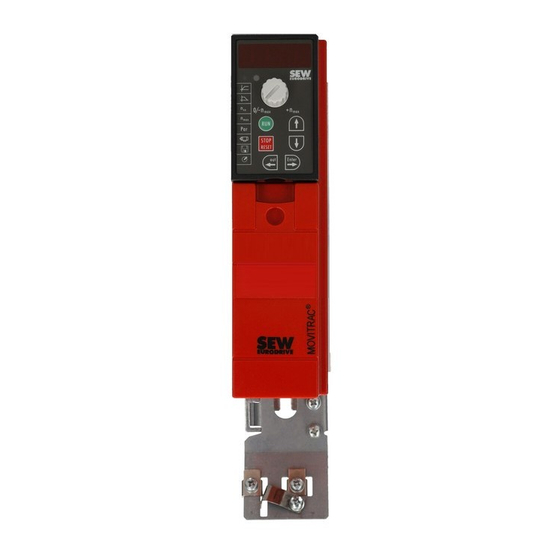
Page 204: Unit Structure
Unit Structure Size 0XS / 0S / 0L Unit Structure Size 0XS / 0S / 0L [14] [13] [12] [11] [10] 9007199279301643 X1: Power supply connection: 3-phase: L1 / L2 / L3 1-phase: L / N Fixing strap PE connection Shield plate for motor cable, fixing strap underneath X2: Motor connection U / V / W / Brake connection +R / -R X17: Safety contact for safe stop... -
Page 205: Size 1 / 2S / 2
Unit Structure Size 1 / 2S / 2 Size 1 / 2S / 2 [14] [13] [12] [11] [10] 9007199346901259 X1: Power supply connection 3-phase: L1 / L2 / L3 / PE screw X4: Connection for DC link coupling –U X3: Braking resistor connection R+ / R–... -
Page 206: Size 3
Unit Structure Size 3 Size 3 [16] [15] [14] [13] [12] [11] [10] 9007199346833675 X2: PE connection X1: Power supply connection 3-phase: 1/L1 / 2/L2 / 3/L3 X4: Connection for DC link coupling –U X3: Braking resistor connection R+ (8) / R– (9) and PE connection X2: Motor connection U (4) / V (5) / W (6) X2: PE connection Electronics shield clamp... -
Page 207: Sizes 4 / 5
Unit Structure Sizes 4 / 5 Sizes 4 / 5 [16] [15] [14] [13] [12] [11] [10] 9007199346827019 X2: PE connection X1: Power supply connection 3-phase: 1/L1 / 2/L2 / 3/L3 X4: DC link connection –U / +U and PE connection X3: Braking resistor connection R+ (8) / R–... -
Page 208: Type Designation
Unit Structure Type designation Type designation The following diagram shows a type designation: MC 07 0022- 2 B 1- 4- 00 /T = Technology unit /L = Paint Design (partially coated cbs) /S = SBus address 1 00 = Standard Design S0 = Safe stop Quadrants... -
Page 209: Installation
Installation Recommended tools Installation DANGER The surface temperatures of the heat sinks can exceed 70 °C. Danger of burns. • Do not touch the heat sink. Recommended tools • Use a screwdriver with a 2.5 mm wide blade for connecting the electronics terminal strip X10 / X12 / X13. - Page 210 Installation Installation notes 8.2.2 Minimum clearance and mounting position • Leave 100 mm (3.94 in) clearance at the top and bottom of the housing for optimum cooling. There is no need for clearance at the sides. You can line up the units directly next to one another.
- Page 211 Installation Installation notes • You can also use earthed sheet-metal ducts or metal pipes to shield the cables. In- stall the power and control cables separately. • Provide high frequency compatible grounding for the inverter and all additional units (wide area metal-on-metal contact between the unit housing and ground, e.g. un- painted control cabinet mounting panel).
- Page 212 Installation Installation notes 8.2.10 Braking resistor connection • Shorten the cables to the required length. • Use 2 tightly twisted leads or a 2-core shielded power cable. Cross-section according to the rated output current of the inverter. • Protect the braking resistor with a bimetallic relay with trip class 10 or 10A (wiring di- agram).
- Page 213 Install fuses at the beginning of the mains cable behind supply bus junction (see basic unit wiring diagram). • SEW-EURODRIVE recommends that you do not use RCDs. However, if an earth- leakage circuit breaker is stipulated for direct or indirect protection against contact, observe the following: •...
-
Page 214: Installing Optional Power Components
Installation Installing optional power components 8.2.17 PE line connection according to EN 61800-5-1 Earth-leakage currents ≥ 3.5 mA can occur during normal operation. Observe the follow- ing for reliable PE connection: • Supply system lead < 10 mm – Route a second PE conductor with the same cross section as the supply system lead in parallel to the protective earth via separate terminals, or –... - Page 215 Installation Installing optional power components 8.3.2 NF line filter ® • Using the NF line filter, you can maintain limit value class C1 / B with MOVITRAC B sizes 0 to 4. • NOTICE Possible damage to property Damage to the input level. ®...
- Page 216 Installation Installing optional power components 8.3.4 HF output filters INFORMATION Install output filters next to the corresponding inverter. Leave a ventilation space of at least 100 mm (3.94 in) below and above the output filter. No clearance is required on the sides.
- Page 217 Only 5 loops are possible if the cable has a large diameter. To make up for this, 2 or 3 output chokes should be connected in series. SEW-EURODRIVE recommends connecting in series 2 output chokes in case of 4 windings and 3 output chokes in case of 3 windings.
- Page 218 Installation Installing optional power components Use the supplied screws to mount the HD100 / HD101 output choke together with the Installation of out- ® MOVITRAC B frequency inverter onto the conductive mounting surface in the control put choke HD100 / cabinet.
- Page 219 Installation Installing optional power components 8.3.7 PTC braking resistors BW1 / BW3 with FKB10B BW1 and BW3 PTC braking resistors [1] can be mounted to the shield plate underneath the inverter using the angle bracket FKB10B [2], part number 1 821 621 available as op- tion.
-
Page 220: Ul Compliant Installation
Installation UL compliant installation 8.3.8 Flat-design resistors with FKB11B / FKB12B / FKB13B and FHS11B / FHS12B / FHS13B Proceed as follows to install flatpack braking resistors: • FKB11B / FKB12B / FKB13B: Installation on the back panel of the control cabinet: •... - Page 221 Installation UL compliant installation 8.4.1 Maximum values/fuses The following maximum values/fuses must be observed for UL compliant installation: 230 V units / 1-phase Max. mains current Max. mains voltage Fuses 0003 / 0004 / 0005 / 0008 AC 5000 A AC 240 V 15 A / 250 V 0011 / 0015 / 0022...
-
Page 222: Loose Items
Installation Loose items Loose items 8.5.1 Scope of delivery of loose items The scope of delivery includes a bag for loose items. Its contents depends on the size of the inverter. Scope of delivery of loose items for size 0XS / 0S / 0L 4 / 5 •... - Page 223 Installation Loose items 8.5.2 Installing shield plate for control electronics (all sizes) ® MOVITRAC B includes a shield plate for the control electron- ics with a retaining screw as standard. Install the shield plate for control electronics as follows: 1. Loosen the screw first [1]. 2.
- Page 224 Installation Loose items ® A shield plate is supplied as standard for the power section with MOVITRAC B size 1. Size 1 Mount the shield plate for the power section using the unit's two retaining screws. 244986123 [1] Shield clamp [2] PE connection A power shield plate for the power section with 2 retaining screws is supplied as stan- Size 2S/2...
- Page 225 • Install the touch guard according to the regulations. • Never start the unit if the touch guard is not installed. SEW-EURODRIVE supplies 2 touch guards for the DC link and braking resistor termi- Size 2S ® ® nals as standard with MOVITRAC B size 2S.
- Page 226 Installation Loose items ® Two touch guards with 8 retaining screws are supplied as standard with MOVITRAC Sizes 4 / 5 sizes 4 / 5. Install the touch guard on both covers of the power section terminals. ® Touch guard for MOVITRAC B sizes 4 / 5: 188886667 The touch guard comprises the following parts:...
-
Page 227: Requirements For Installing Cold Plate (Size 0 Only)
Installation Requirements for installing cold plate (size 0 only) Requirements for installing cold plate (size 0 only) The frequency inverter power loss can be dissipated via coolers that work with different cooling media (air, water, oil, etc.). This can be useful, for example, in restricted instal- lation spaces. - Page 228 Installation Deactivating EMC capacitors (size 0 only) 2. Remove the two screws [A] securing the circuit board. 3. Install the screws in the plastic insulations provided [B]. 4. Fasten screws to the unit [C]. 5. Close the unit. 6. Attach the sticker provided to the unit. 25372555 Deactivating the EMC capacitors stops earth-leakage currents from flowing over the EMC capacitors.
-
Page 229: Wiring Diagram
Installation Wiring diagram Wiring diagram 3 x AC 400/500 V / PE ® MOVITRAC 3 x AC 230 V / PE 1 x AC 230 V / N / PE FSC11B –U PE X4 H L ⊥ 1 2 3 4 5 6 Switchover I-signal ->... -
Page 230: Tf Thermistor And Th Bimetallic Switch
Installation TF thermistor and TH bimetallic switch TF thermistor and TH bimetallic switch The winding temperature is monitored using TF thermistors or TH bimetallic switches. ® Connect TF or TH to the TF output VOTF and the TF input DI05TF of MOVITRAC Set binary input DI05TF to TF signal. -
Page 231: Brake Rectifier Connection
Installation Brake rectifier connection Overload protection for braking resistors BW: Overload protection Braking resistor type Design Internal temperature External bimetallic specified switch (..T / ..P) relay (F16) BW.. – – Required BW..-T / BW..-P – One of the two options (internal temperature switch/ external bimetallic relay) is required. - Page 232 Installation Brake rectifier connection 8.11.1 Wiring diagrams DOØ2 Cut-off in the Cut-off in the Cut-off in the DC and AC circuit DC and AC circuit AC circuit 9007199909369355 Note the corresponding connection regulations for brakes without BG/BGE or BME. Refer to the SEW publication "Drive Engineering - Practical Implementation:: SEW Disk Brakes".
-
Page 233: Installing Fio11B/21B, Fsc11B/12B And Fse24B
Installation Installing FIO11B/21B, FSC11B/12B and FSE24B 8.12 Installing FIO11B/21B, FSC11B/12B and FSE24B You can enhance the basic units with the FIO11B/21B, FSC11B/12B and FSE24B mod- ules. FSC12B FSE24B FIO11B FIO21B FSC11B X45 X40 X30 IN X30 OUT H L ⊥ H L ⊥... - Page 234 Installation Installing FIO11B/21B, FSC11B/12B and FSE24B Function Terminal Description Data FIO11B FIO21B FSC11B/ FSE24B System bus X46:1 SC11: SBus high CAN bus to CAN spec- ification 2.0, parts A X46:2 SC12: SBus low and B X46:3 GND: Reference Max. 64 stations potential X46:4 SC21: SBus high...
- Page 235 Installation Installing FIO11B/21B, FSC11B/12B and FSE24B The DC 24 V potential of X46:7 is identical to X12:8 of the basic unit. All GND terminals of the unit are connected to each other and to PE. Cable specification • Use a 4-core twisted and shielded copper cable (data transmission cable with braided copper shield).
- Page 236 Installation Installing FIO11B/21B, FSC11B/12B and FSE24B 8.12.2 Wiring the FIO11B analog module Analog input AI1 Analog output AO1 Bipolar Unipolar Current output AOC1 Voltage output AOV1 X45 X40 X45 X40 X45 X40 X45 X40 H L ⊥ H L ⊥ H L ⊥...
- Page 237 Installation Installing FIO11B/21B, FSC11B/12B and FSE24B 8.12.4 Installation RS485 interface on FSC11B / 12B ® The RS485 interface enables you to interconnect up to 32 MOVITRAC B units. ® RS485 connection MOVITRAC ® ® ® MOVITRAC MOVITRAC MOVIDRIVE DGND FSC11B / 12B FSC11B / 12B ST11 FIO11B...
- Page 238 Installation Installing FIO11B/21B, FSC11B/12B and FSE24B ® MOVITRAC B system bus connection ® ® ® MOVITRAC MOVITRAC MOVIDRIVE ON OFF X12: DGND SC11 FSC11B / 12B FSC11B / 12B SC12 3 H L ⊥ H L ⊥ 1 2 3 4 5 6 1 2 3 4 5 6 9007199279915787 ®...
- Page 239 Installation Installing FIO11B/21B, FSC11B/12B and FSE24B ® MOVITRAC B system bus connection with DFx/UOH11B gateways or DFx integrated ® in MOVITRAC UOH11B DFP21B FAULT ® MOVITRAC ADDRESS FSC11B / 12B H L ⊥ 1 2 3 4 5 6 1 2 3 4 5 6 7 + 24 V 9007199494905355 Cable length...
-
Page 240: Installing The Mbg11A Speed Control Module
Installation Installing the MBG11A speed control module Use a 4-core twisted and shielded copper cable (data transmission cable with braided Cable specification copper shield). The cable must meet the following specifications: – Cable cross section 0.25 – 0.75 mm (AWG23 – AWG18) –... - Page 241 Installation Installing the MBG11A speed control module 8.13.1 Connection ® MOVITRAC FSC11B MBG11A H L ⊥ 1 2 3 4 5 6 1 2 3 4 188285707 Phone: 800.894.0412 - Fax: 888.723.4773 - Web: www.clrwtr.com - Email: info@clrwtr.com System Manual – MOVITRAC® B...
-
Page 242: Startup
B frequency inverters are factory set to be taken into operation with the SEW motor adapted to the correct power level (4-pole, 50 Hz) in V/f control mode. Thus you can startup the adjusted SEW-EURODRIVE motor without project planning. 9.1.2... - Page 243 Startup Preliminary work and resources 9.2.1 Preliminary work and tools for startup with factory setting • Connect the supply system and the motor. • Connect the signal terminals. • Switch on the power supply system. 9.2.2 Preliminary work and tools for startup with keypad or with PC •...
-
Page 244: Starting The Motor
Startup Starting the motor Starting the motor You have to exit manual operation before you can enable the motor via terminals. 9.3.1 Analog setpoint specification The following table shows which signals must be present on terminals X11:2 (AI1) and X12:1 – X12:4 (DIØØ – DIØ3) when the "unipolar/fixed setpoint" setpoint is selected (P100) in order to operate the drive with an analog setpoint entry. - Page 245 Startup Starting the motor The following travel cycle shows by way of example how the motor is started with the assignment of terminals X12:1 – X12:4 and analog setpoints. Binary output X10:3 (DBØØ "/Brake") is used for switching brake contactor K12. Input DIØØ...
- Page 246 Startup Starting the motor 9.3.2 Fixed setpoints The following table shows which signals must be present on terminals X12:1 – X12:6 (DIØØ – DIØ5) when the "unipolar/fixed setpoint" setpoint is selected (P100) in order to operate the drive with the fixed setpoints. X12:1 X12:2 X12:3...
- Page 247 Startup Starting the motor The following travel cycle shows by way of example how the drive is started with the as- signment of terminals X12:1 – X12:6 and the internal fixed setpoints. Binary output X10:3 (DBØØ "/Brake") is used for switching brake contactor K12. Input DIØØ...
-
Page 248: Startup Of Explosion-Proof Ac Asynchronous Motors Of Category 2 (94/9/Ec)
Startup Startup of explosion-proof AC asynchronous motors of category 2 (94/9/EC) Startup of explosion-proof AC asynchronous motors of category 2 (94/9/EC) Explosion-proof AC motors from SEW-EURODRIVE that are taken into operation with ® MOVITRAC B must be approved for such operation according to the nameplate and EC type examination certificate. -
Page 249: Startup With Factory Setting - Brief Description
Startup Startup with factory setting – brief description Startup with factory setting – brief description ® You can directly connect the MOVITRAC B frequency motor to a motor with the same power rating. For example: A 1.5 kW (2.0 HP) motor can be connected directly to a MC07B0015. -
Page 250: Keypad Fbg11B
Startup Keypad FBG11B Keypad FBG11B Key arrangement and symbols on the keypad: 9007199348841739 [1] LED display with IPOS program started 9.6.1 Keypad functions The UP/DOWN and ENTER/OUT buttons are used for navigating through the menus. Use the RUN and STOP/RESET buttons to control the drive. The speed control module is used for setpoint specification. - Page 251 Startup Keypad FBG11B ® After copying the parameter set in MOVITRAC B, the unit is also stopped. 9.6.2 General operation of the FBG11B keypad Level 1 Level 2 Display inverter status speed out Enter Edit Edit/apply Display Enter ramp up value rampe up Edit...
- Page 252 Startup Keypad FBG11B The LED integrated in the symbol lights up when you select a symbol. If a symbol only Menu system represents display values, the current display value appears immediately on the display. You can select the required parameter by selecting a symbol and pressing the ENTER Changing parame- key.
- Page 253 Startup Keypad FBG11B 9.6.3 Startup using the FBG11B keypad Level 2 Level 3 Motor selection: – SEW DT/DV motor – Non-SEW motor Level 1 out Enter – SEW DRS motor out Enter – SEW DRE motor out Enter Operating mode selection: –...
- Page 254 Startup Keypad FBG11B The following data is required to ensure startup is successful: Required data • Motor type (SEW or non-SEW motor) • Motor data – Rated voltage and rated frequency – Additionally for non-SEW motors: Nominal current, nominal power, power factor cos ϕ, and nominal speed.
- Page 255 Startup Keypad FBG11B Multi-motor drives are mechanically coupled to each other (e.g. chain drive with multiple Startup of multi- motors). motor drive ® Observe the notes in the "MOVIDRIVE Multi-Motor Drives" manual. Group drives are mechanically decoupled from each other (e.g. different conveyor Startup of group belts).
-
Page 256: Startup With Dbg60B Keypad
Startup Startup with DBG60B keypad Startup with DBG60B keypad 9.7.1 Required data The following data is required to ensure startup is successful: • Motor type (SEW or non-SEW motor) • Motor data – Rated voltage and rated frequency – Additionally for non-SEW motors: Nominal current, nominal power, power factor cos ϕ, and nominal speed. - Page 257 Startup Startup with DBG60B keypad The symbol for language selection then appears on the display. Proceed as follows to select the language: • Press the language button. A list of languages is displayed on the screen. • Choose the desired language using the ↑ / ↓ keys. •...
- Page 258 Startup Startup with DBG60B keypad 9.7.4 Startup procedure 1. Enter "0" signal at terminal X12:2 (DIØ1 "/CW/STOP), 0.00rpm 0.000Amp e.g. by disconnecting X12 the electronics terminal CONTROLLER INHIBIT block. 2. Press the context key to activate the context menu. PARAMETER MODE VARIABLE MODE BASIC VIEW 3.
- Page 259 Startup Startup with DBG60B keypad 7. Select the motor type. If a 2 or 4-pole SEW-EURO- C02*MOTOR TYPE 1 DT71D2 DRIVE motor is connected, select the correct motor DT71D4 from the list. DT80K2 If a non-SEW motor or an SEW motor with more than four poles is connected, select "NON-SEW MOTOR"...
- Page 260 Startup Startup with DBG60B keypad 10. Enter the following motor nameplate data: C47*4-Q OPERATION • C10* Observe rated motor current, connection type • C11* rated motor power • C12* power factor cos ϕ • C13* rated motor speed 11. Enter the rated power supply voltage (C05* for SEW C05* NOM.
- Page 261 Startup Startup with DBG60B keypad • Enter any parameter settings which differ from the factory settings in the parameter list. • In the case of non-SEW motors, set the correct brake application time (P732 / P735). • Observe the notes for starting the motor in chapter "Starting the Motor". •...
- Page 262 Startup Startup with DBG60B keypad 9.7.7 Manual operation The inverter can be controlled using the DBG60B keypad in manual operation (Context menu → Manual operation). The binary inputs will be without any functions for the duration of manual operation, with the exception of a "/Controller"...
-
Page 263: Startup With Pc And Movitools ® Motionstudio
Startup ® Startup with PC and MOVITOOLS MotionStudio ® Startup with PC and MOVITOOLS MotionStudio ® Start MOVITOOLS MotionStudio in the Windows start menu: Programs / SEW / MOVITOOLS MotionStudio 5.x / MotionStudio 5.x ® Press the MOVITOOLS MotionStudio [Scan] button to list all connected units in the unit tree. -
Page 264: External Setpoint Selection
Startup External setpoint selection External setpoint selection External setpoint selection Control via – Terminals – Serial interface – Setpoint potentiometer connected to AI11/AI12 9.9.1 Set direction of rotation You can set the direction: • "CW/Stop and "CCW/Stop" in P101 control signal source = terminals or P101 control signal source = 3 wire-control •... - Page 265 Startup External setpoint selection 9.9.4 Startup for MBG11A speed control module ® You cannot simultaneously establish communication between MOVITRAC ® MBG11A and MOVITRAC B / PC via RS485. ® The MBG11A can simultaneously specify a setpoint for up to 31 MOVITRAC B units.
-
Page 266: Parameter List
Startup Parameter list 9.10 Parameter list All parameters that can also be displayed and edited using the keypad are indicated as follows in the "FBG" (keypad) column: Selection in the long menu (P800 = long) Selection in the short or long menu (P800 = short) Display in the pictogram menu in the FBG11B keypad Selection within FGB motor startup If there are several options, the factory setting is underlined. - Page 267 Startup Parameter list Index Name Range / factory setting dec. ® Display MOVITOOLS MotionStudio 8334 Binary inputs DI00 Collective display of binary inputs – DI05 Binary inputs option (see parameter P60.) Binary input DI10 No function Binary input DI11 No function Binary input DI12 No function Binary input DI13...
- Page 268 Startup Parameter list Index Name Range / factory setting dec. ® Display MOVITOOLS MotionStudio Bus diagnostics 8451 PD configuration 8452 Fieldbus type 8453 Fieldbus baud rate 8454 Fieldbus address 8455 PO 1 setpoint 8456 PO 2 setpoint 8457 PO 3 setpoint 8458 PI 1 actual value 8459...
- Page 269 Startup Parameter list Index Name Range / factory setting dec. ® Display MOVITOOLS MotionStudio 8465 AI1 operating mode 1 10 V, reference potential maximum speed 0 – 20 mA, reference maximum speed 4 – 20 mA, reference maximum speed 0 – 10 V, n-reference 0 –...
- Page 270 Startup Parameter list Index Name Range / factory setting dec. ® Display MOVITOOLS MotionStudio 160 / 170 8489 / Internal setpoint 0 – 150 – 5000 rpm 8492 n11 / n21 161 / 171 8490 / Internal setpoint 0 – 750 – 5000 rpm 8493 n12 / n22 162 / 172...
- Page 271 Startup Parameter list Index Name Range / factory setting dec. ® Display MOVITOOLS MotionStudio Speed reference signal 8539 Speed reference 0 – 750 – 5000 rpm value 8540 Hysteresis 0 – 100 – +500 rpm 8541 Deceleration time 0 – 1 – 9 s 8542 Message = "1"...
- Page 272 Startup Parameter list Index Name Range / factory setting dec. ® Display MOVITOOLS MotionStudio 9294 Frequency A 0 – 5 – 60 Hz 9295 Current limit A 0 – 50 – 150 % 9296 Frequency B 0 – 10 – 104 Hz 9297 Current limit B 0 –...
- Page 273 Startup Parameter list Index Name Range / factory setting dec. ® Display MOVITOOLS MotionStudio No function 8350 Binary output DO01 assignment /Malfunction (factory setting DO01) Ready (factory setting DO03) 8351 Binary output DO02 assignment Output stage ON Rotating field ON 8916 Binary output DO03 assignment...
- Page 274 Startup Parameter list Index Name Range / factory setting dec. ® Display MOVITOOLS MotionStudio 710 / 711 8576 / Standstill current 0 – 50% I 8577 1 / 2 Setpoint stop function 1 / 2 720 / 723 8578 / Setpoint stop func- 8581 tion 1 / 2...
- Page 275 Startup Parameter list Index Name Range / factory setting dec. ® Display MOVITOOLS MotionStudio – Copy DBG → ® MOVITRAC ® – Copy MOVITRAC B → DBG 10204.3 24 V output voltage 10204.1 IPOS enable – Serial communication 8597 RS485 address 0 –...
- Page 276 Startup Parameter list Index Name Range / factory setting dec. ® Display MOVITOOLS MotionStudio 860 / 861 8620 / PWM frequency 4 kHz 8621 1 / 2 8 kHz 12 kHz 16 kHz 862 / 863 8751 / PWM fix 1 / 2 8752 Process data parameter setting 8304...
-
Page 277: Operation
Operation Data backup Operation 10.1 Data backup 10.1.1 Data backup using FBG11B ® Use the FBG11B keypad to download parameter data from the MOVITRAC B to the ® keypad or copy from the keypad to MOVITRAC Check that the required data set has been copied to the inverter. Data backup with FBG11B Level 1 Level 2... -
Page 278: Return Codes (R19 - R38)
Operation Return codes (r19 – r38) ® 10.1.4 Data backup using MOVITOOLS MotionStudio ® ® When you use MOVITOOLS MotionStudio to transfer data to the MOVITRAC B fre- quency inverter, you must re-enable the inverter as follows: • Select the unit in the network •... -
Page 279: Status Displays
Operation Status displays 10.3 Status displays 10.3.1 Basic unit / keypad FBG11B The status displays on the unit are as follows: State Display (optionally with Basic unit status LED flash Unit status (high FBG11B key pad) code byte in status word 1) "ENABLE"... - Page 280 Operation Status displays The controller inhibit (OFF) can be caused by the following conditions: Cause for control- ler inhibit (OFF) • Binary input terminal (DI00, DI02 – DI05) programmed to controller inhibit and acti- vated. ® • Controller inhibit due to PC manual mode via MOVITOOLS MotionStudio.
-
Page 281: Dbg60B Keypad
Operation DBG60B keypad 10.4 DBG60B keypad 10.4.1 Basic displays 0.00rpm Display when /CONTROLLER INHIBIT = "0". 0.000Amp CONTROLLER INHIBIT 0.00rpm Display when inverter is not enabled ("ENABLE/STOP" = 0.000Amp "0"). NO ENABLE 950.00rpm Display for enabled inverter. 0.990Amp ENABLE (VFC) Information message NOTE 6: VALUE TOO HIGH... - Page 282 Operation DBG60B keypad 10.4.2 Information messages ® Information messages on the DBG60B (ca. 2 s in duration) or in MOVITOOLS Motion- Studio/SHELL (message that can be acknowledged): No. Text DBG60B/SHELL Description ILLEGAL INDEX Index addressed via interface not available. • Attempt to execute a function that is not implemented.
- Page 283 Operation DBG60B keypad 10.4.3 Functions of the DBG60B keypad Key assignments for DBG60B [12] [11] [10] 247460747 STOP key Stop ↑ key Up arrow, moves up to the next menu item RUN key Start OK key OK, confirms the entry Context key Activate the context menu ↓...
- Page 284 Operation DBG60B keypad Proceed as follows to set the parameters in parameter mode: Parameter mode DBG60B 1. Press the context key to activate the context menu. PARAMETER MODE VARIABLE MODE The first menu item is "PARAMETER MODE". BASIC VIEW 2. Press the OK key to start PARAMETER MODE. The P 000 SPEED first display parameter P000 "SPEED"...
- Page 285 Operation DBG60B keypad 11. Use the ↑ or ↓ key to select another parameter, or \ 13. SPEED RAMPS 1 press the DEL key to switch to the menu of the param- eter subgroups. CONTROLLER INHIBIT 12. Use the ↑ or ↓ key to select another parameter sub- P 1..
-
Page 286: Service / List Of Errors
Service / List of Errors Unit information Service / List of Errors 11.1 Unit information 11.1.1 Error memory The inverter stores the error message in fault memory P080. The inverter does not save a new fault until the error message has been acknowledged. The local operating panel shows the most recent error. -
Page 287: Error List (F00 - F113)
Service / List of Errors Error list (F00 – F113) Rapid stop/warning (stop without locking) The error response corresponds to rapid stop/malfunction but the inverter does not re- voke the ready signal and the error output is set. Timeout RS485 / SBus: If the inverter is controlled via a communication interface (RS485 or SBus) and the mains power was switched off and back on again, the enable remains ineffective until the inverter once again receives valid data via the interface, which is monitored with a... - Page 288 Service / List of Errors Error list (F00 – F113) Designation Response Possible cause Measure Brake chopper Immediate switch- • Too much regenerative power • Extend deceleration ramps off with inhibit. • Braking resistor circuit inter- • Check supply cable to the brak- rupted ing resistor •...
- Page 289 Service / List of Errors Error list (F00 – F113) Designation Response Possible cause Measure TF/TH sensor Stop without inhibit • Motor too hot, TF sensor has • Let motor cool off and reset tripped error tripped • "Ready" signal is maintained •...
- Page 290 "DUV10A diagnostics unit" operation possible until F101 operating instructions) Vibration error Rapid stop • Vibration sensor signals error • SEW-EURODRIVE recom- mends that you remedy the cause of the vibrations immedi- ately Oil aging/warn- Display error • Oil aging sensor warns •...
- Page 291 Service / List of Errors Error list (F00 – F113) Designation Response Possible cause Measure Brake wear Display error • Brake lining worn • Replace brake lining (see "Motors" operating instructions) Ex-e protection Emergency stop • Duration of operation below 5 •...
-
Page 292: Sew Electronics Service
SEW electronics service 11.3.1 Hotline Call the Drive Service Hotline to talk to an SEW-EURODRIVE service specialist on 365 days a year, 24 hours a day. Simply dial the prefix 01805 and then enter the key combination SEWHELP. Or simply dial 01805 739 4357. -
Page 293: Extended Storage
This effect can damage the capacitors if the unit is connected using the rated voltage after a longer period of storage. If you have not performed maintenance regularly, SEW-EURODRIVE recommends that you increase the line voltage slowly up to the maximum voltage. This can be done, for example, by using a variable transformer for which the output voltage has been set ac- cording to the following overview. -
Page 294: Address List
Index Index Braking resistor............60 BW, connection..........230 AC brakemotors, connection........166 Connection............212 Active current, display value ........103 FKB10B, mounting..........68 Actual value description PI......149, 150 Flat design ..........61, 163 Addition FBG speed control module ....113 Grid resistor ..........62, 163 Address PTC............60, 162 CANopen ............151 Submounting............68 AI1 characteristic curve........112... - Page 295 Index cUL.................15 Dimension drawings Current limit............119 Braking resistors BW... / BW...-T / BW...-P..65 Current limitation ..........127 BW1.4-170 braking resistor .......67 Current parameter set ..........104 DBG60B.............49 Current reference value ........124 DBM60B/DKG60B ..........50 HF...-403 output filter .........84 HF...-503 output filter .........83 Line choke ND020.. / ND030.. / ND045.. / Data backup ..........251, 277 ND085..............72 DBG60B............277...
- Page 296 Index Error External setpoint potentiometer ......191 F04 Brake chopper ..........288 External setpoint selection........264 F06 Mains phase failure........288 External voltage supply DC 24 V ....18, 182 F07 DC link overvoltage........288 F08 Speed monitoring........288 F09 startup............288 Factory setting .............143 F10 IPOS-ILLOP..........288 Fault F100 vibration/warning........290 F01 Overcurrent..........287...
- Page 297 Index Front module FSC11B communication module ..43 Keypad DBG60B Front modules ............39 Setting parameters .......... 261 Front option FSC12B communication ....44 Startup ............. 256 FSC11B communication interface....43, 233 Keypad FBG11B..........250 FSC12B communication interface......44 Functions ............250 FSE24B..............233 Operation ............251 FSE24B EtherCAT module ........46 Startup .............
- Page 298 Index Motor startup ............251 Parameter set ............104 Mounting position ..........210 Parameter set selection ........184 ® MOVI-PLC ............95 Parameters ® MOVI-PLC controller..........95 Control functions..........135 ® MOVITOOLS MotionStudio, startup....263 Controller parameters ........117 Multi-motor drive ..........174, 255 Display values..........103 Monitoring functions......... 125 Motor parameters ..........
- Page 299 Index Safety contact ............18 Safety notes............199 Ramp Designation in the documentation ....197 down ..............251 Structure of the embedded safety notes..197 Monitoring ............116 Structure of the section-related safety notes ... 197 t11/t21 up ............115 Save last setpoint ..........116 t3 motor potentiometer........116 SBus Up ..............251...
- Page 300 Index Speed Supply system lead..........211 Display value............103 Support rail mounting Manual setting..........255 Braking resistor..........70 Maximum ............255 Switched-mode power supply UWU52A ....101 Minimum ............255 Switch-off response Monitoring ............125 Immediate switch-off........286 Ramps..............115 Stop ..............286 Reference signal ..........123 Switch-off responses ...........286 Speed control module ..........251 System bus (SBus), installation ......237 Manual .............255 System overview............8...
- Page 301 Index UWU52A..............101 UBP11A ..............51 UL approval............15 UL compliant installation ........220 VFC..............254 ULF11A folding ferrites ........75, 215 Voltage drop ............173 Unit data...............106 Motor cable ............169 Unit design Voltage supply system......... 167 Size 0XS / 0S / 0L..........204 Voltage supply, external DC 24 V ......182 Size 1 / 2S / 2...........205 Voltage-frequency characteristic curve....
Need help?
Do you have a question about the MOVITRAC B MC07B0003-2B1-4-00 and is the answer not in the manual?
Questions and answers