
Related Manuals for SEW-Eurodrive MOVIFIT-FC


Summary of Contents for SEW-Eurodrive MOVIFIT-FC
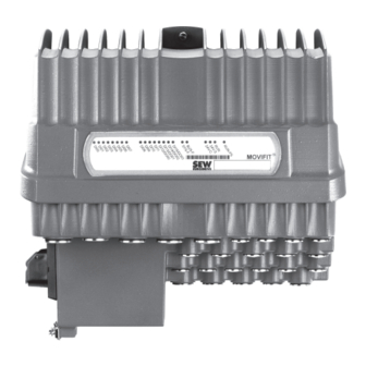
- Page 1 Drive Technology \ Drive Automation \ System Integration \ Services Special Design ® MOVIFIT -FC for Dual-Motor Operation Addendum to the Operating Instructions Edition 03/2009 16784413 / EN...
- Page 2 SEW-EURODRIVE – Driving the world...
-
Page 3: Table Of Contents
Rights to claim under limited warranty ............5 Exclusion of liability..................5 Other applicable documentation ..............5 Unit Structure ...................... 6 Special design "MOVIFIT-FC for dual-motor operation" ......6 Accessories....................8 Electrical Installation ..................9 Fieldbus/option-independent terminal assignment ........9 Replacing switching relays................ -
Page 4: General Information
General Information Structure of the safety notes General Information Structure of the safety notes The safety notes in these operating instructions are designed as follows: Pictogram SIGNAL WORD Type and source of danger. Possible consequence(s) if the safety notes are disregarded. •... -
Page 5: Rights To Claim Under Limited Warranty
General Information Rights to claim under limited warranty Rights to claim under limited warranty A requirement of fault-free operation and fulfillment of any rights to claim under limited warranty is that you adhere to the information in the operating instructions. Therefore, read the operating instructions before you start working with the unit Make sure that the operating instructions are legible and available to persons responsi- ble for the plant and its operation, as well as to persons who work independently on the... -
Page 6: Unit Structure
Unit Structure Special design "MOVIFIT-FC for dual-motor operation" Unit Structure Special design "MOVIFIT-FC for dual-motor operation" TIPS This special design ""MTA...-S..-30." comprises the following changes on the connec- tion box compared to the standard design: • Modified connection assignment of the ABOX. - Page 7 Unit Structure Special design "MOVIFIT-FC for dual-motor operation" 2.1.1 Example of an ABOX unit designation MT A 11 A - 50 3 -S02 1 - D 01 - 30 / BW1 ABOX option BW1 / BW2 = Integrated braking resistor...
-
Page 8: Accessories
Unit Structure Accessories Accessories The following accessories are required for replacing faulty relays. The relays can also be replaced during maintenance to increase system availability. The accessories are available from SEW-EURODRIVE. Type Figure Content Part number Switching relay including support 3 pc 1 821 747 8 bracket... -
Page 9: Electrical Installation
Electrical Installation Fieldbus/option-independent terminal assignment Electrical Installation TIPS • The following section describes the modified connection assignment of the ABOX. • For the terminal assignment of all terminals that are not described here, refer to the ® "MOVIFIT -FC" operating instructions. ®... - Page 10 Electrical Installation Fieldbus/option-independent terminal assignment 1 2 3 6 7 8 1 2 3 4 5 1 2 3 4 1 2 3 4 11 12 1 13 1 14 1 2 3 1 1 2 2 3 3 4 4 5 1 2 3 3 4 5 6 7 8 2 3 5 6 11 12 13 14 15 16 17 18...
- Page 11 Electrical Installation Fieldbus/option-independent terminal assignment 1 2 3 6 7 8 1 2 3 4 5 1 2 3 4 1 2 3 4 11 12 1 13 1 14 1 2 3 1 1 2 2 3 3 4 4 5 1 2 3 3 4 5 6 7 8 2 3 5 6 11 12 13 14 15 16 17 18...
- Page 12 Electrical Installation Fieldbus/option-independent terminal assignment 1 2 3 1 2 3 4 5 6 7 8 1 2 3 4 1 2 3 4 11 12 1 13 1 14 1 2 3 1 1 2 2 3 3 4 4 5 1 2 3 3 4 5 6 7 8 2 3 5 6 11 12 13 14 15 16 17 18...
-
Page 13: Replacing Switching Relays
Electrical Installation Replacing switching relays Replacing switching relays You can replace the K1, K2 or K3 switching relays as follows: DANGER Disconnect the units from power before installing/removing the relay. Dangerous volt- ages may still be present for up to one minute after disconnection from the power sup- ply. -
Page 14: Startup
Startup ® Startup procedure for MOVIFIT Startup ® Startup procedure for MOVIFIT ® The following sections describe how to startup the special design MOVIFIT -FC motor. Observe the additional documents listed in the following table: ® Fieldbus configuration Motor MOVIFIT -SC/-FC Parameterization Programming... -
Page 15: Preparations
Startup Preparations Preparations ® 4.2.1 MOVITOOLS MotionStudio ® The "MOVITOOLS MotionStudio" software package is the SEW engineering tool that you can use to access all SEW drive units. With simple applications, you can use ® ® MOVITOOLS MotionStudio to perform diagnostics for the MOVIFIT unit series. - Page 16 Startup Preparations ® 4. Connect MOVIFIT to the PC or laptop using the option USB11A or UWS21B: MOVIFIT ® UWS21B RS-232 RS-485 RJ10 USB11A RS-485 RJ10 792913419 ® Option USB11A or UWS21B can be connected to MOVIFIT using the diagnostics socket X50.
- Page 17 Startup Preparations ® ® Including MOVIFIT in MOVITOOLS MotionStudio ® Starting the soft- Proceed as follows to start MOVITOOLS MotionStudio and create a project: ware and creating ® 1. Start the MOVITOOLS MotionStudio from the Windows start menu via: a project [Start]/[Programs]/[SEW]/[MOVITOOLS-MotionStudio]/[MOVITOOLS-MotionStudio] 2.
-
Page 18: Motor/Brake Startup With Movifit ® -Fc
Startup ® Motor/brake startup with MOVIFIT ® Motor/brake startup with MOVIFIT "Expert mode" (S10/1 = "ON") must be active for the following motor/brake startup pro- cedure. 4.3.1 Starting up drive 1 ® 1. Choose the startup tool in MOVITOOLS MotionStudio (see section "Including ®... - Page 19 Startup ® Motor/brake startup with MOVIFIT 3. After you have selected the parameter set, an overview displaying the current unit information is displayed (display values only): 792945035 4. Select the configuration for the motor output: • Activate the "Switchable" checkbox. 1771084939 Addendum to the Operating Instructions –...
- Page 20 Startup ® Motor/brake startup with MOVIFIT 5. Select the system configuration: ® • With "one motor", MOVIFIT -FC controls a single motor. ® • With "rigid coupling", MOVIFIT -FC controls several motors that are rigidly coupled via the axes. ® •...
- Page 21 Startup ® Motor/brake startup with MOVIFIT 6. Select the control mode: • The vector-controlled operating mode (VFC) is adapted for use with SEW motors. • For non-SEW motors, select the operating mode U/f characteristic curve when the VFC operating mode does not produce a satisfactory result. 792950027 7.
- Page 22 Startup ® Motor/brake startup with MOVIFIT 8. Choose the connected motor. 792951691 Standard motors: When selecting an SEW standard motor, select: • the motor type • the rated motor voltage (corresponding to the respective type of connection, "Star" or "Delta") •...
- Page 23 Startup ® Motor/brake startup with MOVIFIT 9. With brakemotors, once motor startup has been concluded, you must now select the brake: 792958347 Standard SEW brake control: ® • If the motor is equipped with the brake intended for the MOVIFIT drive, –...
- Page 24 Startup ® Motor/brake startup with MOVIFIT Alternative brake control CAUTION When selecting an alternative brake control, the drive must already be equipped with an internal or external braking resistor. During the brake process, the braking resistor dissipates regenerative power. The alternative brake control is intended for the case •...
- Page 25 Startup ® Motor/brake startup with MOVIFIT ® ® For the assignment of MOVIFIT motors to Standard brakes, refer to the "MOVIFIT FC" operating instructions, ® chapter "Startup"/"Startup of MOVIFIT frequency inverters"/"Startup in Easy mode"/ "DIP switch10/5". For DT/DV motors, the brake type is not stated explicitly. You can determine the type of the installed brake on the basis of the motor size and the specified braking torque (see motor nameplate).
- Page 26 Startup ® Motor/brake startup with MOVIFIT 10.The next step "Application parameters" is used to activate the "Speed monitoring" function and to set the current limit. When speed monitoring is active, a fault is triggered after the specified deceleration time when the output current reaches the set current limit continuously. The percentage current level is based on the rated unit current.
- Page 27 Startup ® Motor/brake startup with MOVIFIT 11.In the next step parameters are set for the speed limits and ramp times. The ramp times are always based on a change in the output speed of 1500 rpm. The ramp times apply when a ramp time has not been specified via the process data and an enable/revoke enable occurs.
- Page 28 Startup ® Motor/brake startup with MOVIFIT 12.Click the "Download" or "Finish" button to download the parameters to the unit. Be- fore you download the parameters, you can switch to any of the previous pages. The settings are not lost. 906417803 Startup of a hoist drive is not permitted with this special design.
- Page 29 Startup ® Motor/brake startup with MOVIFIT 4.3.2 Starting up drive 2 1. Startup of drive 1 must have been completed successfully by clicking on the button "Finish". ® 2. Choose the startup tool in MOVITOOLS MotionStudio (see section "Including ® ®...
-
Page 30: Switchover Between Drive 1 And Drive 2
Startup Switchover between drive 1 and drive 2 Switchover between drive 1 and drive 2 ® 4.4.1 Switching via MOVIFIT -FC control word- ® Bit 5 "Parameter set switchover" in the MOVIFIT -FC control word is used for switching between drive 1 and drive 2. A switchover is only possible when the output stage is inhibited (evaluation via status word 1, bit 0, (see page 31)). - Page 31 Startup Switchover between drive 1 and drive 2 ® 4.4.2 Evaluation via status word 1 for MOVIFIT ® Bit 4 "Current parameter set" in the MOVIFIT -FC status word 1 is used for determining which drive has been activated via the control word: Byte n+1 Byte n 15 14 13 12 11 10 9...
- Page 32 Drive Technology \ Drive Automation \ System Integration \ Services How we’re driving the world With people who With comprehensive With uncompromising think fast and With a worldwide With drives and controls knowledge in virtually quality that reduces the develop the service network that is that automatically every branch of...
Need help?
Do you have a question about the MOVIFIT-FC and is the answer not in the manual?
Questions and answers