
Related Manuals for ADCMT 4601 I-V Meter


Summary of Contents for ADCMT 4601 I-V Meter
- Page 1 Cover 4601 I-V Meter Operation Manual FOE-00000066A00 MANUAL NUMBER First printing Sep 22, 2011 ADC CORPORATION 2011 All rights reserved. Printed in Japan...
- Page 3 Safety Summary Safety Summary To ensure thorough understanding of all functions and to ensure efficient use of this instrument, please read the manual carefully before using. Note that ADC Corporation (hereafter referred to as ADC) bears absolutely no re- sponsibility for the result of operations caused due to incorrect or inappropriate use of this instrument. If the equipment is used in a manner not specified by ADC, the protection provided by the equipment may be im- paired.
- Page 4 Safety Summary product. • When the product has ventilation outlets, do not stick or drop metal or easily flammable ob- jects into the ventilation outlets. • When using the product on a cart, fix it with belts to avoid its drop. •...
- Page 5 Safety Summary Main Parts with Limited Life Part name Life Unit power supply 5 years Fan motor 5 years Electrolytic capacitor 5 years LCD display 6 years LCD backlight 2.5 years Floppy disk drive 5 years Memory backup battery 5 years •...
- Page 6 Environmental Conditions This instrument should be only be used in an area which satisfies the following conditions: • An area free from corrosive gas • An area away from direct sunlight • A dust-free area • An area free from vibrations •...
- Page 7 Types of Power Cable Replace any references to the power cable type, according to the following table, with the appropriate power cable type for your country. Rating, color Model number Plug configuration Standards and length (Option number) PSE: Japan 125 V at 7 A Straight: A01402 Black...
-
Page 9: Table Of Contents
TABLE OF CONTENTS 4601 I-V Meter Operation Manual TABLE OF CONTENTS PREFACE ...................... Product Overview ....................Supplied Accessories ..................Output Unit ......................1.3.1 Removing Panel ..................1.3.2 Mounting Output Unit ................Optional Accessories ..................1-10 Options ......................1-10 Operating Environment .................. - Page 10 4601 I-V Meter Operation Manual Table of Contents Sweep Source Mode ..................3-12 3.3.1 Sweep Source and Measurement Method ..........3-12 3.3.2 Checking Measured Values ................ 3-13 3.3.3 Setting Current Limits ................3-14 3.3.4 Changing Reference Cell Current Range ...........
- Page 11 4601 I-V Meter Operation Manual Table of Contents 5.2.2 Sweep Source Mode ................... 5.2.3 Reverse Function ..................5-10 5.2.4 Output at Sweep End .................. 5-11 5.2.5 Source and Measurement Timings ............. 5-11 5.2.5.1 Basic Source and Measurement Timings ........... 5-11 5.2.5.2...
- Page 12 4601 I-V Meter Operation Manual Table of Contents 6.3.3 Connecting with PC ..................6.3.4 Precautions when Using USB ..............6.3.5 Setting USB ID ................... Status Register Structure ................... Data Output Format ................... 6-15 6.5.1 Measured Value Output ................6-15 6.5.2 Output Target Selection ................
- Page 13 4601 I-V Meter Operation Manual Table of Contents SPECIFICATIONS ..................Voltage Source/Voltage Measurement/Current Measurement Terminal OUTPUT/SENSE Terminal ................Voltage Measurement Terminal Em Terminal ...................... Reference Cell Measurement Terminal CELL Ir Terminal ..................... Temperature Measurement Thermocouple Measurement Terminal Tc1/Tc2 Terminal ....................
- Page 15 4601 I-V Meter Operation Manual LIST OF ILLUSTRATIONS Title Page 4601 Configuration ......................Output Range ........................Maximum Power Limitation at Time of Continuous Loading ......... Duty Ratio Limitation at Time of 300 W (Sink)/30 W (Source) Loading ....... Mounting Output Unit ......................
- Page 16 4601 I-V Meter Operation Manual List of Illustrations Title Page Connections for Calibration (3 of 4) ................. Connections for Calibration(4 of 4) .................. Calibration Procedure (1) ....................8-11 Calibration Procedure (2) ....................8-12 Calibration Procedure (3) ....................8-13 Calibration Procedure (4) ....................
- Page 17 4601 I-V Meter Operation Manual LIST OF TABLES Title Page Standard Accessory List ....................Output Unit List ........................ Optional Accessory List ....................1-10 Power Supply Specification ....................1-13 Allowable Current Value and Wire Size ................Operations in DC Source Mode ..................
-
Page 19: Preface
4601. Carefully read through this manual before using the 4601. Product Overview The 4601 I-V Meter is designed for solar panel inspection used with a solar simulator, which is developed with ADC's DC Voltage/Current Source technologies. -
Page 20: Reference Cell Measurement Terminal
4601 I-V Meter Operation Manual 1.1 Product Overview Reference cell measurement terminal • Current measurement range: -32.000 mA to +319.999 mA • Current range: 3mA, 30 mA, 300 mA • Current measurement resolution: 10 nA, 100 nA, 1A Voltage measurement terminal 3.19999 V... - Page 21 4601 I-V Meter Operation Manual 1.1 Product Overview Configuration The following figure shows the configuration of the 4601. Voltage source/voltage measurement/current measurement terminal Vs/Vm/Im The voltage source unit (Vs) that applies voltage to solar cells (PV), the volt meter (Vm) that measures the output voltage and the ammeter (Im) that measures the output current are connected to the replaceable output unit.
- Page 22 4601 I-V Meter Operation Manual 1.1 Product Overview Solar cell (PV) Reference cell (CELL Ir) External voltage meter (Em) T-type thermocouple (Tc1) Pt meter (Pt1) IC sensor meter (Ad1) T-type thermocouple (Tc2) Pt meter (Pt2) IC sensor meter (Ad2) Figure 1-1 4601 Configuration...
-
Page 23: Output Range
4601 I-V Meter Operation Manual 1.1 Product Overview Output Range The following figure shows the output range of the 4601. The current source of the 4601 is +0.1 A in the range from -1 V to +300 V. The current sink is -10.2 A in the range from -1 V to + 30 V and -1 A at +300 V. -
Page 24: Maximum Power Limitation At Time Of Continuous Loading
4601 I-V Meter Operation Manual 1.1 Product Overview Limitation by Ambient Temperature The maximum load (sink) power is 300 W continuous at 0 to 40C, 240 W continuous at 40 to 50C, and 300 W continuous within five seconds at 40 to 50C. -
Page 25: Duty Ratio Limitation At Time Of 300 W (Sink)/30 W (Source) Loading
4601 I-V Meter Operation Manual 1.1 Product Overview Duty ratio limitation at the time of 300 W(sink)/30 W (source) loading When the 4601 is used with the maximum load power of 300 W (sink)/30 W (source) , there is a duty ratio limitation by the ambient temperature as shown in Figure 1-4. -
Page 26: Supplied Accessories
4601 I-V Meter Operation Manual 1.2 Supplied Accessories Supplied Accessories The 4601 standard accessories are listed below. If any accessory is missing or damaged, contact an ADC CORPORATION sales representative. Specify the part number when ordering. Table 1-1 Standard Accessory List... -
Page 27: Removing Panel
4601 I-V Meter Operation Manual 1.3.1 Removing Panel 1.3.1 Removing Panel Remove the panel from the front or rear output unit mounting section. The removed screws will be reused to mount the output unit. 1.3.2 Mounting Output Unit Unscrew the screws from the front or rear mounting section to remove the panel. -
Page 28: Optional Accessories
4601 I-V Meter Operation Manual 1.4 Optional Accessories Optional Accessories The 4601 optional accessories are listed below. Specify the part number when ordering. Table 1-3 Optional Accessory List Name Part number Description Output unit CC046010 Safety socket terminal output unit... -
Page 29: Operating Environment
4601 I-V Meter Operation Manual 1.6 Operating Environment Operating Environment This section describes the required environmental and power supply conditions. 1.6.1 Environmental Conditions The 4601 must be installed in an environment meeting the following conditions: Ambient temperature 0 C to +50 C •... -
Page 30: Operating Environment
4601 I-V Meter Operation Manual 1.6.1 Environmental Conditions Direct sunlight Dust Corrosive Line Filter • Use a noise-cut filter when there is a large amount Vibration of noise riding on the power line. • Avoid operation in these areas. Front Front •... -
Page 31: Power Specification
4601 I-V Meter Operation Manual 1.6.2 Power Specification 1.6.2 Power Specification Table 1-4 below shows the 4601 power supply specifications. CAUTION: To prevent damage to the 4601, do not apply a voltage or frequency that exceeds the specified range. Table 1-4 Power Supply Specification... -
Page 32: Changing Power Voltage, And Checking And Replacing Power Fuse
4601 I-V Meter Operation Manual 1.6.3 Changing Power Voltage, and Checking and Replacing Power Fuse 1.6.3 Changing Power Voltage, and Checking and Replacing Power Fuse The 4601 power voltage can be changed manually. This section describes the procedure for changing the power voltage, and checking and replacing the power fuse. -
Page 33: 1.6.4 Power Cable
4601 I-V Meter Operation Manual 1.6.4 Power Cable Insert a rated fuse (See Table 1-4) to the fuse holder ( Return the fuse holder into the tab. Check that the correct power voltage ( ) appears. 1.6.4 Power Cable The 4601 is provided with the 3-pin power cable including a ground pin. Always use this power cable to ground the 4601 to a 3-pin power outlet for prevention of electrical shock. -
Page 34: Connecting Power Cable
4601 I-V Meter Operation Manual 1.6.4 Power Cable Connect the AC power connector on the rear panel to a 3-pin power outlet includ- ing a ground terminal by using the power cable. (See Figure 1-8, “Connecting Power Cable.”) AC Power Connector... -
Page 35: Operating Check
4601 I-V Meter Operation Manual 1.7 Operating Check Operating Check This section describes the simple self-test which must be performed when operating the 4601 for the first time. Follow the procedure below to ensure the 4601 operates correctly. Ensure that the POWER switch on the front panel is set to OFF. -
Page 36: Cleaning, Storage, And Transport Methods
4601 I-V Meter Operation Manual 1.8 Cleaning, Storage, and Transport Methods Pressing (the backlight goes ON) outputs the displayed source value and starts measurement. Figure 1-10 Display during OPERATE Pressing again (the backlight goes OFF) turns off the output and stops measurement. -
Page 37: Transport
4601 I-V Meter Operation Manual 1.8.3 Transport 1.8.3 Transport To transport the 4601, use the original box that it came in. If the box is not available any longer, pack the 4601 in accordance with the following guidelines. Packing procedure... -
Page 38: 1.11 Life Limited Parts
4601 I-V Meter Operation Manual 1.11 Life Limited Parts 1.11 Life Limited Parts Follow the guidelines below to replace parts that are life limited. Contact an ADC CORPORATION sales representative for replacement. Part name Expected life cycle Remarks Mechanical relay used in... -
Page 39: 1.12 Product Disposal And Recycling
4601 I-V Meter Operation Manual 1.12 Product Disposal and Recycling 1.12 Product Disposal and Recycling Correctly dispose of the 4601 in accordance with local and national regulations. Before disposal, remove the following parts from the product to prevent dispersal of substances that may adversely affect the environment, human health, or the ecosystem. - Page 40 4601 I-V Meter Operation Manual 1.12 Product Disposal and Recycling Name of substance or removed part Used? Location Unit Part Electrolytic capacitors containing substance of concern (With height > 25 mm, dia. > 25 mm, or equiv- alent volume) Arsenic or its compounds...
-
Page 41: Panel Descriptions
4601 I-V Meter Operation Manual 2. PANEL DESCRIPTIONS PANEL DESCRIPTIONS This chapter describes the part names and functions on the front and rear panels, and the annotations displayed on the screen. The basic operations are described in Chapter 3, “BASIC OPERATIONS.”... -
Page 42: Display Section
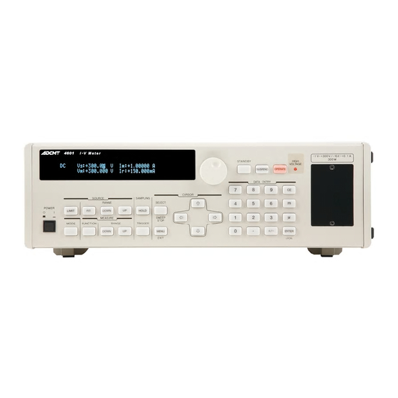
4601 I-V Meter Operation Manual 2.1.1 Display Section 2.1.1 Display Section The screen employs a dot matrix vacuum fluorescent display. Figure 2-2 Display Section Display Displays the source value, the voltage measured value, the current measured value, the reference current measured value and the unit operational status. -
Page 43: 2.1.3 Mode Section
4601 I-V Meter Operation Manual 2.1.3 MODE Section 2.1.3 MODE Section Figure 2-4 MODE Section MODE key Switches between the DC source mode and the sweep source mode. 2.1.4 MEASURE Section This section is used to switch the measurement function and the range displayed in the lower right on the screen in the DC source mode. -
Page 44: Sampling Section
4601 I-V Meter Operation Manual 2.1.5 SAMPLING Section 2.1.5 SAMPLING Section This section is used to set the sampling in the DC source mode or sweep source mode. Figure 2-6 SAMPLING Section HOLD key Switches the sampling between AUTO and HOLD. -
Page 45: Cursor Section
4601 I-V Meter Operation Manual 2.1.6 CURSOR Section 2.1.6 CURSOR Section This section is used to select the digit or change the value when changing the voltage source value, current limit value or setting value in the menu. 1, 2... -
Page 46: Data Entry Section
4601 I-V Meter Operation Manual 2.1.7 DATA ENTRY Section 2.1.7 DATA ENTRY Section The DATA ENTRY keys are used to change the voltage source value, the current limit value and the parameters to be input. 7, 8 Figure 2-8 DATA ENTRY Section 0 to 9 keys Enters numeric data from 0 to 9. -
Page 47: Operate Section
4601 I-V Meter Operation Manual 2.1.8 OPERATE Section 2.1.8 OPERATE Section Sets the output ON or OFF. Figure 2-9 OPERATE Section STANDBY key Sets the output status to Standby (output unit relay OFF). SUSPEND key Sets the output status to Suspend (output unit relay ON, voltage source: 0V and high-impedance). -
Page 48: Front Output Unit Section
4601 I-V Meter Operation Manual 2.1.9 Front Output Unit Section 2.1.9 Front Output Unit Section The following is an example when the safety socket terminal output unit is installed on the front. Figure 2-10 Front Output Unit Section (for Safety Socket) -
Page 49: Power Switch
4601 I-V Meter Operation Manual 2.1.10 POWER Switch 2.1.10 POWER Switch Figure 2-11 POWER Switch POWER switch: Turns the power ON or OFF. Screen Display (Annotations) This section describes the screen display (annotations). Display in the DC mode Display in the sweep mode... - Page 50 4601 I-V Meter Operation Manual 2.2 Screen Display (Annotations) Vs: Voltage source value Im: Current measured value (ADC2 measurement) Vm: Voltage measured value (ADC1 measurement) ADC3 measurement Reference cell current measurement External voltage measurement Ch1 T-type thermocouple measurement Ch1 resistance bulb (Pt) temperature measurement...
-
Page 51: Rear Panel
4601 I-V Meter Operation Manual 2.3 Rear Panel Rear Panel 14 15 Figure 2-13 Rear Panel Rear output terminal Shows that output unit (safety socket output terminal unit) is mounted on the rear. Ground terminal PE Protective ground terminal Reference cell connection terminal CELL Ir Receptacle for the 4-pin cannon plug to connect the reference cell (Refer to Section 5.1.2, "Reference Cell... - Page 52 4601 I-V Meter Operation Manual 2.3 Rear Panel GPIB connector Used to remotely control the 4601 by GPIB. Temperature measurement connector Tc1, Pt1, Ad1 5-pin connector for Ch1 to connect the miniature thermocouple socket that connects the T-type thermocouple, the PT sensor and IC sensor (AD590) (Refer to 5.1.4, "Temperature Measurement Terminal")
-
Page 53: Basic Operations
4601 I-V Meter Operation Manual 3. BASIC OPERATIONS BASIC OPERATIONS This chapter describes how to operate the 4601 using examples. NOTE: The operation procedures listed permit the settings to be made in the shortest time. If the display differs from the one shown, repeat the procedure from the beginning. -
Page 54: Power On
4601 I-V Meter Operation Manual 3.1 Power ON Power ON Turn On the 4601 according to the following procedure: Ensure that the voltage of the used power supply matches the power voltage display on the rear panel. Then, connect the supplied power cable CAUTION: To prevent damage to the 4601, do not apply a voltage or frequency that exceeds the specified range. -
Page 55: Dc Source Mode
4601 I-V Meter Operation Manual 3.2 DC Source Mode DC Source Mode 3.2.1 Setting and Outputting Voltage Source Value Setting the voltage source value using the numeric keypad This section describes the procedure of setting the source value using the numeric keypad and out- putting it. - Page 56 4601 I-V Meter Operation Manual 3.2.1 Setting and Outputting Voltage Source Value Example display Press again to stop the output (Standby). The OPERATE key goes OFF. Setting the voltage source value using the rotary knob (for fixed range) This section describes the procedure of setting the source value using the rotary knob and outputting Each procedure should be started with the initial state (factory default settings).
- Page 57 4601 I-V Meter Operation Manual 3.2.1 Setting and Outputting Voltage Source Value Press three times to move the cursor onto the tenth digit. Example display Set to 10 V by rotating the rotary knob. Example display Press to output the source value (Operate). While the source value is output, the OPERATE key lights up.
-
Page 58: Setting Current Limits
4601 I-V Meter Operation Manual 3.2.2 Setting Current Limits 3.2.2 Setting Current Limits Both positive and negative current limits can be set on the 4601 to prevent the 4601 and the devices from overcurrent. Setting the current limits Set the current limit values to 1 A, and +0.1 A and -2 A according to the following procedure:... - Page 59 4601 I-V Meter Operation Manual 3.2.2 Setting Current Limits Press . Select 3) Limit Input from A) SOURCE with , and change from ±Balanced to Individual with the rotary knob. Then, press to exit the menu screen. Press to switch to the limit setting screen.
- Page 60 4601 I-V Meter Operation Manual 3.2.2 Setting Current Limits Setting ranges of current limits(for optimal range) The following table shows the setting ranges of current limits. Current of +0.1 A or higher can be set but cannot be output without a booster.
-
Page 61: 3.2.3 Changing Measurement Function And Range
4601 I-V Meter Operation Manual 3.2.3 Changing Measurement Function and Range 3.2.3 Changing Measurement Function and Range As the 4601 includes three AD converters (ADC1 to ADC3), it can measure three points simultaneously. The three measurement points are shown below, and among which ADC3 has eight measurement functions. - Page 62 4601 I-V Meter Operation Manual 3.2.3 Changing Measurement Function and Range Changing the measurement function Operating procedure Example display Pressing the FUNCTION key changes the measurement function display on the lower right. Example display Every pressing the FUNCTION key switches the function as shown on the right.
- Page 63 4601 I-V Meter Operation Manual 3.2.3 Changing Measurement Function and Range Changing the measurement range Operating procedure Example display When the reference cell current measurement or external voltage measurement function is selected, pressing on the MEASURE section lowers the range by one and pressing raises it by one.
-
Page 64: Sweep Source Mode
4601 I-V Meter Operation Manual 3.3 Sweep Source Mode Sweep Source Mode Solar cell I-V characteristic measurement sweeps the source voltage in the sweep source mode, measures voltage and current at each step, and displays the data graphically. The data is converted into a graph on an external computer via the GPIB or USB interface. -
Page 65: Checking Measured Values
4601 I-V Meter Operation Manual 3.3.2 Checking Measured Values Example display When sweep ends, RUN disappears and the screen returns to the display before start. The measured data is stored in the measurement memory. For more information, refer to Section 5.3.7, "Measure- ment Data Memory."... -
Page 66: Setting Current Limits
4601 I-V Meter Operation Manual 3.3.3 Setting Current Limits 3.3.3 Setting Current Limits The procedure of setting the current limits is the same as the procedure described in Section 3.2.2, “Setting Current Limits.” 3.3.4 Changing Reference Cell Current Range In the sweep source mode, the ADC3 measurement function is fixed to the reference cell current measurement function Ir. - Page 67 4601 I-V Meter Operation Manual 3.3.5 Setting Memory Sweep Data Select 3) Memory Data Set from C) SWEEP VALUE with Example display Press to move to the lower level. Example display Set the source value with , and or by using the rotary knob.
- Page 68 4601 I-V Meter Operation Manual 3.3.5 Setting Memory Sweep Data Press the SELECT key, and repeat Step to set necessary source data. Select 4) Mem. Save/Clear with , and Example display Press Example display Press to save the setting values to the non-volatile memory.
-
Page 69: 3.4 Menu Operation
4601 I-V Meter Operation Manual 3.4 Menu Operation Menu Operation The 4601 functions and parameters are set on a hierarchical menu. This section describes the menu structure and the procedures of operating the menu. 3.4.1 Menu Structure The menu is a 3-level hierarchical structure. - Page 70 4601 I-V Meter Operation Manual 3.4.1 Menu Structure 3-18...
-
Page 71: How To Operate Menu
4601 I-V Meter Operation Manual 3.4.2 How to Operate Menu * 1: Use or the rotary knob to select the categories. * 2: Use to move from the Category level to the Select level. * 3: Use or the rotary knob to select the parameters at the Select level. - Page 72 4601 I-V Meter Operation Manual 3.4.2 How to Operate Menu Select the parameter items at Select level with or by using the rotary knob. Example display Move from the Select level to the Input/Run level with Example display Current category...
-
Page 73: Initializing Setting Conditions
4601 I-V Meter Operation Manual 3.5 Initializing Setting Conditions Initializing Setting Conditions This section describes the procedure of initializing the setting conditions (parameters) of the 4601. There are the following two types of initialization by key operations: • Initializing the parameters from the menu •... -
Page 74: Restoring To Factory Default Settings
4601 I-V Meter Operation Manual 3.5.2 Restoring to Factory Default Settings Press to load the default values. Example display Press to exit the menu. 3.5.2 Restoring to Factory Default Settings Operating procedure Turn OFF the power. Turn ON the power while pressing at the same time. -
Page 75: Saving And Loading Parameters
4601 I-V Meter Operation Manual 3.6 Saving and Loading Parameters Saving and Loading Parameters The 4601 can save setting parameters to and load them from the non-volatile memory, areas User-0 to User-3. The 4601 has a program memory data area, separated from the parameter save area. -
Page 76: Saving Parameters
4601 I-V Meter Operation Manual 3.6.2 Saving Parameters Press or rotate the rotary knob to select User-1. Example display Press to load the parameters from User-1. Example display The descriptions of these parameters are as follows: User-0 Loads the parameters from User-0. - Page 77 4601 I-V Meter Operation Manual 3.6.2 Saving Parameters Press to move to the lower level. Example display Press or rotate the rotary knob to select Save. Example display Press to move to the lower level. Example display Press or rotate the rotary knob to select User-3.
-
Page 78: Auto Parameter Loading At Power On
4601 I-V Meter Operation Manual 3.6.3 Auto Parameter Loading at Power ON 3.6.3 Auto Parameter Loading at Power ON The 4601 memorizes the settings at power OFF and starts up with the same settings at next power ON. To start up using predefined parameters, parameters saved in User-0 can be loaded at startup. - Page 79 4601 I-V Meter Operation Manual 3.6.3 Auto Parameter Loading at Power ON Press or rotate to select User-0 Saved. Example display Press to exit the menu. 3-27...
-
Page 81: Menu Index
4601 I-V Meter Operation Manual 4. FUNCTIONAL REFERENCE FUNCTIONAL REFERENCE This chapter describes panel keys, parameter groups (categories), parameter items and parameter functions in the following sections: • 4.1 Menu Index: Use this section as an index for the parameters in the menu. - Page 82 4601 I-V Meter Operation Manual 4.1 Menu Index Sweep Type..........4-5 SWEEP VALUE........4-6 SYSTEM..........4-10 Temp. Unit ..........4-7 Third Value ..........4-6 TIME............4-7 Trigger Delay ........... 4-7 USB Id ............. 4-9...
-
Page 83: Panel Key Descriptions
4601 I-V Meter Operation Manual 4.2 Panel Key Descriptions Panel Key Descriptions This section describes the function of the panel keys and the parameters in the menu in alphabetical order. 4.2.1 CURSOR Key (Cursor Moving) keys Moves the cursor (highlight) that indicates a digit of the source value to the right or left. -
Page 84: Exit Key (Menu Setting Cancellation)
4601 I-V Meter Operation Manual 4.2.5 EXIT Key (Menu Setting Cancellation) 4.2.5 EXIT Key (Menu Setting Cancellation) Exits the menu screen to return to the source value screen. (The MENU key goes OFF.) 4.2.6 FIT Key (Optimal Voltage Source or Current Limit Range) Selects the optimal range for voltage source or current limit automatically. -
Page 85: Menu Key (Parameter Setting)
4601 I-V Meter Operation Manual 4.2.10 MENU Key (Parameter Setting) 4.2.10 MENU Key (Parameter Setting) Switches to the menu screen to set the parameter groups (categories). Goes ON during menu screen display. For information on how to set the parameters using the menu, refer to Section 3.4, "Menu Operation."... - Page 86 4601 I-V Meter Operation Manual 4.2.10 MENU Key (Parameter Setting) 3) Reverse Switches reverse sweep ON or OFF. Off: One-way sweep Round sweep 4) Return to Bias Selects whether sweep stops at the bias value or stop value. Off: Stop value...
- Page 87 4601 I-V Meter Operation Manual 4.2.10 MENU Key (Parameter Setting) Fixed level sweep: 1) Bias Value Sets the bias value. 2) Level Value Sets the level value. 3) Sample Count Sets the sampling count. Memory sweep: 1) Bias Value Sets the bias value.
- Page 88 4601 I-V Meter Operation Manual 4.2.10 MENU Key (Parameter Setting) F) EXT.SIGNAL Sets the external signal-related parameters. 1) Operate Control Selects the signal for the BNC connector OPERATE IN/OUT on the rear panel. Standby In Sets Standby when the signal level changes from LO to HI.
- Page 89 4601 I-V Meter Operation Manual 4.2.10 MENU Key (Parameter Setting) 3) Load @ PWR On Selects the setting parameter condition at power ON. Saved @ PWR Off Start up using the parameters saved when the power was last turned off.
-
Page 90: Mode Key (Source Mode Selection)
4601 I-V Meter Operation Manual 4.2.11 MODE Key (Source Mode Selection) J) SYSTEM Sets the system-related parameters. 1) Display On/Off Turns ON or OFF the screen. Turns ON the screen. OFF in Remote: Turns OFF the screen only in remote control. -
Page 91: Standby Key (Output Off)
4601 I-V Meter Operation Manual 4.2.14 STANDBY Key (Output OFF) 4.2.14 STANDBY Key (Output OFF) Sets the voltage output status to Standby (output unit relay OFF). 4.2.15 SUSPEND Key (Output OFF) Sets the voltage output status to Suspend. Suspend status: While the output unit relay is set to ON, the voltage source value is 0 V and the current limit is set to the setting value or minimum value in the setting range. -
Page 93: Operational Descriptions
4601 I-V Meter Operation Manual 5. OPERATIONAL DESCRIPTIONS OPERATIONAL DESCRIPTIONS Connection of Sample For the connections to solar cells to be tested and sensors, see Figure 1-1. 5.1.1 Connection with Output Unit The output terminal unit can be mounted on either the front or rear panel. -
Page 94: Reference Cell Measurement Terminal
4601 I-V Meter Operation Manual 5.1.2 Reference Cell Measurement Terminal Twist pair cables are connected to HI OUTPUT and LO OUTPUT and to HI SENSE and LO SENSE in pairs respectively. The wire size is determined depending on the current value used on the OUTPUT side. -
Page 95: External Voltage Measurement Terminal
4601 I-V Meter Operation Manual 5.1.3 External Voltage Measurement Terminal 5.1.3 External Voltage Measurement Terminal The following figure shows the terminal to measure voltage. Applicable plug: Product equivalent to Multi-Contact safety plug 4 Applicable cable: Cable A01044 Alligator clip adapter A08532 Figure 5-4 External Voltage Measurement Terminal 5.1.4... - Page 96 4601 I-V Meter Operation Manual 5.2 Source Mode Source Mode This section describes the basic operations and timing of the DC source mode and the sweep source mode. The 4601 has two source modes: the sweep source mode that allows easy acquisition of PV I-V characteristic curves, and the DC source mode that allows checking of system connections or device operations.
-
Page 97: Dc Source Mode
4601 I-V Meter Operation Manual 5.2.1 DC Source Mode 5.2.1 DC Source Mode The following table shows the operational descriptions of the DC source mode. Table 5-2 Operations in DC Source Mode (1 of 2) Operational Sampling Description Operation Remarks... - Page 98 4601 I-V Meter Operation Manual 5.2.1 DC Source Mode Table 5-2 Operations in DC Source Mode (2 of 2) Operational Sampling Description Operation Remarks condition Changing the AUTO Source value Tp: Period time source value changing Td: Measurement induces range delay time changing.
-
Page 99: Sweep Source Mode
4601 I-V Meter Operation Manual 5.2.2 Sweep Source Mode 5.2.2 Sweep Source Mode There are the following types of the sweep source mode: linear sweep for simple source measurement, 2- slope linear sweep and 3-slope linear sweep that allow fine-step source measurement at necessary points, fixed level sweep that sweeps a constant value the specified number of sample count, and memory sweep that sweeps arbitrary values stored in the memory from the start address to the stop address. - Page 100 4601 I-V Meter Operation Manual 5.2.2 Sweep Source Mode Table 5-3 Operational Descriptions of Sweep Source Mode (2 of 2) Sweep type Operational description Waveform Fixed level sweep Sweeps the specified constant value the fSWP specified number of sample count.
-
Page 101: Source Measurement Operations In Sweep Source Mode
4601 I-V Meter Operation Manual 5.2.2 Sweep Source Mode The following table shows the source and measurement timings in the sweep source mode with reverse OFF (one-way sweep). Table 5-4 Source Measurement Operations in Sweep Source Mode Operational Sampling Description... -
Page 102: Reverse Function
4601 I-V Meter Operation Manual 5.2.3 Reverse Function 5.2.3 Reverse Function Turning ON or OFF the reverse function switches the sweep operation between one-way sweep and round sweep. Reverse OFF: One-way sweep Reverse ON: Round sweep The sweep operation of the linear sweep is described below. -
Page 103: Output At Sweep End
4601 I-V Meter Operation Manual 5.2.4 Output at Sweep End 5.2.4 Output at Sweep End The output value at the sweep end can be switched by setting RTB. Return to Bias Waveform Description Returns to the bias Stop value value at the sweep end. -
Page 104: Restrictions On Time Parameters
4601 I-V Meter Operation Manual 5.2.5 Source and Measurement Timings 5.2.5.2 Restrictions on Time Parameters The time parameters impose setting restrictions on each other. If any restriction is ignored in setting, an error message appears in the Operate or Suspend status. - Page 105 4601 I-V Meter Operation Manual 5.2.5 Source and Measurement Timings Period time (Tp)200 s • Condition) Source mode: Sweep mode Sampling: HOLD • Measurement delay time (Td) + Integration time (Tit) + AD processing time (Tk) < Period time (Tp)
- Page 106 4601 I-V Meter Operation Manual 5.2.5 Source and Measurement Timings Relation between setting restrictions and source modes The following table shows the setting restrictions to be checked according to the source mode. Source mode/Sampling Setting restriction SWP/AUTO SWP/HOLD [(Td+300 s) < Tp] [10 ms Tp]...
-
Page 107: 5.2.6 Settling Time
4601 I-V Meter Operation Manual 5.2.6 Settling Time 5.2.6 Settling Time The settling time for voltage source varies depending on the response switching. The stability of output voltage or current varies depending on the cable inductance or device capacitance. Also, the slower the response is, the more the output voltage or current is stabilized. - Page 108 4601 I-V Meter Operation Manual 5.2.6 Settling Time Condition: When the response is fast or Ext.fast, Sr and p used in the settling time formula vary depending on the source voltage change Vs and its maximum value Vs max as follows.
- Page 109 4601 I-V Meter Operation Manual 5.2.6 Settling Time Example 1) Voltage source range: 5 V, current limit range: 3 A, current limit value: 100 mA, response: Ext.fast As the current limit count value D is 100, Vs max=0.024 100=2.4[V].
-
Page 110: Source Measurement Function
4601 I-V Meter Operation Manual 5.3 Source Measurement Function Source Measurement Function 5.3.1 Source Range When the optimal range for voltage source is selected (the FIT key goes ON) in the DC source mode, the range is determined according to the following list:... - Page 111 4601 I-V Meter Operation Manual 5.3.2 Suspend Function Operation Standby status Pressing STANDBY sets the output status to Standby. The 4601 is securely isolated from the DUT. HiZ Suspended status Pressing SUSPEND sets the output status to Suspend. The SUSPEND key goes ON.
- Page 112 4601 I-V Meter Operation Manual 5.3.2 Suspend Function Sweep source Operate status OPERATE Power ON Sweep start Standby status Bias output status Sweep status STANDBY OPERATE Sweep stop SUSPEND SUSPEND STANDBY , SUSPEND OPERATE Suspend status NOTE: The source data during sweeping is generated with the following timing.
- Page 113 4601 I-V Meter Operation Manual 5.3.2 Suspend Function Effective operations in each status are described below. Status Effective operation Operate Measurement Suspend Device replacement Measurement stop. The output status is as follows: Sweep mode: 0 V in the bias range...
-
Page 114: High Voltage Indicator Lightning Condition
4601 I-V Meter Operation Manual 5.3.3 High Voltage Indicator Lightning Condition 5.3.3 High Voltage Indicator Lightning Condition When the 4601 generates 55 V or higher or its source condition is set, the High Voltage indicator goes ON. DC mode Sweep mode... - Page 115 4601 I-V Meter Operation Manual 5.3.5 Spot Measurement 5.3.5 Spot Measurement The spot measurement operates only in remote control (GPIB/USB) and not by using the keys. This function returns measured data when recognizing specified commands regardless of the source mode and Operate/Suspend/Standby.
-
Page 116: 5.3.6 Zero Measurement
4601 I-V Meter Operation Manual 5.3.6 Zero Measurement 5.3.6 Zero Measurement Zero measurement is a function that measures analog common voltage and cancels the offset errors of the AD converters automatically. Execute zero measurement once after warm-up. Types of zero measurement... -
Page 117: Measurement Data Memory
4601 I-V Meter Operation Manual 5.3.7 Measurement Data Memory 5.3.7 Measurement Data Memory The measurement data memory can store up to 4000 data for each measurement types: ADC1, ADC2 and ADC3 (in the DC mode, or in the sweep mode with reverse ON). When the memory runs out, memory storing stops and the MFL bit of the status register is set to ON. -
Page 118: Alarm Detection
4601 I-V Meter Operation Manual 5.4 Alarm Detection Specify the memory address to call the measured value at each step by using the rotary knob or numeric keypad. Example display Press The MENU key goes OFF and the memory read status is complete. -
Page 119: Relay Life Cycle Detection
4601 I-V Meter Operation Manual 5.4.3 Relay Life Cycle Detection 5.4.3 Relay Life Cycle Detection The 4601 stores the relay ON/OFF operations of the output unit, and generates an alarm when the relay life cycle is reached. Every time the output relay in the output unit is switched, the relay counter value increments. If the value has reached 1,000,000 times or more when the self test is executed or the output status is set to Standby, an error is displayed. - Page 120 4601 I-V Meter Operation Manual 5.4.3 Relay Life Cycle Detection Operating procedure Press to select 1) MAINTENANCE from the categories and 6) Reset Counter from the parameter items. Example display Press to move to the lower level. Example display Press to reset the relay counter.
-
Page 121: 5.4.4 Other Alarm Detection
4601 I-V Meter Operation Manual 5.4.4 Other Alarm Detection 5.4.4 Other Alarm Detection Other alarms are detected in the event of occurrence of abnormalities such as overvoltage or fan stop. When any of these alarms is detected, the output turns OFF and is set to the Standby status. -
Page 122: Rear Input And Output Signal
4601 I-V Meter Operation Manual 5.5 Rear Input and Output Signal Rear Input and Output Signal 5.5.1 Contact Signal Input and Output Optical semiconductor relay contact signals can be output arbitrarily to the contact input and output termi- nal (CONTACT IN/OUT), and the contact signal input ports can be read out. - Page 123 4601 I-V Meter Operation Manual 5.5.1 Contact Signal Input and Output Contact signal Input and Output Pins Pin No. Signal name Input/output Target Remarks DGOUT1+ Output Output port 1 Optical semiconductor relay contact output DGOUT1- DGOUT2+ Output Output port 2...
-
Page 124: External Control Signals
4601 I-V Meter Operation Manual 5.5.2 External Control Signals Solar Simulator Operation Example Make Shutter opening and closing Break (Output port 1) Break? Shutter response Make? (Input port 1) Make Pulse emission Break (Output port 2) Sweep start I-V measurement... -
Page 125: Restrictions On Using External Trigger
4601 I-V Meter Operation Manual 5.5.3 Restrictions on Using External Trigger 5.5.3 Restrictions on Using External Trigger This section describes restrictions on using the external trigger (TRIGGER IN signal). The TRIGGER IN signal controls the source and measurement timings to synchronize with the external devices such as slave channel in the synchronized operation. -
Page 126: Restriction On Top
4601 I-V Meter Operation Manual 5.5.3 Restrictions on Using External Trigger Table 5-10 Restriction on Top Status before Operate Standby 120 ms*1 Suspend 60 ms 10 ms Period time Hold time Tp (ext): TRIGGER IN signal period Th (ext): TRIGGER IN signal hold time (Time between sweep start trigger and start value genera-... - Page 127 4601 I-V Meter Operation Manual 5.5.3 Restrictions on Using External Trigger • Example in the DC source mode • Example in the sweep source mode 5-35...
-
Page 128: Operating Multiple 4601
4601 I-V Meter Operation Manual 5.6 Operating Multiple 4601 Operating Multiple 4601 This section describes synchronous operation, series connection, and parallel connection using more than one 4601. 5.6.1 Synchronous Operation The synchronous operation of multiple 4601 units allows synchronization of measurement timing in the DC source mode, and both source and measurement timings in the sweep source mode. - Page 129 4601 I-V Meter Operation Manual 5.6.1 Synchronous Operation 5-37...
- Page 130 4601 I-V Meter Operation Manual 5.6.1 Synchronous Operation Restriction on Setting The 4601 has a Tsync (approx. 25 s) time delay from the external trigger input to the measure- • ment start. Set this time delay according to the following formula 1. when using more than one 4601 in synchronous operation.
-
Page 131: Parallel Connection
4601 I-V Meter Operation Manual 5.6.2 Parallel Connection 5.6.2 Parallel Connection Two 4601 units connected in parallel are capable of sink operation up to +30 V/-20 A. The following shows a connection diagram in which two units are connected in parallel using a 4-wire con- nection. -
Page 132: Series Connection
4601 I-V Meter Operation Manual 5.6.3 Series Connection 5.6.3 Series Connection Two 4601 units connected in series are capable of sink operation up to +600 V/-1 A. The output voltage is the total of No.1 output voltage (HI side) and No2. output voltage (LO side). - Page 133 4601 I-V Meter Operation Manual 5.6.3 Series Connection Example) Operate/Standby procedure when the PV output voltage is 500 V <Operate procedure> No.2 setting voltage 500 V - 300 V (= 200 V) No.1 setting voltage = 0 V Set No.2 to Operate.
-
Page 134: Series Connection
4601 I-V Meter Operation Manual 5.6.3 Series Connection Figure 5-13 Series Connection CAUTION: If the load is short-circuited, reverse polarity voltage is applied to the 4601 themselves. Depending on the set- tings, an overload may be generated when the short-circuit occurs. -
Page 135: Serial Sweep
4601 I-V Meter Operation Manual 5.6.4 Serial Sweep 5.6.4 Serial Sweep This section describes an example where one of two 4601 units connected in series finishes sweep and then the other starts sweep. Two 4601 units in series connected are capable of sink operation up to +600 V /-1 A. - Page 136 4601 I-V Meter Operation Manual 5.6.4 Serial Sweep The output voltage is the total of No.1 output voltage (HI side) and No2. output voltage (LO side). Set the current limit values under the following conditions: No.1 current limit value < No.2 current limit value When setting the limit values to 10 A, set as follows: No.1 limit value = 10 A...
-
Page 137: Serial Sweep Output Example And Connection Method
4601 I-V Meter Operation Manual 5.6.4 Serial Sweep Figure 5-14 Serial Sweep Output Example and Connection Method CAUTION: If the load is short-circuited, reverse polarity voltage is applied to the 4601 themselves. Depending on the set- tings, an overload may be generated when the short-circuit occurs. -
Page 138: Self Test
4601 I-V Meter Operation Manual 5.7 Self Test Self Test The 4601 tests itself when the power is turned ON or the execution is requested by the command TST? or key operation. The following table shows the self test descriptions, error codes and error messages. - Page 139 4601 I-V Meter Operation Manual 5.7 Self Test Table 5-12 Self Test Items (2 of 3) Executing method Error Description Message Power code *TST? operation +135 ADC3 operation IR5-IR6 ratio ADC3 Ratio 5 to 6 +141 ADC1 operation ZERO measurement...
- Page 140 4601 I-V Meter Operation Manual 5.7 Self Test Table 5-12 Self Test Items (3 of 3) Executing method Error Description Message Power code *TST? operation +015 No output unit mounted No Output unit -313 Calibration data Calibration memory lost +130 Sub CPU communication...
-
Page 141: Error Log
4601 I-V Meter Operation Manual 5.8 Error Log Error Log The 4601 holds the error number in the error log memory when it detects an error. Operation A maximum of twenty memory areas are available for the error log and they operate as follows: •... - Page 142 4601 I-V Meter Operation Manual 5.8 Error Log Press Rotate the rotary knob or press to change the error log number and read error descriptions. The following is an example of "Undefined header." Example display 5-50...
-
Page 143: Operational Principles
4601 I-V Meter Operation Manual 5.9 Operational Principles Operational Principles 5.9.1 Block Diagram HiLmt HiLimit HI SENSE HI OUTPUT LoLimit LoLmt LO SENSE LO OUTPUT ADC1 ADC2 5-51... -
Page 144: Voltage Source/Voltage Measurement/Current Measurement Terminal Circuit
4601 I-V Meter Operation Manual 5.9.2 Operational Principles 5.9.2 Operational Principles 5.9.2.1 Voltage Source/Voltage Measurement/Current Measurement Terminal Circuit • The voltage source/voltage measurement/current measurement circuit of the 4601 contains a DA converter SrcDAC for setting the voltage source. This circuit also has two DA converters for setting the current limits: HiLimitDAC and LoLimitDAC. -
Page 145: Adc3 Measurement Circuit
4601 I-V Meter Operation Manual 5.9.2 Operational Principles 5.9.2.2 ADC3 Measurement Circuit • The ADC3 measurement circuit can switch between eight functions: Ir, Em, Tc1, Pt1, Ad1, Tc2, Pt2 and Ad2 in the DC source mode or spot measurement. In the sweep source mode, only Ir is selected and measured simultaneously with Vm and Im. -
Page 147: Remote Programming
4601 I-V Meter Operation Manual 6. REMOTE PROGRAMMING REMOTE PROGRAMMING Using Interface The 4601 offers GPIB and USB interfaces. They cannot be used at the same time. Select which interface you wish to use. 6.1.1 Selecting Interface The interface can only be selected from the front panel menu. -
Page 148: Gpib
4601 I-V Meter Operation Manual 6.2 GPIB GPIB 6.2.1 Overview GPIB (General Purpose Interface Bus) allows external control of the 4601 measurement function settings, measurement parameter settings, and reading measurement data, making it simple to configure an auto- mated measurement system. -
Page 149: Precautions When Using Gpib
4601 I-V Meter Operation Manual 6.2.2 Precautions when Using GPIB 6.2.2 Precautions when Using GPIB Do not use too long a connection cable or bus cable to connect any instrument or controller. Ensure that the total cable length does not exceed 20 m. ADC CORPORATION offers the following standard bus cables. -
Page 150: Setting Gpib
4601 I-V Meter Operation Manual 6.2.3 Setting GPIB 6.2.3 Setting GPIB This section describes the procedure of changing the GPIB address and the output format. Changing the GPIB address from 01 to 12 Changing the output format from ASCII to binary... - Page 151 4601 I-V Meter Operation Manual 6.2.3 Setting GPIB Press to select the digit and rotate the rotary knob to change the value. Or directly input the address by using the numeric keypad. Example display Press to move to the upper level.
-
Page 152: Usb
4601 I-V Meter Operation Manual 6.3 USB 6.3.1 Overview The 4601 is USB (Universal Serial Bus) equipped conforming to USB 2.0 standard. USB allows function settings and reading of measurement data with respect to multiple instruments con- nected to the bus using a PC, making it simple to configure an automated measurement system. -
Page 153: Setting Usb Id
4601 I-V Meter Operation Manual 6.3.5 Setting USB ID 6.3.5 Setting USB ID This section describes the procedure of setting the USB ID address. Changing the USB ID address from 01 to 12 Operating procedure Press . The MENU key goes ON. - Page 154 4601 I-V Meter Operation Manual 6.3.5 Setting USB ID Press to move to the upper level, and press or rotate the rotary knob to select 2) USB Id. Example display Press to move to the lower level. Example display Press to select the digit and rotate the rotary knob to change the value.
-
Page 155: Status Register Structure
4601 I-V Meter Operation Manual 6.4 Status Register Structure Status Register Structure The 4601 has a hierarchical status register structure that conforms to the IEEE standard 488.2-1987 and can send various statuses of the 4601 to the controller. This section describes the operation model of the status structure and the allocation of events. -
Page 156: Status Byte Register
4601 I-V Meter Operation Manual 6.4 Status Register Structure The 4601 has the following four types of status registers: • Status Byte Register (STB) • Standard Event Status Register (SESR) • Questionable Event Register (QSR) • Measurement Event Register (MER) -
Page 157: Status Register Structure
4601 I-V Meter Operation Manual 6.4 Status Register Structure • Common conditions in which the Status Byte Register is cleared All cleared when the power is turned ON. All cleared by *CLS except that MAV is not cleared if data exists in the output buffer. -
Page 158: Standard Event Status Register
4601 I-V Meter Operation Manual 6.4 Status Register Structure Standard Event Status Register (SESR) Table 6-4 Standard Event Status Register Name Description ON: Set to 1 when all operations are complete after receiving the (Operation Complete) *OPC command. Not in use... - Page 159 4601 I-V Meter Operation Manual 6.4 Status Register Structure Measurement Event Register (MER) Table 6-5 Measurement Event Register Name Description 0 OVL ON: Set to 1 when overload is detected (Overload) 1 FAN ON: Set to 1 when fan stop is detected.
- Page 160 4601 I-V Meter Operation Manual 6.4 Status Register Structure Questionable Event Register (QSR) Table 6-6 Questionable Event Register Name Description 0 Not in use Always set to 0 1 MRO ON: Set to 0 when a measurement over-range occurs. (Measurement Range Over)
-
Page 161: Data Output Format
4601 I-V Meter Operation Manual 6.5 Data Output Format Data Output Format 6.5.1 Measured Value Output The 4601 outputs data in the order of ADC1 measured value, ADC2 measured value and ADC3 measured value. When data of multiple measurement memories is output, this order is repeated. ( ...) -
Page 162: Output Format Selection
4601 I-V Meter Operation Manual 6.5.3 Output Format Selection 6.5.3 Output Format Selection Either of the following two output formats of the measured values can be selected before measurement starts (DC mode) or before measurement memory data is output (sweep mode). - Page 163 4601 I-V Meter Operation Manual 6.5.4 ASCII Output Format Header Whether headers are output or not can be set by using the command or from the MENU. Function Target Main header (ADC1) (ADC2) (ADC3) (Reference cell Isc) (EXT.DCV) Ch1 thermocouple T...
- Page 164 4601 I-V Meter Operation Manual 6.5.4 ASCII Output Format Mantissa part and exponent part Measurement function Mantissa part Exponent part Range/mode d.ddddd ADC1 E+00 dd.dddd 50 V E+00 ddd.ddd 300 V E+00 300 A ddd.ddd ADC2 E-06 d.ddddd 3 mA E-03 dd.dddd...
- Page 165 4601 I-V Meter Operation Manual 6.5.4 ASCII Output Format Block delimiter The block delimiters can be specified by using the following commands: Block delimiter Setting command CR LF+EOI LF+EOI NOTE: When the binary output format is selected, “EOI” is specified regardless of the block delimiter settings.
-
Page 166: Binary Output Format
4601 I-V Meter Operation Manual 6.5.5 Binary Output Format 6.5.5 Binary Output Format When the binary output format is selected, DC measurement data and measurement data in the measure- ment memories are output in IEEE 488.2 “Definite Length Block Response Data Format.”... - Page 167 4601 I-V Meter Operation Manual 6.5.5 Binary Output Format Definite Length Block Response Data Format # n m • • • m ddddddd • • • dddddddd data Specifies how many data bytes will follow. Specifies how many digits are contained.
-
Page 168: Remote Commands
4601 I-V Meter Operation Manual 6.6 Remote Commands Remote Commands 6.6.1 Command Syntax The command syntax is defined by the following format. Space Space Space Header Data (blank character) (blank character) (blank character) Header There are two types of headers: common command headers and simple headers. The common com- mand header has an asterisk mark (*) placed in front of the mnemonic. -
Page 169: Data Format
4601 I-V Meter Operation Manual 6.6.2 Data Format 6.6.2 Data Format The 4601 uses the following data types for data input and output. Numeric data There are three numeric data formats, any of which can be used for input. Some commands can add units to the data when the data is input. -
Page 170: Remote Command List
4601 I-V Meter Operation Manual 6.6.3 Remote Command List 6.6.3 Remote Command List The Default column shows default settings at Power ON or at factory shipment. • The Power ON column shows the status when the power is turned ON. - Page 171 4601 I-V Meter Operation Manual 6.6.3 Remote Command List Default Operation During Item Command Description Power Factory Sweep calibration shipment OPR/SUS OPR/SUS Source Source mode DC mode DC sweep mode Response: MD0 to MD1 Source range SVRX Optimal range SVR4...
- Page 172 4601 I-V Meter Operation Manual 6.6.3 Remote Command List Default Operation During Item Command Description Power Factory Sweep calibration shipment OPR/SUS OPR/SUS Source Operate/ Sets the output to OFF (Standby). standby Sets the output to ON (Operate). Sets the output to Suspend (Suspend).
- Page 173 4601 I-V Meter Operation Manual 6.6.3 Remote Command List Default Operation During Item Command Description Power Factory Sweep calibration shipment OPR/SUS OPR/SUS [fd, sd, Sweep 2-slope linear First value (-1 mV) ld, st1, st2] sweep Second value (0 V) Last value (2 mV) Step 1 count (1 to 1999) st1+st2 ...
- Page 174 4601 I-V Meter Operation Manual 6.6.3 Remote Command List Default Operation During Item Command Description Power Factory Sweep calibration shipment OPR/SUS OPR/SUS sweep Memory sweep [adr] Sweep memory data setting starts from N command and com- source data pletes at P command.
- Page 175 4601 I-V Meter Operation Manual 6.6.3 Remote Command List Default Operation During Item Command Description Power Factory Sweep calibration shipment OPR/SUS OPR/SUS 5 s Mea- Integration time sure- 10 s ment 25 s 50 s 100 s 250 s 500 s 1 ms 2.5 ms...
- Page 176 4601 I-V Meter Operation Manual 6.6.3 Remote Command List Default Operation During Item Command Description Power Factory Sweep calibration shipment OPR/SUS OPR/SUS Mea- Measurement Response: RNn,adr sure- buffer n : <d> ment memory adr: <dddd> Reads out the number of stored data.
- Page 177 4601 I-V Meter Operation Manual 6.6.3 Remote Command List Default Operation During Item Command Description Power Factory Sweep calibration shipment OPR/SUS OPR/SUS System Instrument *IDN? Response: Instrument information query command information ADC Corp.,4601,XXXXXXXXX,YYYYY ADC Corp. :Manufacturer (9 characters) 4601 :Device name (4 characters)
- Page 178 4601 I-V Meter Operation Manual 6.6.3 Remote Command List Default Operation During Item Command Description Power Factory Sweep calibration shipment OPR/SUS OPR/SUS System Relay counter RSL 1 Relay counter 1 RSL 2 Relay counter 2 RSL 3 Relay counter 3...
- Page 179 4601 I-V Meter Operation Manual 6.6.3 Remote Command List Default Operation During Item Command Description Power Factory Sweep calibration shipment OPR/SUS OPR/SUS Remote Status *STB? Query of the status byte register Response: *SRE n Service request enable register setting (n: 0 to 255)
- Page 180 4601 I-V Meter Operation Manual 6.6.3 Remote Command List Default Operation During Item Command Description Power Factory Sweep calibration shipment OPR/SUS OPR/SUS Calibra- Calibration Calibration range setting tion range Voltage range Current range 300 A 3 mA 30 mV 30 mA...
-
Page 181: Sample Program
4601 I-V Meter Operation Manual 6.7 Sample Program Sample Program This section describes program examples to remotely control the 4601 with the GPIB or USB interface. The following sample programs are provided. These programs can be downloaded from ADC's website. -
Page 183: Performance Test
4601 I-V Meter Operation Manual 7. PERFORMANCE TEST PERFORMANCE TEST This chapter describes the methods for checking whether the 4601 operates in the specified accuracy. Measuring Instruments Necessary for Performance Test Use measuring instruments for the performance test which meet the specifications described in Section 8.1.1, "Measuring Instruments Necessary for Calibration."... -
Page 184: Voltage Source And Voltage Measurement Test
4601 I-V Meter Operation Manual 7.3.2 Voltage Source and Voltage Measurement Test 7.3.2 Voltage Source and Voltage Measurement Test Connect the 4601 and DMM (Digital Multimeter) as shown in Figure 8-1 (a). Set DMM to DCV, auto range and integration time of 10 PLC. -
Page 185: 7.3.5 Reference Cell Current Measurement Test
4601 I-V Meter Operation Manual 7.3.5 Reference Cell Current Measurement Test 7.3.5 Reference Cell Current Measurement Test Connect the 4601 and a current source standard as shown in Figure 8-2 (e). Set the 4601 to the DC source mode, AUTO sampling and integration time of 200 ms. -
Page 186: Type T Thermocouple Temperature Measurement Test
4601 I-V Meter Operation Manual 7.3.8 Type T Thermocouple Temperature Measurement Test 7.3.8 Type T Thermocouple Temperature Measurement Test Connect the 4601 and a voltage source standard as shown in Figure 8-3 (h). Set the 4601 to the DC source mode, AUTO sampling and integration time of 200 ms. -
Page 187: Calibration
4601 I-V Meter Operation Manual 8. CALIBRATION CALIBRATION This chapter describes how to calibrate the 4601 to perform within the specified accuracy ranges. In order to use the 4601 in the specified accuracies, periodic calibration at least once a year is recommended. -
Page 188: Connections
4601 I-V Meter Operation Manual 8.2 Connections Connections The following figure shows connections for calibrating the 4601 using the digital multimeter 6581, a current source standard, and a 0 C standard calibration bath. 4601 6581 A01035, etc. Black Black (a) Voltage source and voltage measurement calibration... -
Page 189: Connections For Calibration (2 Of 4)
4601 I-V Meter Operation Manual 8.2 Connections 4601 Black Black (d) Current limit calibration 4601 Current source standard CELL Plug: Product equivalent to ITT CANNON cannon plug XLR-4-11C (e) Reference current measurement calibration Resistance standard 4601 Plug: Product equivalent to PHOENIX CONTACT MC1, 5/5-ST-3, 81... -
Page 190: Connections For Calibration (3 Of 4)
4601 I-V Meter Operation Manual 8.2 Connections Current source standard 4601 Plug: Product equivalent to PHOENIX CONTACT MC1, 5/5-ST-3, 81 (g) AD590 measurement calibration Voltage source standard 4601 Plug: Product equivalent to LABFACILITY IM-T-M (h) Thermocouple measurement calibration Type T thermocouple class 1 4601 ... -
Page 191: Connections For Calibration(4 Of 4)
4601 I-V Meter Operation Manual 8.2 Connections Voltage source standard 4601 (j) External voltage measurement calibration Figure 8-4 Connections for Calibration(4 of 4) -
Page 192: Calibration Points And Tolerance Ranges
4601 I-V Meter Operation Manual 8.3 Calibration Points and Tolerance Ranges Calibration Points and Tolerance Ranges For calibration, use the measurement instruments satisfying the required accuracies described in Section 8.1.1, "Measuring Instruments Necessary for Calibration", meeting the tolerance ranges shown in the follow- ing table. - Page 193 4601 I-V Meter Operation Manual 8.3 Calibration Points and Tolerance Ranges Current measurement calibration Current limit calibration Current measurement calibration (VM/IM) Current sink limit calibration (L limit) Tolerance Current limit Tolerance Range Calibration point Calibration point specification [digit] range specification [digit] 000.000 A...
- Page 194 4601 I-V Meter Operation Manual 8.3 Calibration Points and Tolerance Ranges Voltage measurement terminal External voltage measurement calibration (Em) Tolerance Range Calibration point specification [digit] d 00.0000 mV d 30 mV +30.0000 mV d 000.000 mV d 300 mV +300.000 mV d...
- Page 195 4601 I-V Meter Operation Manual 8.3 Calibration Points and Tolerance Ranges Temperature measurement thermocouple measurement terminal Thermocouple voltage measurement calibration (Tc1/Tc2) Range Calibration point Tolerance specification [digit] 0d 00.0000 mV d +50.0000 mV 50 mV d 00.0000 mV d +50.0000 mV...
- Page 196 4601 I-V Meter Operation Manual 8.4 Calibration Procedure Calibration Procedure 8.4.1 Calibration Operation The 4601 is calibrated by using the remote commands through the GPIB or USB interface. Figure 8-5 to Figure 8-11 shows the flows of calibration processes. 8-10...
-
Page 197: Calibration Procedure
4601 I-V Meter Operation Manual 8.4.1 Calibration Operation Calibration procedure (1) The following figure shows the overall flow of calibrations. Figure 8-5 Calibration Procedure (1) 8-11... -
Page 198: Calibration Procedure
4601 I-V Meter Operation Manual 8.4.1 Calibration Operation Calibration procedure (2) The following figure shows the flow of voltage source calibration. Connect the 4601 to the DMM as shown in Figure 8-1 (a). Figure 8-6 Calibration Procedure (2) 8-12... -
Page 199: Calibration Procedure
4601 I-V Meter Operation Manual 8.4.1 Calibration Operation Calibration procedure (3) The following figure shows the flow of voltage measurement calibration. Connect the 4601 to the DMM as shown in Figure 8-1 (a). Figure 8-7 Calibration Procedure (3) 8-13... -
Page 200: Calibration Procedure
4601 I-V Meter Operation Manual 8.4.1 Calibration Operation Calibration procedure (4) The following figure shows the flow of current measurement calibration. Connect the 4601 to the standard as shown in Figure 8-1 (b) in the 300A to 300 mA range or Figure 8-1 (c) in the 3 A to 10 A range. -
Page 201: Calibration Procedure
4601 I-V Meter Operation Manual 8.4.1 Calibration Operation Calibration procedure (5) The following figure shows the flow of current limit calibration. Connect the 4601 as shown in Figure 8-2 (d). Figure 8-9 Calibration Procedure (5) 8-15... -
Page 202: Calibration Procedure
4601 I-V Meter Operation Manual 8.4.1 Calibration Operation Calibration procedure (6) The following figure shows the flow of ADC3 calibration. Connect the 4601 as shown in Figure 8-2 (e) for Ir measurement calibration, Figure 8-4 (j) for Em mea- surement calibration, Figure 8-3 (h) for T measurement calibration, Figure 8-2 (f) for Pt measurement cal- ibration or Figure 8-3 (g) for AD590 calibration. - Page 203 4601 I-V Meter Operation Manual 8.4.1 Calibration Operation Calibration procedure (7) The following figure shows the flow of reference junction temperature calibration. Connect the 4601 to the 0 C standard calibration bath as shown in Figure 8-3 (i). Figure 8-11 Calibration Procedure (7)
-
Page 204: Calibration Procedure
4601 I-V Meter Operation Manual 8.4.2 Calibration Procedure 8.4.2 Calibration Procedure 8.4.2.1 Overall Calibration Procedure The overall procedure of calibrations is described according to Figure 8-5 Calibration Procedure (1). Enter the calibration mode by CAL1. When executing all the calibrations, initialize calibration data only once by XINI at the start of the calibrations. -
Page 205: Voltage Measurement Calibration
4601 I-V Meter Operation Manual 8.4.2 Calibration Procedure 8.4.2.3 Voltage Measurement Calibration The procedure of voltage measurement calibration is described according to Figure 8-7 Calibration Proce- dure (3). Move to the voltage measurement calibration mode by XVM. Set the calibration mode to Operate by OPR. -
Page 206: Current Limit Calibration
4601 I-V Meter Operation Manual 8.4.2 Calibration Procedure 10. Set the STD value by XD data. 11. Read out and check the measurement data. 12. Move to the next step by XNXT. 13. Set calibration mode to Standby by SBY. -
Page 207: Adc3 Measurement Calibration
4601 I-V Meter Operation Manual 8.4.2 Calibration Procedure 8.4.2.6 ADC3 Measurement Calibration The procedure of ADC3 calibration is described according to Figure 8-10 Calibration Procedure (6). Set the calibration mode to Operate by OPR. Select the measurement function. Ir measurement:... -
Page 208: Reference Junction Temperature Calibration
4601 I-V Meter Operation Manual 8.4.2 Calibration Procedure 8.4.2.7 Reference Junction Temperature Calibration The procedure of reference junction temperature calibration is described according to Figure 8-11 Calibra- tion Procedure (7). The ADC3 measurement function should be set to T thermocouple measurement. -
Page 209: Specifications
4601 I-V Meter Operation Manual 9. SPECIFICATIONS SPECIFICATIONS Every overall accuracy is satisfied at a temperature of 23 5 C and a relative humidity not exceeding 85%, and with the integration time of 1 PLC or longer, including the calibration accuracy, the 1-day stability, the temperature coefficient, and the linearity. -
Page 210: 9.1 Voltage Source/Voltage Measurement/Current Measurement Terminal Output/Sense Terminal
4601 I-V Meter Operation Manual 9.1 Voltage Source/Voltage Measurement/Current Measurement Terminal OUTPUT/SENSE Terminal Current limit/current measurement Current limit *2 Current measurement Range (% of setting + A) (% of reading + A + A Vo/1 V) 300 A 0.1+1 A 0.03+70 nA+5 nA... -
Page 211: 9.2 Voltage Measurement Terminal Em Terminal
4601 I-V Meter Operation Manual 9.2 Voltage Measurement Terminal Em Terminal Voltage output: -1 V to + 300 V Maximum source power: 30 W (without a booster, source: +300 V/+0.1 A) Maximum load power: 300 W (sink: +30 V/-10 A to +300 V/-1 A) Maximum output current: -10.2 A (sink), +0.1 A (source) at -1 V to + 30 V... -
Page 212: 9.3 Reference Cell Measurement Terminal Cell Ir Terminal
4601 I-V Meter Operation Manual 9.3 Reference Cell Measurement Terminal CELL Ir Terminal The following full-scale errors (digits) are added in voltage measurement and current measurement with the integration time of 10 ms or less. Integration time Measurement range 5 s 10 s... -
Page 213: 9.4 Temperature Measurement Thermocouple Measurement Terminal Tc1/Tc2 Terminal
4601 I-V Meter Operation Manual 9.4 Temperature Measurement Thermocouple Measurement Terminal Tc1/Tc2 Terminal Temperature Measurement Thermocouple Measurement Terminal Tc1/Tc2 Terminal Overall accuracy Temperature coefficient Measurement Measurement range resolution (% of reading + C) (ppm of reading +C)/C -50.00 C to 400.00 C 0.01 C... -
Page 214: 9.5 Temperature Measurement Pt Measurement Terminal Pt1/Pt2 Terminal
4601 I-V Meter Operation Manual 9.5 Temperature Measurement Pt Measurement Terminal Pt1/Pt2 Terminal Temperature Measurement Pt Measurement Terminal Pt1/Pt2 Terminal Resistance bulb: Pt100 (compliant with JIS C1604-1997, IEC 60751) JPt100 (compliant with JIS C1604-1981) Wire connection: 4-wire connection Cold junction compensation:... -
Page 215: Temperature Measurement Ad590 Measurement Terminal Ad1/Ad2 Terminal
4601 I-V Meter Operation Manual 9.6 Temperature Measurement AD590 Measurement Terminal Ad1/Ad2 Terminal Temperature Measurement AD590 Measurement Terminal Ad1/Ad2 Terminal Overall accuracy Temperature coefficient Measurement Measurement range resolution (% of reading + C) (ppm of reading +C)/C -50.00 C to 150.00 C 0.01 C... -
Page 216: Source And Measurement Functions
4601 I-V Meter Operation Manual 9.7 Source and Measurement Functions Source and Measurement Functions DC source/measurement: DC voltage source, DC voltage/current measurement DC sweep source/measurement: Source and measurement by linear, 2-slope linear, 3-slope linear, memory, fixed level 5s,10 s,25s,50 s,100s,250 s,500 s,1 ms,2.5 ms,... -
Page 217: Setting Time
4601 I-V Meter Operation Manual 9.8 Setting Time Setting Time Minimum step (repeat) time: Voltage/current/reference current measurement in fixed source/ measurement ranges and with the integration time of 5 s and with th minimum measurement/source delay time Mode Minimum step time 50 s... -
Page 218: General Specifications
4601 I-V Meter Operation Manual 9.9 General Specifications General Specifications Operating environment conditions: Ambient temperature 0 C to +50 C Relative humidity 85% or below, no condensation Ambient temperature -25 C to +70 C Storage environment conditions: Relative humidity 85% or below, no condensation... -
Page 219: Appendix
4601 I-V Meter Operation Manual APPENDIX APPENDIX A.1 When Problems Occur (Before Requesting Repairs) If any problem is encountered when using the 4601, inspect the unit referring to Table A-1. If the problem cannot be solved by the suggested remedial actions, contact an ADC CORPORATION sales representative. -
Page 220: When Problems Occur (Before Requesting Repairs
4601 I-V Meter Operation Manual A.1 When Problems Occur (Before Requesting Repairs) Table A-1 Items to be Inspected before Requesting Repair (2 of 2) Q (Symptom) A (Cause and Solution) 3. Does not output Cause: It is in Standby or Suspended status. -
Page 221: A.2 Error Message List
4601 I-V Meter Operation Manual A.2 Error Message List A.2 Error Message List If an error occurs when using the 4601, an error code accompanied by an error message appears on the screen. The contents are explained in the following: Error codes marked with are generated by the self test. - Page 222 4601 I-V Meter Operation Manual A.2 Error Message List Table A-2 Error Message List (2 of 3) Error Description Message code +115 ADC1 operation IR5-IR6 ratio test error ADC1 Ratio 5 to 6 +121 ADC2 operation IR1-IR2 ratio test error...
- Page 223 4601 I-V Meter Operation Manual A.2 Error Message List Table A-2 Error Message List (3 of 3) Error Description Message code +216 IM 10A ZERO test error IM 10 A Zero +301 OVV detection check error OVV Check +302 OVL detection check error...
-
Page 224: A.3 Execution Time
4601 I-V Meter Operation Manual A.3 Execution Time A.3 Execution Time A.3.1 GPIB/USB Remote Execution Time (Typical Value) Computer: DELL OPTIPLEX 755 (Core2 Duo processor) Windows XP SP.3 GPIB hardware: NATIONAL INSTRUMENTS PCI-GPIB Language Visual Basic 2005 GPIB Item Program code... - Page 225 4601 I-V Meter Operation Manual A.3.1 GPIB/USB Remote Execution Time (Typical Value) GPIB Item Program code Condition Unit : ms Unit : ms ZERO measurement Source mode: DC Operate, Hold status Measurement function Measurement Ir function R1 to R3 range...
-
Page 226: Gpib/Usb Remote Execution Time (Typical Value
4601 I-V Meter Operation Manual A.3.1 GPIB/USB Remote Execution Time (Typical Value) Measurement memory read time Condition: Output data: Vm + Im + ADC3 measured value Output: Standby Read by the RDT? command (GPIB) Output format Data count Header OFF... - Page 227 4601 I-V Meter Operation Manual A.3.1 GPIB/USB Remote Execution Time (Typical Value) Time between spot measurement and data read Condition: Spot measurement integration time: 1 PLC (20 ms) Spot measurement GPIB SPM?1 (Vm) 48 ms 66 ms SPM?2 (Im) 48 ms...
-
Page 228: Internal Processing Time (Typical Value
4601 I-V Meter Operation Manual A.3.2 Internal Processing Time (Typical Value) A.3.2 Internal Processing Time (Typical Value) Source processing time Time between external trigger input and source value change For the time from when the source value changes to when the source value settles, refer to Section 5.2.6, “Settling Time.”... -
Page 229: Dimensional Outline Drawing
DIMENSIONAL OUTLINE DRAWING EXT-1... -
Page 231: Alphabetical Index
ALPHABETICAL INDEX ALPHABETICAL INDEX 4601 I-V Meter Operation Manual ALPHABETICAL INDEX [Symbol] Current Limit Detection ......3-7, 5-26 Current Measurement Calibration ..8-19 • key ............2-6, 4-3 CURSOR Key (Cursor Moving) ..... 4-3 key ............2-6, 4-3 CURSOR Section ........2-1, 2-5 +/- key ............. - Page 232 4601 I-V Meter Operation Manual Alphabetical Index GPIB Address ......... 4-9 Measuring Instruments Necessary for GPIB Overview ........6-2 Performance Test ........7-1 Mem. Save/Clear ........4-7 Memory Clear ......... 4-7 Memory Data Set ........4-7 Header ............. 4-9 Memory Recall ........4-7 HI OUTPUT terminal ......
- Page 233 4601 I-V Meter Operation Manual Alphabetical Index Precautions when Using USB ....6-6 Source Measurement Function ....5-18 PREFACE ..........1-1 Source Mode ........... 5-4 Product Overview ........1-1 Source Range .......... 5-18 Pt/Ad Select ..........4-7 SPECIFICATIONS ......... 9-1 Spot Measurement ........
- Page 234 4601 I-V Meter Operation Manual Alphabetical Index UP Key (Source Range Up or Current Limit Range Up) ......4-11 USB ............6-6 USB Id ............ 4-9 USB Overview ........6-6 USB Specifications ......... 6-6 Using Interface ........6-1 Voltage Measurement Terminal ..... 8-8, 9-3 Voltage Source Calibration .....
- Page 235 IMPORTANT INFORMATION FOR ADC CORPORATION SOFTWARE PLEASE READ CAREFULLY: This is an important notice for the software defined herein. Computer programs including any additions, modifications and updates thereof, operation manuals, and related materials provided by ADC CORPORATION (hereafter referred to as "SOFTWARE"), included in or used with hardware produced by ADC CORPORATION (hereafter referred to as "PRODUCTS").
- Page 236 5. EXCEPT TO THE EXTENT EXPRESSLY PROVIDED HEREIN, ADC CORPORATION HEREBY EXPRESSLY DISCLAIMS, AND THE PURCHASER HEREBY WAIVES, ALL WARRANTIES, WHETHER EXPRESS OR IMPLIED, STATUTORY OR OTHERWISE, INCLUDING, WITHOUT LIMITATION, (A) ANY WARRANTY OF MERCHANTABILITY OR FITNESS FOR A PARTICULAR PURPOSE AND (B) ANY WARRANTY OR REPRESENTATION AS TO THE VALIDITY, SCOPE, EFFECTIVENESS OR USEFULNESS OF ANY TECHNOLOGY OR ANY INVENTION.
Need help?
Do you have a question about the 4601 I-V Meter and is the answer not in the manual?
Questions and answers