
Related Manuals for ADCMT 5350


Summary of Contents for ADCMT 5350
- Page 1 Cover 5350 Digital Electrometer Operation Manual FOE-00000151A00 MANUAL NUMBER First printing Apr 9, 2019 2019 ADC CORPORATION All rights reserved. Printed in Japan...
- Page 3 Safety Summary Safety Summary To ensure thorough understanding of all functions and to ensure efficient use of this instrument, please read the manual carefully before using. Note that ADC Corporation (hereafter referred to as ADC) bears absolutely no re- sponsibility for the result of operations caused due to incorrect or inappropriate use of this instrument. If the equipment is used in a manner not specified by ADC, the protection provided by the equipment may be im- paired.
- Page 4 Safety Summary • Do not place anything on the product and do not apply excessive pressure to the product. Al- so, do not place flower pots or other containers containing liquid such as chemicals near this product. • When the product has ventilation outlets, do not stick or drop metal or easily flammable ob- jects into the ventilation outlets.
- Page 5 Safety Summary Main Parts with Limited Life Part name Life Unit power supply 5 years Fan motor 5 years Electrolytic capacitor 5 years LCD display 6 years LCD backlight 2.5 years Memory backup battery 5 years • Hard Disk Mounted Products The operational warnings are listed below.
- Page 6 Environmental Conditions This instrument should be only be used in an indoor area which satisfies the following conditions: • An area free from corrosive gas • An area away from direct sunlight • A dust-free area • An area free from vibrations •...
- Page 7 Types of Power Cable Replace any references to the power cable type, according to the following table, with the appropriate power cable type for your country. Rating, color Model number Plug configuration Standards and length (Option number) PSE: Japan 125 V at 7 A Straight: A01402 Black...
- Page 9 TABLE OF CONTENTS 5350 Digital Electrometer Operation Manual TABLE OF CONTENTS PREFACE ...................... Product Overview ....................Supplied Accessories ..................Input Cables ...................... Optional Accessories ..................Operating Environment ..................Unpacking Inspection ..................Cleaning, Storage, and Transport Methods ............1.7.1 Cleaning ......................
- Page 10 5350 Digital Electrometer Operation Manual Table of Contents FUNCTIONAL REFERENCE ..............Sampling Operation ..................5.1.1 Sampling FREE RUN/HOLD ..............5.1.2 Sampling Rate .................... 5.1.3 Trigger Delay ....................5.1.4 Sampling Count ..................5.1.5 Sampling Interval ..................Integration Time ....................Measurement Range ..................
- Page 11 5350 Digital Electrometer Operation Manual Table of Contents 6.2.1 GPIB Overview ..................6.2.2 Precautions when Using GPIB ..............6.2.3 GPIB Setting ....................USB ........................6.3.1 USB Overview .................... 6.3.2 Connecting with Personal Computer ............6.3.3 USB Setting ....................LAN ........................
- Page 12 5350 Digital Electrometer Operation Manual Table of Contents 8.5.3 Remote Calibration Data Initialization ............8-11 Manual Calibration .................... 8-12 8.6.1 Voltage Measurement Calibration (DCV) ..........8-12 8.6.2 Current Measurement Calibration (DCI) ............ 8-14 8.6.3 D/A OUT Calibration (DAOUT) ............... 8-16 8.6.4...
-
Page 13: Table Of Contents
5350 Digital Electrometer Operation Manual LIST OF ILLUSTRATIONS Title Page Screen Annotations ......................Keys on Control Panel ...................... Input Terminal Section ..................... Rear Panel ......................... Connecting Power Cable ....................Menu Operation Overview ....................Sampling Operation Overview ..................Relationship between Sampling Interval and Measurement Time ........ - Page 15 5350 Digital Electrometer Operation Manual LIST OF TABLES Title Page Supplied Accessory List ....................Optional Accessory List ....................Life Limited Parts ......................Substances and Components to Be Sorted ................ Displayed Messages ......................Power Specification ......................Maximum Allowable Input Voltage for DC Voltage Measurement ........
- Page 16 5350 Digital Electrometer Operation Manual List of Tables Title Page Instruments Necessary for Calibration ................Cables Necessary for Calibration ..................Voltage Measurement Calibration Ranges ............... Current Measurement Calibration Ranges ................ D/A OUT Calibration Ranges ................... Items to be Inspected before Requesting Repair ..............
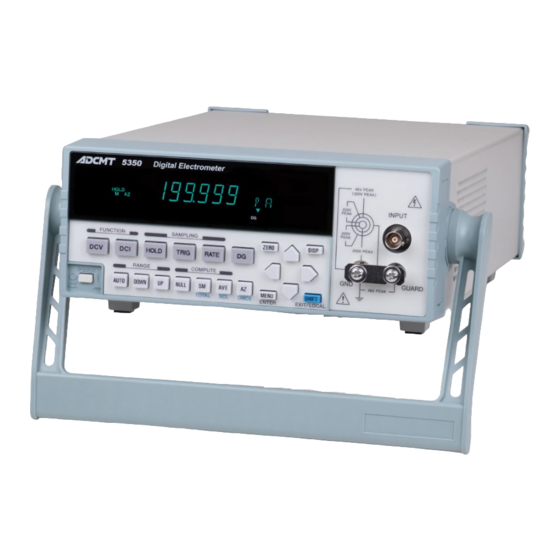
- Page 17 5350 Digital Electrometer Operation Manual 1. PREFACE PREFACE Product Overview The 5350 is a 5 -digit Digital Electrometer that features a DC voltage measurement function and a DC cur- rent measurement function. ranging from 1 V to 19.9999 V •...
-
Page 18: Supplied Accessory List
5350 Digital Electrometer Operation Manual 1.2 Supplied Accessories Supplied Accessories You must fully examine the supplied accessories listed below when you receive the 5350. If any accessories are missing or damaged, contact an ADC CORPORATION sales representative. Specify the part number when ordering. - Page 19 5350 Digital Electrometer Operation Manual 1.3 Input Cables Input Cables The supplied input cable is a double coaxial cable. 100 cm Black Blue Rated voltage: 300 Vrms AC Rated current: 2 A 1. Connector (TXA104-P) 3. Alligator clip (middle) 2. Triaxial cable...
-
Page 20: Optional Accessory List
5350 Digital Electrometer Operation Manual 1.4 Optional Accessories Optional Accessories The 5350 optional accessories are listed below. Specify the part number when ordering. Table 1-2 Optional Accessory List Name Part number Remarks Input cable (TRIAX-TRIAX) A01009 Input cable (TRIAX-BNC) A01011... - Page 21 Obstructing the vents will cause the internal temperature to rise, possibly causing breakdown. * When installing the 5350 into a rack, ensure that exhaust air from other devices is not directed at the vents on the side of the 5350. To prevent the temperature in the rack from rising, install a heat sink fan.
- Page 22 3.1.4, "Power ON and Self Test" to verify that the 5350 properly works both mechanically and electri- cally. If any accessories are missing, the 5350 is mechanically damaged, or any errors of the self test occur, contact an ADC CORPORATION sales representative.
- Page 23 Storage Store the 5350 in a location where the temperature is within the range of -20 C to +70 C. If storing for an extended period, or 90 days or longer, place the 5350 in a moisture-proof bag together with a desiccant to keep it dry, and store it in an area out of direct sunlight.
-
Page 24: Life Limited Parts
1.8 Life Limited Parts Life Limited Parts In addition to the parts listed in "Safety Summary," the 5350 also includes the following parts that are life limited. Contact an ADC CORPORATION sales representative for replacement. Table 1-3 Life Limited Parts... -
Page 25: Substances And Components To Be Sorted
1.9 Product Disposal and Recycling Product Disposal and Recycling Correctly dispose of the 5350 in accordance with local and national regulations. Before disposal, remove the following parts from the product to prevent dispersal of substances that may adversely affect the environment, human health, or the ecosystem. -
Page 27: Screen Annotations
5350 Digital Electrometer Operation Manual 2. FRONT PANEL AND REAR PANEL FRONT PANEL AND REAR PANEL Front Panel 2.1.1 Display The screen adopts a 7-segment and 16-segment vacuum fluorescent display. It displays measured values and setting status. The following figure shows the annotations on the screen. - Page 28 5350 Digital Electrometer Operation Manual 2.1.1 Display Indicator Reference Error 5.12.5 Error Log Memory store 5.11.1 Measurement Memory Store Measurement Auto Range 5.3 Measurement Range NULL operation 5.8.1 NULL Operation Scaling operation 5.8.5 Scaling Operation Buzzer 5.12.1 Buzzer Driving guard 5.5 Driving Guard...
-
Page 29: Keys On Control Panel
5350 Digital Electrometer Operation Manual 2.1.2 Control Panel 2.1.2 Control Panel This section describes the keys on the control panel. For more information on the functional descriptions of the keys, refer to Chapter 3, "BASIC MEASURE- MENTS," Chapter 4, " MENU," and " Chapter 5, "FUNCTIONAL REFERENCE."... - Page 30 5350 Digital Electrometer Operation Manual 2.1.2 Control Panel Key description Reference AUTO: 5.3 Measurement Range Switches the measurement auto range between ON and OFF. The AUTO indicator on the display lights up when the measurement auto range is ON. DOWN: 5.3 Measurement Range...
- Page 31 "TOT," "SCL," and "ONCE" can be set. When the menu screen is displayed, it functions as EXIT key to exit from the menu. When the 5350 is remotely control by GPIB, USB or LAN, it is used as LOCAL key to switch to local control status.
-
Page 32: Input Terminal Section
5350 Digital Electrometer Operation Manual 2.1.3 Input Terminal Section 2.1.3 Input Terminal Section This section describes the input terminal section on the front panel. Figure 2-3 Input Terminal Section Description Reference INPUT terminal: An input connector for DC voltage measurement and DC current measurement. -
Page 33: Rear Panel
Description (Terminal) Reference AC power connector: 3.1 Power Supply Connects the 5350 to AC power supply by using the supplied power cable. Voltage selector fuse holder: 3.1.2 Changing Power Voltage, and Selects voltage to match the AC power supply. Checking and Replacing Power Fuse A fuse is contained inside. -
Page 34: Displayed Messages
5350 Digital Electrometer Operation Manual 2.3 Displayed Messages Displayed Messages The following table shows a list of messages displayed during operation or measurement. If any error messages appear, refer to A.1, "When Problems Occur (Before Requesting Repairs)" or A.2, "Error Message List."... -
Page 35: Power Specification
Table 3-1 below shows the 5350 power specifications. CAUTION: To prevent damage to the 5350, do not apply a voltage or frequency that exceeds the specified range. Ensure that the power voltage setting on the rear panel matches the voltage of the commercial power supply. - Page 36 3.1.2 Changing Power Voltage, and Checking and Replacing Power Fuse 3.1.2 Changing Power Voltage, and Checking and Replacing Power Fuse The 5350 power voltage can be changed manually. This section describes the procedure for changing the power voltage, and checking and replacing the power fuse.
- Page 37 5350 Digital Electrometer Operation Manual 3.1.2 Changing Power Voltage, and Checking and Replacing Power Fuse Rotate the voltage selector until the correct voltage appears in the window. 100 VAC, 120 VAC, 220 VAC or 240 VAC Rated voltage Insert a rated fuse (Refer to Table 3-1).
-
Page 38: Connecting Power Cable
3.1.3 Connecting Power Cable The 5350 is provided with a 3-pin power cable including a ground pin. Always use this power cable to ground the 5350 to a 3-pin power outlet for prevention of electrical shock. Check for any damage to the power cable. - Page 39 Then, connect the power cable. CAUTION: To prevent damage to the 5350, do not apply a voltage or frequency that exceeds the specified range. After the power ON, do not connect a sample or device until the self test is complete to prevent it from being broken.
- Page 40 3.1.6 Warm Up After allowing the 5350 to reach room temperature, turn on the power and warm it up for 60 minutes or longer to secure precise measurements. The accuracies written in Chapter 9, "SPECIFICATIONS" are all specified as values after warming up.
- Page 41 5350 Digital Electrometer Operation Manual 3.2 DC Voltage Measurement DC Voltage Measurement This section describes panel key operation examples and how to connect the input cable for DC voltage mea- surement (DCV). The settings other than described in the operation examples are default settings.
- Page 42 5350 Digital Electrometer Operation Manual 3.2.1 Connection for DC Voltage Measurement 3.2.1 Connection for DC Voltage Measurement The connection varies depending on the whether the signal line is grounded, is not grounded or has voltage to ground. When the driving guard can be set to either ON or OFF, it is recommended to set it to ON.
- Page 43 5350 Digital Electrometer Operation Manual 3.2.1 Connection for DC Voltage Measurement • When the signal line is not grounded • Driving guard OFF Red: Input circuit HI Black: Input circuit LO Blue: GND GND-GUARD terminal: short-circuit Black Blue • Driving guard ON...
- Page 44 5350 Digital Electrometer Operation Manual 3.2.1 Connection for DC Voltage Measurement • When the signal line has voltage to ground • Driving guard OFF Red: Input circuit HI Black: Input circuit LO Blue: GND (not connected) GND-GUARD terminal: short-circuit Black Blue •...
-
Page 45: Maximum Allowable Input Voltage For Dc Voltage Measurement
Precautions for DC Voltage Measurement Do NOT connect the black terminal of the input cable when the driving guard is set to ON. Do NOT exceed the maximum allowable input voltage shown in Table 3-2 to prevent the 5350 from being broken. - Page 46 5350 Digital Electrometer Operation Manual 3.3 DC Current Measurement DC Current Measurement This section describes panel key operation examples and how to connect the input cable for DC current mea- surement (DCI). The settings other than described in the operation examples are default settings.
- Page 47 5350 Digital Electrometer Operation Manual 3.3.1 Connection for DC Current Measurement 3.3.1 Connection for DC Current Measurement The connection varies depending on the whether the signal line is grounded, is not grounded or has voltage to ground. When the driving guard can be set to either ON or OFF, it is recommended to set it to ON.
- Page 48 5350 Digital Electrometer Operation Manual 3.3.1 Connection for DC Current Measurement • When the signal line is not grounded • Driving guard OFF Red: Input circuit HI Black: Input circuit LO Blue: GND GND-GUARD terminal: short-circuit Black Blue • Driving guard ON...
- Page 49 5350 Digital Electrometer Operation Manual 3.3.1 Connection for DC Current Measurement • When the signal line has voltage to ground • Driving guard OFF Red: Input circuit HI Black: Input circuit LO Blue: GND (not connected) GND-GUARD terminal: short-circuit Black Blue •...
-
Page 50: Maximum Allowable Input Voltage For Dc Current Measurement
Do NOT apply voltage between the black terminal and the blue terminal of the input cable when the driving guard is set to ON. Do NOT exceed the maximum allowable input voltage shown in Table 3-3 to prevent the 5350 from being broken. -
Page 51: Voltage Between Input Terminals At Overload
10 V is suddenly connected in an input open status in the 20 mA range, the current limit circuit in the 5350 will be activated by rush current, and the voltage between terminals will become source voltage of when the terminals of input current are opened-circuited. Thus, raise the open-circuit voltage after firmly connecting the input cable. - Page 52 5350 Digital Electrometer Operation Manual 3.3.2 Precautions for DC Current Measurement 10. When the signal source resistance is smaller than the feedback resistance in each range, an error will be added separately from the measurement accuracy. Error examples are shown in the following table.
- Page 53 5350 Digital Electrometer Operation Manual 4. MENU MENU Menu Structure The menu having a hierarchical structure is used to set or execute the functions of the 5350. The menu of the 5350 is a 3-level hierarchical structure as follows: Level 1 Category level Select categories.
-
Page 54: 4.1 Menu Structure
5350 Digital Electrometer Operation Manual 4.1 Menu Structure *1 To be displayed only for DCI *4 To be displayed only for USB *2 To be displayed only when the NULL operation is ON *5 To be displayed only for LAN (OPT5350+06) -
Page 55: Menu Operation Overview
5350 Digital Electrometer Operation Manual 4.2 Menu Operation Overview Menu Operation Overview The following figure shows how to move among the category level, select level and Set/Run level and how to change the parameters. Figure 4-1 Menu Operation Overview... - Page 56 5350 Digital Electrometer Operation Manual 4.2.1 Parameters to Be Selected 4.2.1 Parameters to Be Selected This section describes how to choose parameters from plural items. Example: Setting the memory store to ON The underlines indicate flashing display (cursor). Operation Display...
- Page 57 5350 Digital Electrometer Operation Manual 4.2.2 Parameters to Be Numerically Input 4.2.2 Parameters to Be Numerically Input This section describes how to set parameters by numerical input. Example: Setting the sampling interval to 3 seconds The underlines indicate flashing display (cursor).
- Page 58 5350 Digital Electrometer Operation Manual 4.2.2 Parameters to Be Numerically Input Operation Display...
- Page 59 5350 Digital Electrometer Operation Manual 4.2.3 Parameters to Be Executed 4.2.3 Parameters to Be Executed This section describes how to execute parameters by using the menu. Example: Saving parameters to USER3 The underlines indicate flashing display (cursor). Operation Display Three times...
-
Page 61: Sampling Operation Overview
5350 Digital Electrometer Operation Manual 5. FUNCTIONAL REFERENCE FUNCTIONAL REFERENCE Sampling Operation The following figure shows the sampling operation overview of the 5350. Sampling: FREE RUN Internal trigger Measurement Measurement Measurement Measurement Measurement COMPLETE OUT Sampling interval Sampling interval Sampling interval... - Page 62 5350 Digital Electrometer Operation Manual 5.1.1 Sampling FREE RUN/HOLD 5.1.1 Sampling FREE RUN/HOLD The sampling operation has two functions: FREE RUN and HOLD. • FREE RUN: Generates internal triggers at a specified interval to perform continuous measure- ments. • HOLD: Enters a trigger by the [TRIG] key, "*TRG"...
- Page 63 5350 Digital Electrometer Operation Manual 5.1.3 Trigger Delay The sampling rate is set by using the panel key or the remote command. Sampling rate Panel key Command Indicator Default 500 s IT-1 Dark "F" 2 ms Dark "F" 1 PLC Light "F"...
- Page 64 5350 Digital Electrometer Operation Manual 5.1.4 Sampling Count 5.1.4 Sampling Count The sampling count is a function to set the number of measurements to be executed by one trigger input. The measurements are executed at an interval preset by the sampling interval.
-
Page 65: Relationship Between Sampling Interval And Measurement Time
5350 Digital Electrometer Operation Manual 5.1.5 Sampling Interval When the measurement time is shorter than the sampling interval Internal trigger Measurement Measurement Measurement Measurement Measurement COMPLETE OUT Sampling interval Sampling interval Sampling interval The measurement finishes within the set sampling interval. - Page 66 5350 Digital Electrometer Operation Manual 5.2 Integration Time Integration Time The integration time is time during which the A/D converter of a measuring instrument measures the input signal. The integration time can be set to any values other than predefined by choosing the sampling rate. The unit of the integration time is selectable from second (ms) and PLC.
-
Page 67: Measurement Function And Measurement Range
5350 Digital Electrometer Operation Manual 5.3 Measurement Range Measurement Range The following table shows the measurement range structure of each measurement function. There are two types of measurement range: fixed range to choose ranges manually and auto range to switch to optimal ranges automatically. - Page 68 5350 Digital Electrometer Operation Manual 5.3.1 Measurement Auto Range 5.3.1 Measurement Auto Range The measurement auto range is a function to switch to optimal ranges automatically according measured values. When the auto range is ON, it takes time to obtain an optimal range because the measurement is performed repeatedly until the optimal range is determined.
- Page 69 5350 Digital Electrometer Operation Manual 5.3.3 Measurement Auto Range Level 5.3.3 Measurement Auto Range Level The auto range level is a function to set the count value to 1/1, 1/10 or 1/100 as a reference for raising or lowering the measurement range in the auto range so as to shorten the response time.
- Page 70 5350 Digital Electrometer Operation Manual 5.4 Auto Zero Auto Zero The auto zero corrects automatically the deviation of measured values due to offset drift of the A/D converter by measuring the zero position. The auto zero has three types of settings: OFF, ON and ONCE. Execute the auto zero as necessary if the measuring environment changes or after long-time measurement is performed.
-
Page 71: Driving Guard And Input Cable
5350 Digital Electrometer Operation Manual 5.5 Driving Guard Driving Guard The driving guard is a function to shorten the measurement response in voltage measurement of DUTs in which the impedance of the input signal source is large. When the driving guard is set to ON, the response will be shortened ten times or more compared to at a time when it is set to OFF. -
Page 72: Driving Guard Principles
5350 Digital Electrometer Operation Manual 5.5 Driving Guard Driving guard OFF Rin : Signal line impedance : Capacitance between HI and inner shield : Input signal waveform : Waveform at input cable output end : Buffer amplifier output waveform *Delayed response... - Page 73 For the accuracy of the zero position, refer to the Section 9, "SPECIFICATIONS." When the zero check is set to ON, the input resistance of the 5350 will become 2.2 M approximately and the measurement will stop until the zero check turns OFF.
- Page 74 5350 Digital Electrometer Operation Manual 5.7 Measurement Data Display Measurement Data Display 5.7.1 Measurement Data Display OFF The measurement data display OFF is a function to stop the panel display of measurement data. As the time for updating the measurement data display can be reduced, it is effective in high-speed measurement.
-
Page 75: Math Operation Diagram
5350 Digital Electrometer Operation Manual 5.8 Math Operations Math Operations The math operations of the 5350 can be used in combinations. However, only one operation out of opera- tions listed vertically in Figure 5-4 can be chosen. Scaling Measurement Smoothing... -
Page 76: Smoothing Operation
5350 Digital Electrometer Operation Manual 5.8.2 Smoothing Operation • The NULL operation is released by: • Turning OFF the NULL operation by the panel key or remote command • Changing the measurement function • Initialization (*RST) by using the menu or remote command •... - Page 77 5350 Digital Electrometer Operation Manual 5.8.2 Smoothing Operation The smoothing operation is set by using the panel key or remote command. Smoothing operation Panel key Command Indicator Default "SMO" display (unit display section) *1: The indicator keeps flashing until the number of measurements reaches the number of smoothing.
-
Page 78: Averaging Operation
5350 Digital Electrometer Operation Manual 5.8.3 Averaging Operation 5.8.3 Averaging Operation The averaging operation is a function to calculate the average of the specified times. Example of five times of averaging Measured data Averaging (data 6+..+data 10)/ 5 output (data 1+..+data 5)/ 5 output Figure 5-6 Averaging Operation The averaging operation is set by using the panel key or remote command. -
Page 79: Totalizing Operation
5350 Digital Electrometer Operation Manual 5.8.4 Totalizing Operation • When measured data results in overload (OL) or other errors, the measured data will be excluded from the averaging operation. • Until the specified number of averaging is reached, measured values are not displayed. - Page 80 5350 Digital Electrometer Operation Manual 5.8.4 Totalizing Operation The totalizing operation is set by using the panel key or remote command. Totalizing operation Panel key Command Indicator Default SUM0 SHIFT SUM1 "TOT" display TOTAL (unit display section) The number of totalizing is set by using the menu or remote command.
- Page 81 5350 Digital Electrometer Operation Manual 5.8.5 Scaling Operation 5.8.5 Scaling Operation The scaling operation is a function to perform two types of calculations, NORM and INV against measured data. • NORM S = mX + b S: Scaling operation value X: Measured data •...
- Page 82 " indicator lights up to show the power is ON even when the display is OFF. The "RMT" indicator showing remote control does not light up. If the 5350 is remotely control, press the LOCAL key to switch to the local control status.
- Page 83 The setting parameters (setting contents) can be saved into four areas from User0 to User3 of the non-vol- atile memory. The saved setting parameters can be loaded optionally. In addition, the 5350 can start up with the setting parameters saved in User0.
- Page 84 5350 Digital Electrometer Operation Manual 5.10.3 Setting Parameter Loading 5.10.3 Setting Parameter Loading The setting parameters (setting contents) saved in four areas from User0 to User3 of the non-volatile mem- ory can be loaded optionally. The setting parameters can be loaded by using the menu or remote command.
-
Page 85: Setting Parameters Default Values
5350 Digital Electrometer Operation Manual 5.10.4 Setting Parameter Initialization Table 5-3 Setting Parameters Default Values (1 of 2) MENU INIT Parameter load Default in Type Parameter Factory default *RST, Z Power ON *CLS DFLT DFLT compatible mode Measurement function Sampling... - Page 86 5350 Digital Electrometer Operation Manual 5.10.4 Setting Parameter Initialization Table 5-3 Setting Parameters Default Values (2 of 2) MENU INIT Parameter load Default in Type Parameter Factory default *RST, Z Power ON *CLS DFLT DFLT compatible mode Measurement range DCV...
- Page 87 "Setting Parameter Loading." Initialization to factory default All the setting parameters can be initialized to factory default by operation at power ON. Turn on the 5350 while pressing the key and the key at the same time. "F INI" is displayed at the unit display section and all the parameters returns to factory default.
- Page 88 5350 Digital Electrometer Operation Manual 5.11 Measurement Data Memory 5.11 Measurement Data Memory The measurement data memory is a function to save maximum 100,000 measurement data. The saved mea- surement data can be displayed by key operation and also can be read out by using the remote command.
- Page 89 5350 Digital Electrometer Operation Manual 5.11.2 Measurement Data Memory Recall 5.11.2 Measurement Data Memory Recall The measurement data memory can be recalled by using the menu or remote command. The procedure of recalling the measurement data memory by key operation is described below.
- Page 90 5350 Digital Electrometer Operation Manual 5.11.2 Measurement Data Memory Recall The procedure of recalling the measurement data memory by using the remote command is described below. The following is an example of when 500 measurement data are recalled from the memory address 0 to 499 with the 1,000 measurement data stored in the measurement data memory.
-
Page 91: List Of Events To Activate Buzzer
5350 Digital Electrometer Operation Manual 5.12 System Functions 5.12 System Functions 5.12.1 Buzzer A buzzer notifies when an error occurs or a particular event occurs. The buzzer ON/OFF is set by using the menu or remote command. Buzzer Menu Command... - Page 92 5.12.3 Key Test The 5350 performs the key test to check the operations of panel key switches. The key test is executed from the menu. Pressing any key during key test will make the buzzer sound and display the pressed key on the unit display section. To release the key test, press the "EXIT" key.
- Page 93 Error Log The 5350 saves the error contents in the error log when it detects an error. When there are errors in the error log, the "ERR" indicator lights up. For more information on the errors, refer to Appendix. 2, "Error Message List."...
- Page 94 5350 Digital Electrometer Operation Manual 5.12.6 Information Display 5.12.6 Information Display The information display is a function to check the serial number and the software revision of the 5350 from the menu. Operation Display Remarks Seven times Once Five times...
- Page 95 5.12.7 Panel Lock The panel lock is a function to disable all the panel key operations on the 5350. The panel lock setting requires a four-digit password between 0000 and 9999. The default password is "0000." For how to set the password, refer to Section 5.12.8, "Password Setting."...
- Page 96 5350 Digital Electrometer Operation Manual 5.12.7 Panel Lock The panel lock is set from the menu. The procedure is described below. Operation Display Remarks Seven times Once Seven times Panel lock OFF Once Switch to panel lock ON Waiting for password...
- Page 97 5350 Digital Electrometer Operation Manual 5.12.8 Password Setting 5.12.8 Password Setting A 4-digit password from 0000 to 9999 is required to set the panel lock. The default password is "0000." For how to set the panel lock, refer to Section 5.12.7, "Panel Lock."...
- Page 98 5350 Digital Electrometer Operation Manual 5.12.8 Password Setting Operation Display Remarks Password input Password changed Exit the menu. *3: If the old password is not entered correctly, the password will be changed and the select level will be returned without exiting the menu.
-
Page 99: Interface Setting Items And Factory Default
5350 Digital Electrometer Operation Manual 6. REMOTE CONTROL REMOTE CONTROL Interface Overview The 5350 is equipped with the following four types of interfaces. GPIB interface USB interface LAN interface (factory option) External control signals 6.1.1 Interface Selection The interface is set from the menu on the front panel. - Page 100 5350 Digital Electrometer Operation Manual 6.1.1 Interface Selection An example of how to choose an interface is described below. Example: Setting the interface to USB The underlines indicate flashing display. Operation Display Six times Once Once Once *1: The displayed item may be different depending on the previous menu operation.
- Page 101 • The command timings including operating time in the 8240-compatible mode may be different from those of the 8240. • To maximize the functions of the 5350, set the 8240-compatible mode to OFF except when absolutely necessary. • The 5350 does not have the EXT SRQ input signal of the 8240.
- Page 102 5350 Digital Electrometer Operation Manual 6.1.2 Compatibility with Former Model An example of how to set the compatible mode. Example: Setting the 8240-compatible mode to ON The underlines indicate flashing display. Operation Display Seven times Once Six times Once Once *1: The displayed item may be different depending on the previous menu operation.
- Page 103 GPIB (General Purpose Interface Bus) allows external control of measurement function setting, parameter setting and measurement data reading. • As the GPIB signals are electrically isolated from the measurement signal system of the 5350, the connection of external devices does not affect measured values •...
-
Page 104: Standard Bus Cable
5350 Digital Electrometer Operation Manual 6.2.2 Precautions when Using GPIB 6.2.2 Precautions when Using GPIB Do not use longer connection cables or bus cables than necessary. Operations using 20 m or longer cables are not guaranteed. ADC CORPORATION offers the following standard bus cables. - Page 105 5350 Digital Electrometer Operation Manual 6.2.3 GPIB Setting An example of how to set the GPIB address is described below. In this case, the interface has been already set to GPIB. For how to set the interface to GPIB, refer to Section 6.1.1, "Interface Selection."...
- Page 106 * Download the ADC instruments USB driver from ADC's website. 6.3.2 Connecting with Personal Computer • Connect the USB connector (type B) on the rear of the 5350 to that on a personal computer with a USB cable. • Fully insert all the connectors.
- Page 107 5350 Digital Electrometer Operation Manual 6.3.3 USB Setting An example of how to set the USB ID is described below. In this case, the interface has been already set to USB. For how to set the interface to USB, refer to Section 6.1.1, "Interface Selection."...
-
Page 108: Lan Setting Items
6.4.1 LAN Overview The 5350 can be remotely controlled via the LAN interface by connecting the LAN port on the rear panel to a personal computer. Plug into a network or directly connect to a host computer to operate the 5350. - Page 109 If an invalid address is specified for the network, both the network and the 5350 may operate unexpectedly. NOTE: When the computer and the 5350 exist on different networks (not on the same subnet), it is necessary to set the gateway correctly.
- Page 110 The 5350 uses TCP/IP to communicate with a computer. The TCP/IP connection is performed according to the following procedure: After turning ON, the 5350 waits for the computer sending a TCP/IP connection request with the specified port number (refer to Table 6-5) The computer sends the TCP/IP connection request to the 5350.
-
Page 111: Status Register Overview
6.5 Status Register Status Register The 5350 sends various statuses to the controller in a hierarchical status register structure. This section explains an operational model of the status structure and the allocation of events. * The status register structure conforms to the IEEE standard 488.2-1987. - Page 112 The summary is written into the status byte register. • Data can be written into the enable register. 6.5.1 Event Register The 5350 has the following four types of status registers. • Status Byte Register (STB) • Standard Event Status Register (SESR) •...
-
Page 113: Status Register Structure
5350 Digital Electrometer Operation Manual 6.5.1 Event Register Figure 6-2 shows the status register structure of the 5350. Device Event Status Register Device Event Status Enable Register Reading command: DSE? Reading command: DSR? Setting command: DSEnnn Memory full Smoothing count end... -
Page 114: Status Byte Register Structure
5350 Digital Electrometer Operation Manual 6.5.1 Event Register Status Byte Register (STB) The Status Byte Register summarizes the information from the other status registers. This summary is transmitted as a service request to the controller. The following figure shows the structure of the Status Byte Register. -
Page 115: Status Byte Register (Stb)
5350 Digital Electrometer Operation Manual 6.5.1 Event Register Table 6-6 describes the allocation of the Status Byte Register. This register is read out by using a serial poll or the "*STB?" command. Standard Event Status Register (SESR) Table 6-7 describes the allocation of the Standard Event Status Register. -
Page 116: Standard Event Status Register (Sesr)
5350 Digital Electrometer Operation Manual 6.5.1 Event Register The Status Byte Register is initialized or not initialized under the following conditions: • Initialized when the power is turned ON. • Only RQS (bit 6) is initialized by a serial poll. -
Page 117: Device Event Status Register (Desr)
5350 Digital Electrometer Operation Manual 6.5.1 Event Register The Standard Event Status Enable Register is initialized under the following conditions: • Initialized when the power is turned ON. • Initialized by the "*ESE0" command. • Initialized when the "*PSC" command is set to other than 0. -
Page 118: Error Register (Err)
5350 Digital Electrometer Operation Manual 6.5.1 Event Register Table 6-9 Error Register (ERR) SESR (*1) Bit Description Name Not in use Always 0 "Command execution error" Set to 1 when a command cannot be executed in the present setting. "Command parameter out of range"... - Page 119 Enable Register The bits of an enable register are expressed in decimal. The Error Register does not have the corresponding enable register. The 5350 has the following three types of enable registers: Service Request Enable Register Standard Event Status Enable Register...
-
Page 120: Status Register Structure In 8240-Compatible Mode
5350 Digital Electrometer Operation Manual 6.5.3 Status Registers in 8240-Compatible Mode 6.5.3 Status Registers in 8240-Compatible Mode Table 6-4 shows the status register structure in the 8240-compatiblel mode. Table 6-10 describes the allo- cation of the Status Byte Register, Table 6-11 describes that of the Standard Event Status Register, and Table 6-12 describes that of the Error Register. -
Page 121: Status Byte Register In 8240-Compatible Mode
5350 Digital Electrometer Operation Manual 6.5.3 Status Registers in 8240-Compatible Mode Table 6-10 Status Byte Register in 8240-Compatible Mode Name Description Set to 1 when measurement ends. Measure End Set to 0 when measurement starts or the measurement data output is OFF: complete. -
Page 122: Standard Event Status Register In 8240-Compatible Mode
Initialized when the "*PSC" command is set to other than 0. NOTE: The 5350 does not have the EXT SRQ input signal. The EXT SRQ input that is assigned to bit 6 of the Standard Event Status Register of the 8240 is not used on the 5350. -
Page 123: Error Register In 8240-Compatible Mode
5350 Digital Electrometer Operation Manual 6.5.3 Status Registers in 8240-Compatible Mode Table 6-12 Error Register in 8240-Compatible Mode SESR (*1) Bit Description Name Not in use Always 0 Not in use Always 0 Not in use Always 0 "No recall data"... -
Page 124: Main Header
5350 Digital Electrometer Operation Manual 6.6 Measurement Data Format (Talker Format) Measurement Data Format (Talker Format) This section describes the output format when reading the measurement data or measurement data memory. 6.6.1 Measurement Data Header Header ON: The main header and sub header of three characters and a space are inserted. -
Page 125: Mantissa Part And Exponent Part
5350 Digital Electrometer Operation Manual 6.6.1 Measurement Data Mantissa part and exponent part Table 6-15 Mantissa Part and Exponent Part Normal mode 8240-compatible mode Function Range Mantissa part Exponent part Mantissa part Exponent part ddd.ddd ddd.dd DC voltage measurement 200 mV... -
Page 126: Mantissa Part And Exponent Part At Error Occurrence
5350 Digital Electrometer Operation Manual 6.6.1 Measurement Data Table 6-16 Mantissa Part and Exponent Part at Error Occurrence 8240-compatible Function Range Normal mode mode 999.999E+99 Overload DC voltage 200 mV +999.99E+99 (OL) measurement 9999.99E+99 +9999.9E+99 99.9999E+99 20 V +99.999E+99 999.999E+99... - Page 127 5350 Digital Electrometer Operation Manual 6.6.2 Memory Recall Data 6.6.2 Memory Recall Data The stored memory data can be recalled collectively from a specified range. It is possible to read out a continuous range within 100,000 data from No.0 to No. 99,999.
- Page 128 5350 Digital Electrometer Operation Manual 6.7 Remote Commands Remote Commands The 5350 can operate in accordance with received remote commands without direct panel operation. The remote commands available for the 5350 are described in the following sections: Section 6.7.3, "Remote Command Index"...
- Page 129 A remote command that ends with a question mark "?" is called "query command." Query commands are used to ask the status of the 5350. When receiving these commands, the 5350 output character strings according to the setting status. For more information on the response of each query command, refer to Section 6.7.4, "Remote Com- mand List."...
- Page 130 5350 Digital Electrometer Operation Manual 6.7.2 Data Format 6.7.2 Data Format The 5350 uses the following data formats for data input and output. Any format is acceptable to input data to the 5350. NR1 format: Integer type Example: +100, -100...
- Page 131 5350 Digital Electrometer Operation Manual 6.7.3 Remote Command Index 6.7.3 Remote Command Index Remote command Page Remote command Page *CLS ............6-41 DP? ............6-42 *ESE ............6-41 DS ............6-43 *ESE? ............6-41 DS? ............6-43 *ESR? ............. 6-41 DSE ............
- Page 132 5350 Digital Electrometer Operation Manual 6.7.3 Remote Command Index OM ............6-37 OM? ............6-37 OMX? ............. 6-37 R .............. 6-35 R? ............6-35 RE ............6-37 RE? ............6-37 RINI ............6-42 RLH ............6-38 RLH? ............6-38 RNG? ............6-35 RX? ............
- Page 133 5350 Digital Electrometer Operation Manual 6.7.4 Remote Command List 6.7.4 Remote Command List The "Default" column shows default settings at factory shipment or in the 8240-compatible mode. The items in the "Operation" column show the following: • During calibration: Operation availability during calibration •...
-
Page 134: Remote Command List
5350 Digital Electrometer Operation Manual 6.7.4 Remote Command List Table 6-18 Remote Command List (2 of 10) Default Operation Classification Item Command Description At factory Compatible During Compatible shipment mode calibration mode Measurement Integration time ITP<data> Integration time setting (unit: PLC) - Page 135 5350 Digital Electrometer Operation Manual 6.7.4 Remote Command List Table 6-18 Remote Command List (3 of 10) Default Operation Classification Item Command Description At factory Compatible During Compatible shipment mode calibration mode Measurement Driving guard Driving guard OFF Driving guar ON...
- Page 136 5350 Digital Electrometer Operation Manual 6.7.4 Remote Command List Table 6-18 Remote Command List (4 of 10) Default Operation Classification Item Command Description At factory Compatible During Compatible shipment mode calibration mode Measurement Range limit RLH<num1>, Upper limit and lower limit setting for range switching...
- Page 137 5350 Digital Electrometer Operation Manual 6.7.4 Remote Command List Table 6-18 Remote Command List (5 of 10) Default Operation Classification Item Command Description At factory Compatible During Compatible shipment mode calibration mode Arithmetic Smoothing TI<num> Smoothing operation count setting operation...
- Page 138 5350 Digital Electrometer Operation Manual 6.7.4 Remote Command List Table 6-18 Remote Command List (6 of 10) Default Operation Classification Item Command Description At factory Compatible During Compatible shipment mode calibration mode Data memory Measurement data Measurement data memory store OFF...
- Page 139 5350 Digital Electrometer Operation Manual 6.7.4 Remote Command List Table 6-18 Remote Command List (7 of 10) Default Operation Classification Item Command Description At factory Compatible During Compatible shipment mode calibration mode Remote Status *CLS Initializes the status register. *SRE<num>...
- Page 140 5350 Digital Electrometer Operation Manual 6.7.4 Remote Command List Table 6-18 Remote Command List (8 of 10) Default Operation Classification Item Command Description At factory Compatible During Compatible shipment mode calibration mode Remote D/A output D/A output OFF D/A output ON...
- Page 141 5350 Digital Electrometer Operation Manual 6.7.4 Remote Command List Table 6-18 Remote Command List (9 of 10) Default Operation Classification Item Command Description At factory Compatible During Compatible shipment mode calibration mode System Measured value Measured value display OFF display...
- Page 142 5350 Digital Electrometer Operation Manual 6.7.4 Remote Command List Table 6-18 Remote Command List (10 of 10) Default Operation Classification Item Command Description At factory Compatible During Compatible shipment mode calibration mode Calibration Calibration mode CAL0 Calibration mode OFF Unsetta-...
-
Page 143: Sample Program List
5350 Digital Electrometer Operation Manual 6.7.5 Sample Program 6.7.5 Sample Program This section describes program examples to remotely control the 5350 via GPIB or USB. Download these programs from ADC's website. http://www.adcmt.com/samplesoft/samplesoft_01.html Table 6-19 Sample Program List Program content Example 1 DC voltage measurement: Measures DC voltage in the 200 mV range with sampling HOLD by trigger input. -
Page 144: List Of External Control Signals
6.8.1 TRIGGER IN (External Trigger Input) The TRIGGER IN (external trigger input) is a signal to make the 5350 start measurement externally. It is available only when the SAMPLING on the front panel is set to HOLD. The 5350 starts sampling at the falling edge of the negative pulse of the input signal. -
Page 145: Trigger In Equivalent Circuit
5350 Digital Electrometer Operation Manual 6.8.1 TRIGGER IN (External Trigger Input) Input a TTL signal or contact signal. Figure 6-5 TRIGGER IN Equivalent Circuit TRIGGER IN COMPLETE OUT (Multi output) Measurement Calculation Measurement Calculation Internal operation Figure 6-6 Operation Timing of TRIGGER IN and COMPLETE OUT NOTE: Ensure that the TRIGGER input signal and trigger by key operation key or remote trigger do not overlap. -
Page 146: Complete Out Equivalent Circuit
5350 Digital Electrometer Operation Manual 6.8.2 COMPLETE OUT (Measurement End Output) 6.8.2 COMPLETE OUT (Measurement End Output) The COMPLETE OUT (measurement end output) is a signal to notice the measurement end to the outside. The pulse width and the output timing settings can be changed. -
Page 147: Operation Timing Of Complete Out (Single Output)
5350 Digital Electrometer Operation Manual 6.8.2 COMPLETE OUT (Measurement End Output) TRIGGER IN COMPLETE OUT (Single output) Measurement Calculation Measurement Calculation Measurement Calculation Internal operation Sampling Count Figure 6-8 Operation Timing of COMPLETE OUT (Single Output) 6-49... - Page 148 5350 Digital Electrometer Operation Manual 6.8.3 Selecting Pulse Width of Measurement End Output 6.8.3 Selecting Pulse Width of Measurement End Output The pulse width of the COMPLETE OUT (measurement end output) can be switched between 100 s and 1 ms. The default setting is 100 s. In the 8240-compatible mode, it is set to 1 ms.
- Page 149 5350 Digital Electrometer Operation Manual 6.8.4 Selecting Output Mode of Measurement End Output 6.8.4 Selecting Output Mode of Measurement End Output The COMPLETE OUT (measurement end output) can be switched between single output mode and multi output mode. When the sampling count is se to more than one, the measurement end is output for every measurement in the multi output mode.
-
Page 150: Relationship Between Measured Data And D/A Output Voltage
5350 Digital Electrometer Operation Manual 6.8.5 D/A OUT (D/A Output) 6.8.5 D/A OUT (D/A Output) Measured data is converted to analog signals by the D/A converter and is output to the D/A OUT terminal on the rear panel. Any three consecutive digits (CCC) of the measured data are converted to voltage in the range from -1000 mV to +1000 mV. -
Page 151: D/A Output Setting List
5350 Digital Electrometer Operation Manual 6.8.5 D/A OUT (D/A Output) Table 6-24 D/A Output Setting List Display digits and selected digits Output example Setting Description Displayed value: digits digits digits digits digits digits 123456 +123 mV Outputs 10 to 10 digits of a displayed value. - Page 152 5350 Digital Electrometer Operation Manual 6.8.5 D/A OUT (D/A Output) An example of how to set the D/A OUT is described below: Example: Setting the D/A OUT output digits to "1CCC99" The underlines indicate flashing display. Operation Display Six times...
-
Page 153: Output Voltage Of Amp Out Terminal
5350 Digital Electrometer Operation Manual 6.8.6 Preamplifier Output (AMP OUT) 6.8.6 Preamplifier Output (AMP OUT) The preamplifier output is a function to output the preamplifier output voltage of the input circuit to the outside without isolation. For the internal connection, see Figure 6-10, "Internal Connection of AMP OUT Terminal."... -
Page 154: Internal Connection Of Amp Out Terminal
5350 Digital Electrometer Operation Manual 6.8.6 Preamplifier Output (AMP OUT) • DCV function • DCI function Driving guard OFF Driving guard OFF Figure 6-10 Internal Connection of AMP OUT Terminal CAUTION: • The AMP OUT LO terminal is connected to the input circuit LO internally. The input terminal LO is con- nected the INPUT terminal or the input cable in different ways depending on the driving guard setting and the measurement function. - Page 155 5350 Digital Electrometer Operation Manual 7. PERFORMANCE TEST PERFORMANCE TEST This chapter describes the performance test that checks whether the 5350 operates normally in the specified accu- racies. Performance test The performance test checks whether the 5350 operates normally in the specified accuracies. It should be performed from time to time.
- Page 156 G) is within the accuracies described in Chapter 9, "SPECIFICATIONS." Change the range of the 5350 to 2000 pA to 200 A and the standard resistance to 1 G to 100 k and verity the measured values at full scale in the same way by performing Step .
- Page 157 Verify that the difference between the 5350 measured values and the applied current is within the accuracies described in Chapter 9, "SPECIFICATIONS." Change the range of the 5350 to 20 mA, and verity the measured values at full scale in the same way by performing Step .
- Page 159 5350 Digital Electrometer Operation Manual 8. CALIBRATION CALIBRATION In order to use the 5350 in the specified accuracies, periodic calibration once a year is necessary. This chapter describes how to calibrate the 5350 to maintain the specified accuracies described in Chapter 9, "SPECIFICATIONS."...
-
Page 160: Instruments Necessary For Calibration
5350 Digital Electrometer Operation Manual 8.1 Instruments and Cable Necessary for Calibration Instruments and Cable Necessary for Calibration Use the measuring instruments necessary for calibration shown below or measuring instruments that have equal or higher performances as standard. Table 8-1 Instruments Necessary for Calibration... - Page 161 Temperature 23 C 3 C Relative humidity 70 % or lower Allow the 5350 to warm-up for one hour or longer before calibration. After calibration, note the dates of the calibration and the next scheduled calibration for convenience. Execute calibration remotely via USB, GPIB or LAN, or manually by panel key operation.
-
Page 162: Connection For Voltage Measurement Calibration At Zero Position (Red-Blue Shorted)
5350 Digital Electrometer Operation Manual 8.3 Connections Connections The following figures show connections for calibrating voltage measurement, current measurement, and D/ A OUT. These connections are applied to the performance test described in Chapter 7, "PERFORMANCE TEST," too. Blue Figure 8-1 Connection for Voltage Measurement Calibration at Zero Position (Red-Blue Shorted) -
Page 163: Connection For Current Measurement Calibration At Full Scale In 200 Pa To 200 A Range
5350 Digital Electrometer Operation Manual 8.3 Connections DC voltage current source (6166) A01044 + A08531 (Red) A01044 + A08531 (Black) Figure 8-5 Connection for Current Measurement Calibration at Full Scale in 200 pA to 200 A Range DC voltage current source (6166) Blue Figure 8-6 Connection for Current Measurement Calibration at Full Scale in 2000 A to 20 mA Range... -
Page 164: Voltage Measurement Calibration Ranges
5350 Digital Electrometer Operation Manual 8.4 Calibration Points and Tolerance Ranges Calibration Points and Tolerance Ranges For calibration, use measuring instruments satisfying the required accuracies described in Table 8-1, "Instru- ments Necessary for Calibration", meeting the tolerance ranges shown in the following tables. -
Page 165: D/A Out Calibration Ranges
5350 Digital Electrometer Operation Manual 8.4 Calibration Points and Tolerance Ranges Table 8-5 D/A OUT Calibration Ranges Recommended Range Adjustable range Tolerance range calibration point 0.5 mV ZERO 0.000 V -0.1 V to+0.1 V 1 mV FULL +1.000 V +0.9 V to+1.1 V... -
Page 166: Calibration Flow
5350 Digital Electrometer Operation Manual 8.5 Remote Calibration Remote Calibration 8.5.1 Remote Calibration Flowchart Figure 8-8 to Figure 8-11 show the calibration flows by using the remote commands via GPIB, USB or LAN. Fore more information on the remote commands, refer to the calibration parameters in Section 6.7.4, "Remote Command List."... -
Page 167: Voltage Measurement Calibration Flow
5350 Digital Electrometer Operation Manual 8.5.1 Remote Calibration Flowchart Voltage measurement calibration [Range setting] 200 mV range? 2000 mV range? 20 V range [Zero calibration] Zero calibration connection XDT zero data [Full-scale calibration] Full-scale calibration connection XDT full-scale data [Zero check]... -
Page 168: Current Measurement Calibration Flow
5350 Digital Electrometer Operation Manual 8.5.1 Remote Calibration Flowchart Current measurement calibration [Range setting] 200 pA range? 2000 pA range? 2000 A range? 20 mA range [Zero calibration] Zero calibration connection XDT zero data [Full-scale calibration] Full-scale calibration connection XDT full-scale data... -
Page 169: D/A Out Calibration Flow
5350 Digital Electrometer Operation Manual 8.5.2 Remote Calibration Data Saving D/A OUT calibration D/A OUT calibration connection [Zero calibration] [Zero check] XS zero data XS zero data DMM data acquisition Calibration result data DMM data acquisition save/display XDT DMM zero data... - Page 170 5350 Digital Electrometer Operation Manual 8.6 Manual Calibration Manual Calibration Set the calibration mode to "ON" in accordance with the following procedure: Category level Select level Set/Run level MENU 9 CAL CL.MOD ENTER EXIT To set the calibration item successively, press [] instead of [EXIT] to move to "CL.FNC" and go on to Section 8.6.1, "Voltage Measurement Calibration (DCV)."...
- Page 171 5350 Digital Electrometer Operation Manual 8.6.1 Voltage Measurement Calibration (DCV) Connection and calibration point • Connect the external instrument in reference to Section 8.3, "Connections." • For the calibration point and the tolerance range, refer to Table 8-3, "Voltage Measurement Cal- ibration Ranges."...
- Page 172 5350 Digital Electrometer Operation Manual 8.6.2 Current Measurement Calibration (DCI) 8.6.2 Current Measurement Calibration (DCI) Set the calibration item to "current measurement calibration (DCI)" in accordance with the following procedure: Category level Select level Set/Run level DAOUT MENU ENTER EXIT 9 CAL CL.FNC...
- Page 173 5350 Digital Electrometer Operation Manual 8.6.2 Current Measurement Calibration (DCI) Range change • To calibrate all the ranges, change the range from 200 pA to 20 mA with [RANGE UP] and [RANGE DOWN] and repeat Step 3 and Step 4.
- Page 174 5350 Digital Electrometer Operation Manual 8.6.3 D/A OUT Calibration (DAOUT) 8.6.3 D/A OUT Calibration (DAOUT) Set the calibration item to "D/A OUT calibration (DAOUT)" in accordance with the following pro- cedure: Category level Select level Set/Run level ENTER DAOUT MENU 9 CAL CL.FNC...
- Page 175 5350 Digital Electrometer Operation Manual 8.6.4 Manual Calibration Data Saving and Ending Full scale calibration • Set the [CL.DAV] to 1.0000 V and press [EXIT] to exit from the MENU. • Press [HOLD] and input the read value from the multimeter with [], [], [] and [].
- Page 176 5350 Digital Electrometer Operation Manual 8.6.5 Manual Calibration Data Initialization 8.6.5 Manual Calibration Data Initialization Initialize the calibration data in accordance with the following procedure. Category level Select level Set/Run level MENU ENTER 9 CAL CL.INI 8-18...
- Page 177 5350 Digital Electrometer Operation Manual 9. SPECIFICATIONS SPECIFICATIONS Unless otherwise specified, the specifications are guaranteed for one year under the conditions of a tempera- ture of 23 5 C and a relative humidity not exceeding 70 %. DC Voltage Measurement Accuracy (% of reading + digit)
- Page 178 5350 Digital Electrometer Operation Manual 9.2 DC Current Measurement DC Current Measurement Accuracy (% of reading + digit) Temperature coefficient Settling time Measurement Maximum Resolution (ms) (% of reading +digit)/ C Zero check OFF Zero check ON range display *1,*2...
- Page 179 5350 Digital Electrometer Operation Manual 9.2 DC Current Measurement Noise rejection ratio (at 50/60 Hz 0.08 %) • Integration time NMRR Integral multiple of 1 PLC 60 dB or more Other 0 dB Maximum allowable input capacitance: 0.1 F •...
- Page 180 5350 Digital Electrometer Operation Manual 9.3 Measurement Time and Display Digits Measurement Time and Display Digits Measurement speed Integration time (IT) Display digits *3 Power frequency Power frequency 50 Hz 60 Hz 500 μs 1000 readings / s 19999 200 readings / s...
- Page 181 5350 Digital Electrometer Operation Manual 9.4 Math Operations Math Operations • NULL operation: Displayed value (NULL) = Measured value - NULL constant • Smoothing operation: Displayed value (SM) = Moving average of a specified number of times • Averaging operation: Displayed value (AVE) = Average of a specified number of times •...
- Page 182 5350 Digital Electrometer Operation Manual 9.5 Advanced Setting Functions Advanced Setting Functions • Auto zero: Cancels the offset errors of the A/D converter. • Zero check: Cancels the offset the input amplifier. • Measurement range upper limit/lower limit: Specifies the upper limit and the lower limit of the measurement range to reduce the measurement delay due to unnecessary ranging.
-
Page 183: Interface Function
5350 Digital Electrometer Operation Manual 9.6 Interface Function Interface Function • Remote command: Compliant to the ADC command system and the 8240 commands • GPIB: 1. Interface functions: SH1, AH1, T5, L4, SR1, RL1, PP0, DC1, DT1, C0, E2 2. Standard: IEEE488.2... - Page 184 5350 Digital Electrometer Operation Manual 9.6 Interface Function • AMP OUT (preamplifier output) 1. Function: Outputs impedance-converted DC voltage according to the input voltage or current. 2. Connector: Safety 200 mV, 2 V or 20 V at full scale 3. Output voltage: (depending on the measurement function) 5.
- Page 185 5350 Digital Electrometer Operation Manual 9.7 General Specifications General Specifications Temperature 0 C to +50 C • Operating environment: Relative humidity 85 % or less without condensation Temperature -20 C to +70 C • Storage environment: Relative humidity 85 % or less without condensation •...
- Page 186 5350 Digital Electrometer Operation Manual 9.7 General Specifications DCI driving guard ON INPUT HI INPUT LO 200 Vpeak GUARD 20 mApeak 200 Vpeak (*3) 46 Vpeak 46 Vpeak 200 Vpeak *3 The INPUT LO and the GUARD are connected internally.
-
Page 187: Items To Be Inspected Before Requesting Repair
A.1 When Problems Occur (Before Requesting Repairs) If any problem is encountered when using the 5350, inspect the unit referring to Table A-1. If the problem cannot be solved by the suggested remedial actions, contact an ADC CORPORATION sales representative. - Page 188 5350 Digital Electrometer Operation Manual Table A-1 Items to be Inspected before Requesting Repair (2 of 2) Q (Symptom) A (Cause and Solution) 4 The source values or measured values are Cause: Function or range settings have an error. unstable or result in errors.
-
Page 189: Error Message List
5350 Digital Electrometer Operation Manual A.2 Error Message List If an error occurs when using the 5350, an error code appears on the screen. The contents are explained in the following table: Table A-2 Error Message List (1 of 2) - Page 190 5350 Digital Electrometer Operation Manual Table A-2 Error Message List (2 of 2) Error occurrence timing Continua Error No. Classification Error message Description tion after Power Self Problem code error test occurrence Remote com- -102 Cmd Syntax Command syntax error...
- Page 191 5350 Digital Electrometer Operation Manual A.3 Execution Time GPIB/USB remote execution time (typical value) Controller: Windows 10 GPIB controller: National Instruments USB-GPIB USB driver: ADC instruments USB deriver Language: Visual Basic Command execution time (ms) Classification Item Command Content Condition...
- Page 192 5350 Digital Electrometer Operation Manual Data read time (ms) Classification Item Command Content Condition GPIB Measurement Measurement function Measurement function query Default setting Measurement range Measurement range query Default setting Sampling rate Sampling rate query Default setting Zero check Zero check query...
- Page 193 5350 Digital Electrometer Operation Manual Measurement execution time (ms) Time from measurement by trigger input (*TRG) to completion of data output to GPIB, USB or LAN Condition (at highest speed) Measurement function DCV/DCI Measurement range Fixed Sampling HOLD Auto zero...
- Page 195 DIMENSIONAL OUTLINE DRAWING EXT-1...
- Page 197 ALPHABETICAL INDEX ALPHABETICAL INDEX 5350 Digital Electrometer Operation Manual ALPHABETICAL INDEX [ I ] AMP OUT ..........6-55 Information Display ........ 5-34 Auto Zero ..........5-10 Input Cables ..........1-3 Averaging Operation ....... 5-18 Input Terminal Section ......2-6 Integration Time ........5-6 Interface Overview .........
- Page 198 5350 Digital Electrometer Operation Manual Alphabetical Index Power Supply .......... 3-1 Preamplifier Output ........ 6-55 Zero Check ..........5-13 Precautions for DC Current Measurement 3-16 Precautions for DC Voltage Measurement 3-11 Product Disposal and Recycling ..... 1-9 Product Overview ........1-1 Rear Panel ..........
- Page 199 IMPORTANT INFORMATION FOR ADC CORPORATION SOFTWARE PLEASE READ CAREFULLY: This is an important notice for the software defined herein. Computer programs including any additions, modifications and updates thereof, operation manuals, and related materials provided by ADC CORPORATION (hereafter referred to as "SOFTWARE"), included in or used with hardware produced by ADC CORPORATION (hereafter referred to as "PRODUCTS").
- Page 200 5. EXCEPT TO THE EXTENT EXPRESSLY PROVIDED HEREIN, ADC CORPORATION HEREBY EXPRESSLY DISCLAIMS, AND THE PURCHASER HEREBY WAIVES, ALL WARRANTIES, WHETHER EXPRESS OR IMPLIED, STATUTORY OR OTHERWISE, INCLUDING, WITHOUT LIMITATION, (A) ANY WARRANTY OF MERCHANTABILITY OR FITNESS FOR A PARTICULAR PURPOSE AND (B) ANY WARRANTY OR REPRESENTATION AS TO THE VALIDITY, SCOPE, EFFECTIVENESS OR USEFULNESS OF ANY TECHNOLOGY OR ANY INVENTION.
Need help?
Do you have a question about the 5350 and is the answer not in the manual?
Questions and answers