Sign In
Upload
Manuals
Brands
ADCMT Manuals
Measuring Instruments
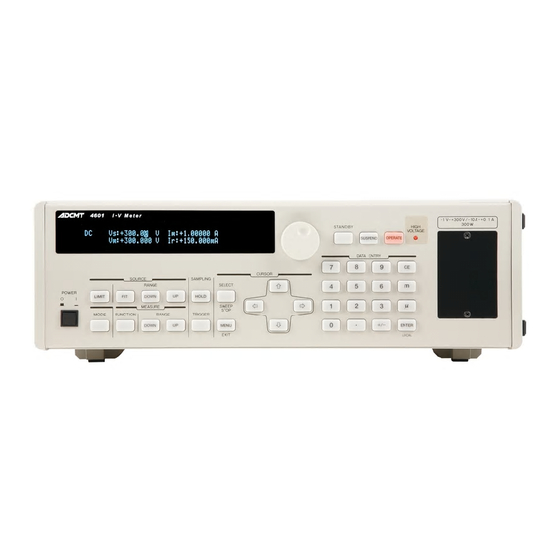
4601 I-V Meter
ADCMT 4601 I-V Meter Manuals
Manuals and User Guides for ADCMT 4601 I-V Meter. We have
1
ADCMT 4601 I-V Meter manual available for free PDF download: Operation Manual
ADCMT 4601 I-V Meter Operation Manual (236 pages)
Brand:
ADCMT
| Category:
Measuring Instruments
| Size: 4 MB
Table of Contents
Table of Contents
9
Preface
19
Product Overview
19
Reference Cell Measurement Terminal
20
Output Range
23
Maximum Power Limitation at Time of Continuous Loading
24
Duty Ratio Limitation at Time of 300 W (Sink)/30 W (Source) Loading
25
Supplied Accessories
26
Output Unit
26
Standard Accessory List
26
Output Unit List
26
Removing Panel
27
Mounting Output Unit
27
Optional Accessories
28
Options
28
Optional Accessory List
28
Operating Environment
29
Environmental Conditions
29
Operating Environment
30
Power Specification
31
Set Power Voltage Indicator
31
Power Supply Specification
31
Changing Power Voltage, and Checking and Replacing Power Fuse
32
1.6.4 Power Cable
33
Connecting Power Cable
34
Operating Check
35
Display at Power on
35
Cleaning, Storage, and Transport Methods
36
Cleaning
36
Storage
36
Display During OPERATE
36
Transport
37
Warm-Up Time
37
1.10 Calibration
37
1.11 Life Limited Parts
38
1.12 Product Disposal and Recycling
39
Panel Descriptions
41
Front Panel
41
Display Section
42
SOURCE LIMIT Section
42
2.1.3 MODE Section
43
MEASURE Section
43
SAMPLING Section
44
CURSOR Section
45
DATA ENTRY Section
46
OPERATE Section
47
Front Output Unit Section
48
Front Output Unit Section (for Safety Socket)
48
POWER Switch
49
Screen Display (Annotations)
49
Rear Panel
51
Basic Operations
53
Settings and Operations from Source to Measurement
53
Power on
54
DC Source Mode
55
Setting and Outputting Voltage Source Value
55
Setting Current Limits
58
3.2.3 Changing Measurement Function and Range
61
Sweep Source Mode
64
Sweep Source and Measurement Method
64
Checking Measured Values
65
Setting Current Limits
66
Changing Reference Cell Current Range
66
Setting Memory Sweep Data
66
3.4 Menu Operation
69
Menu Structure
69
How to Operate Menu
71
Initializing Setting Conditions
73
Initializing Parameters from Menu
73
Restoring to Factory Default Settings
74
Saving and Loading Parameters
75
Loading Parameters
75
Saving Parameters
76
Auto Parameter Loading at Power on
78
Menu Index
81
Panel Key Descriptions
83
CURSOR Key (Cursor Moving)
83
DATA ENTRY Keys (Source Value Setting)
83
DOWN Key (Voltage Source or Current Limit Range Down)
83
DOWN Key (Measurement Range Down)
83
EXIT Key (Menu Setting Cancellation)
84
FIT Key (Optimal Voltage Source or Current Limit Range)
84
FUNCTION Key (ADC3 Measurement Function Selection)
84
HOLD Key (Sampling Selection)
84
LIMIT Key (Current Limit Setting)
84
MENU Key (Parameter Setting)
85
MODE Key (Source Mode Selection)
90
OPERATE Key (Output ON/OFF)
90
SELECT Key (Numeric Item Selection)
90
STANDBY Key (Output OFF)
91
SUSPEND Key (Output OFF)
91
SWEEP STOP Key (Sweep Stop)
91
TRIGGER Key (Measurement Trigger and Sweep Start)
91
UP Key (Voltage Source Range up or Current Limit Range Up)
91
UP Key (Measurement Range Up)
91
Operational Descriptions
93
Connection of Sample
93
Connection with Output Unit
93
Output Unit
93
Reference Cell Measurement Terminal
94
Connection with Output Unit
94
External Voltage Measurement Terminal
95
Temperature Measurement Terminal
95
Thermocouple Connector
95
Platinum Resistance Bulb and IC Sensor Connector
95
DC Source Mode
97
Operations in DC Source Mode
97
Sweep Source Mode
99
Operational Descriptions of Sweep Source Mode
99
Source Measurement Operations in Sweep Source Mode
101
Reverse Function
102
Reverse Operations in Sweep Source Mode
102
Output at Sweep End
103
Source and Measurement Timings
103
Basic Source and Measurement Timings
103
Restrictions on Time Parameters
104
5.2.6 Settling Time
107
Settling Time and Measurement Delay Time
107
Source Measurement Function
110
Source Range
110
Suspend Function
110
Conceptual Diagram of Output Status
110
High Voltage Indicator Lightning Condition
114
Measurement Function and Range
114
5.3.6 Zero Measurement
116
Measurement Data Memory
117
Alarm Detection
118
Current Limit Detection
118
Oscillation Detection
118
Oscillation Detection Sensitivity
118
Relay Life Cycle Detection
119
Relay Counter Structure
119
5.4.4 Other Alarm Detection
121
Rear Input and Output Signal
122
External Control Signals
124
External Control Signal Functions
124
Restrictions on Using External Trigger
125
Restrictions on Tp, Tp (Ext), Th and Th (Ext)
125
TA Value
125
Restriction on Top
126
Operating Multiple 4601
128
Synchronous Operation
128
Connection for Three Unit Synchronous Operation Using SYNC out
128
Setting for Three Unit Synchronous Operation Using SYNC out
128
Parallel Connection
131
Series Connection
132
Series Connection
134
Serial Sweep
135
Serial Sweep Output Example and Connection Method
137
Self Test
138
Self Test Items
138
Error Log
141
Operational Principles
143
Block Diagram
143
Voltage Source/Voltage Measurement/Current Measurement Terminal Circuit
144
ADC3 Measurement Circuit
145
Remote Programming
147
Using Interface
147
Selecting Interface
147
Gpib
148
Overview
148
Interface Function
148
Precautions When Using GPIB
149
Standard Bus Cable
149
Setting GPIB
150
Usb
152
Overview
152
USB Specifications
152
Connecting with PC
152
Precautions When Using USB
152
Setting USB ID
153
Status Register Structure
155
Status Byte Register
156
Measurement Event Register
156
Questionable Event Register
156
Status Register Structure
157
Standard Event Status Register
158
Data Output Format
161
Measured Value Output
161
Output Target Selection
161
Output Format Selection
162
ASCII Output Format
162
Binary Output Format
166
Remote Commands
168
Data Format
169
Remote Command List
170
Sample Program
181
Performance Test
183
Measuring Instruments Necessary for Performance Test
183
Connections
183
Test Method
183
Self-Test, Display, Key, and Buzzer
183
Voltage Source and Voltage Measurement Test
184
Current Measurement Test
184
Current Limit Test
184
7.3.5 Reference Cell Current Measurement Test
185
Pt Temperature Measurement Test
185
AD590 Temperature Measurement Test
185
Type T Thermocouple Temperature Measurement Test
186
External Voltage Measurement Test
186
Calibration
187
Preparation for Calibration
187
Measuring Instruments Necessary for Calibration
187
Precautions
187
Connections
188
Connections for Calibration (1 of 4)
188
Connections for Calibration (2 of 4)
189
Connections for Calibration (3 of 4)
190
Connections for Calibration(4 of 4)
191
Calibration Points and Tolerance Ranges
192
Calibration Tolerance Ranges
192
Calibration Procedure
197
Calibration Procedure
198
Calibration Procedure
199
Calibration Procedure
200
Calibration Procedure
201
Calibration Procedure
202
Calibration Procedure
204
Overall Calibration Procedure
204
Voltage Source Calibration
204
Voltage Measurement Calibration
205
Current Measurement Calibration
205
Current Limit Calibration
206
ADC3 Measurement Calibration
207
Reference Junction Temperature Calibration
208
Specifications
209
9.1 Voltage Source/Voltage Measurement/Current Measurement Terminal OUTPUT/SENSE Terminal
210
9.2 Voltage Measurement Terminal Em Terminal
211
9.3 Reference Cell Measurement Terminal CELL Ir Terminal
212
9.4 Temperature Measurement Thermocouple Measurement Terminal Tc1/Tc2 Terminal
213
9.5 Temperature Measurement Pt Measurement Terminal Pt1/Pt2 Terminal
214
Temperature Measurement AD590 Measurement Terminal Ad1/Ad2 Terminal
215
Source and Measurement Functions
216
Setting Time
217
General Specifications
218
Appendix
219
Items to be Inspected before Requesting Repair
219
When Problems Occur (before Requesting Repairs
220
A.2 Error Message List
221
A.3 Execution Time
224
GPIB/USB Remote Execution Time (Typical Value
226
Internal Processing Time (Typical Value
228
Dimensional Outline Drawing
229
Alphabetical Index
231
Advertisement
Advertisement
Related Products
ADCMT 12702A
ADCMT 12702B
ADCMT 12704A
ADCMT 12706A
ADCMT 5350
ADCMT 6166
ADCMT 6240B
ADCMT 6243
ADCMT 6244
ADCMT 6540
ADCMT Categories
Measuring Instruments
Multimeter
Monitor
Portable Generator
Climate chamber
More ADCMT Manuals
Login
Sign In
OR
Sign in with Facebook
Sign in with Google
Upload manual
Upload from disk
Upload from URL