Sign In
Upload
Download
Table of Contents
Contents
Add to my manuals
Delete from my manuals
Share
URL of this page:
HTML Link:
Bookmark this page
Add
Manual will be automatically added to "My Manuals"
Print this page
×
Bookmark added
×
Added to my manuals
Manuals
Brands
ADCMT Manuals
Measuring Instruments
8230
Operation manual
ADCMT 8230 Operation Manual
Optical power meter
Hide thumbs
Also See for 8230
:
Operation manual
(40 pages)
1
2
3
4
5
6
7
8
9
10
11
12
Table Of Contents
13
14
15
16
17
18
19
20
21
22
23
24
25
26
27
28
29
30
31
32
33
34
35
36
37
38
39
40
41
42
43
44
45
46
47
48
49
50
51
52
53
54
55
56
57
58
59
60
61
62
63
64
65
66
67
68
69
70
71
72
73
74
75
76
77
78
79
80
81
82
83
84
85
86
87
88
89
90
91
92
93
94
95
96
97
98
99
100
101
102
103
104
105
106
107
108
109
110
111
112
113
114
115
116
117
118
119
120
page
of
120
Go
/
120
Contents
Table of Contents
Troubleshooting
Bookmarks
Table of Contents
Table of Contents
1 Introduction
Product Outline
Standard Accessory
Standard Accessories
Accessories
Connectable Sensors
Old and New Model Numbers of Optical Sensors
Connection Diagram for Sensors
Optical Power Meter Software Revisions and Applicable Optical Sensors
List of Software Revisions Required for Optical Sensor Operations
Options and Accessories
Option to Use Old-Type Sensors (OPT8230+70)
Sensor Option
Operating Environment
Battery
How to Remove and Replace Batteries
Battery Cover
Battery Alignment
Precautions When Using this Instrument
1.10 Checking Operations
1.11 Cleaning
Cleaning the 8230
Cleaning the Incident Surface of the Sensor
1.12 How to Store and Transport the Instrument
Storage
Transportation
1.13 Warm-Up
1.14 Calibration
1.15 Replacing Parts with Limited Life
1.16 Product Disposal and Recycle
2 Panel and Function Description
Front Side
Function Description
Front View
2.1.2 Display Description
Battery Indicator
Rear Side
Rear View
Upper Side
Bottom Side
Top View
Bottom View
3 How to Perform Measurements
Menu Map
Menu Description
Measurement Procedure
Connecting the Sensor
Setting the Wavelength
Zero Cancel
Setting the Range
Reading the Display
Backing up and Initializing the Setting Parameter
Backing up the Setting Parameter
Initial Values of the Parameters and Backup
How to Initialize
Outline of the Parameter Backup
Wavelength Preset
Setting the Preset Wavelength
Setting the Preset Wavelength
Calling the Preset Wavelength
4 Remote Controlling Via Usb
Outline
USB Specifications
Setting up the USB Port
Driver for Control
Connecting to a Personal Computer
Setting the MYID
Response to the *IDN? Command
Measurement Data Output Format
Status Register
Status Register Structure
Status Byte Register
Device Event Status Register
Standard Event Status Register
Error Register
How to Set the Remote Command
Linking a Header to an Argument
Command Separator
Command Terminator
Executing Commands
Remote Control Command List
Remote Control Commands
4.6.2 Remote Control Command List
Initial Value
Availability
4.7 Sample Programs
Program Example 1
Measurement Image
Display
Program Example 2
Measurement Image
5 Technical Notes
Principle of Measurement
Block Diagram
Optical Power Calibration and Wavelength Sensitivity Correction
Wavelength Sensitivity Characteristics and Power Calibration of the Sensor
Analog out
Relationship between the Current Range and the Output Voltage at Analog Output
Calibration Wavelength Selection Function
6 Performance Test
Performance Test for the 8230
Cable and Adapters Required for Performance Test
Instruments Required for Current Measurement Calibration and Performance
6.1.1 How to Connect Instruments
How to Test the Performance
Connection Diagram for Performance Test
Current Range Accuracy Specifications
Performance Test for Optical Sensors
Equipment Required for Evaluating Optical Sensors
6.2.1 How to Connect the Instrument
Calibration Point and Judgment Criteria
Connection Diagram for the Optical Sensor Performance Test
Judgment Criteria for the Optical Sensor
Test Procedure
7 Calibration
Measuring Instrument, Cable, and Other Instruments Required for Calibration
Cables, Adapters, and Others Required for Calibration
Precautions
How to Connect the Instrument
Connection Diagram for the IV Offset Calibration
Connection Diagram for the Current Measurement Calibration
Current Measurement Calibration Point and Its Allowable Range
Current Measurement Calibration
Calibration Point and Its Allowable Range
Calibration Operation
Calibration Flow
Current Measurement Calibration Flow
Calibration Procedure
Offset Calibration
Current Measurement Calibration
8 Specifications
Instrument Specifications
General Specifications
Standard Accessories
Optical Sensor Specifications
Sensor Specifications (Sold Separately)
Wavelength Sensitivity Correction Option and Additional Calibration Wavelength Option
Appendix
Trouble Shooting (before Asking for Repair
Problem and Solution
A.2 Error Messages
Error Message
Causes of the Generated Calibration Errors
82311 B/82312B/82313B/82314B
Dimensional Outline Drawing
Advertisement
Quick Links
1
Product Outline
2
Instrument Specifications
Download this manual
Cover
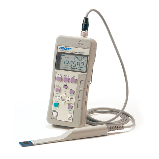
8230
Optical Power Meter
Operation Manual
FOE-8440171F01
MANUAL NUMBER
First printing March 30, 2007
ADC CORPORATION
C
2007
All rights reserved.
Printed in Japan
Table of
Contents
Previous
Page
Next
Page
1
2
3
4
5
Advertisement
Table of Contents
Need help?
Do you have a question about the 8230 and is the answer not in the manual?
Ask a question
Questions and answers
Related Manuals for ADCMT 8230
Accessories ADCMT 823B Series Operation Manual
Optical sensor (40 pages)
Measuring Instruments ADCMT 82311 Operation Manual
Optical power meter (120 pages)
Measuring Instruments ADCMT 8230E Operation Manual
Optical power meter (114 pages)
Measuring Instruments ADCMT 8250A Operation Manual
Optical power meter (142 pages)
Measuring Instruments ADCMT 8471 Operation Manual
Optical wavelength meter (118 pages)
Measuring Instruments ADCMT 8341 Operation Manual
Optical spectrum analyzer (242 pages)
Measuring Instruments ADCMT 5350 Operation Manual
Digital electrometer (200 pages)
Measuring Instruments ADCMT 12706A Operation Manual
Test fixture (32 pages)
Measuring Instruments ADCMT 6240B Operation Manual
Dc voltage current source/monitor (290 pages)
Measuring Instruments ADCMT 6166 Operation Manual
Dc voltage current source (274 pages)
Measuring Instruments ADCMT 12704A Operation Manual
Resistivity chamber (28 pages)
Measuring Instruments ADCMT 6243 Operation Manual
Dc voltage current source/monitor (296 pages)
Measuring Instruments ADCMT 12702A Operation Manual
Resistivity chamber (32 pages)
Measuring Instruments ADCMT 4601 I-V Meter Operation Manual
(236 pages)
Measuring Instruments ADCMT 6540 Operation Manual
4-channel dc voltage current source/monitor (264 pages)
This manual is also suitable for:
82311
82321
82312
82322
82313
82323
...
Show all
82311b
82321b
82312b
82322b
82313b
82323b
82314a
82324a
82314w
82314b
82324b
82314bw
Table of Contents
Print
Rename the bookmark
Delete bookmark?
Delete from my manuals?
Login
Sign In
OR
Sign in with Facebook
Sign in with Google
Upload manual
Upload from disk
Upload from URL


Need help?
Do you have a question about the 8230 and is the answer not in the manual?
Questions and answers