
Subscribe to Our Youtube Channel
Related Manuals for ADCMT 12706A


Summary of Contents for ADCMT 12706A
- Page 1 12706A Test Fixture OPERATION MANUAL Manual Number FOE-00000048A00 © 2009 ADC CORPORATION First printing March 31, 2009 All rights reserved. Printed in Japan...
-
Page 3: Table Of Contents
3.2.4 Connecting with the 8252 ....................3-7 3.3 Measurement ..........................3-8 3.4 Sample Program ........................... 3-9 3.5 Replacing the Test Socket ......................3-12 4. Specifications ....................4-1 Appendix ......................A1-1 A.1 Internal Connection ........................A1-1 A.2 12706A External View ......................A1-2 C-1*... - Page 5 12706A Test Fixture Operation Manual List of Illustrations Title Page 12706A Part Descriptions ................Attaching a Sample ..................Connecting with the 8340A ................. Connecting with the 8240 and the 6161 ............Replacing the Test Socket ................3-11 F-1*...
- Page 7 12706A Test Fixture Operation Manual List of Tables Title Page Parts with Limited Service Life ..............Connectable Measuring Instruments and Necessary Cables/Accessories..Test Socket Standard ..................3-10 T-1*...
-
Page 9: Introduction
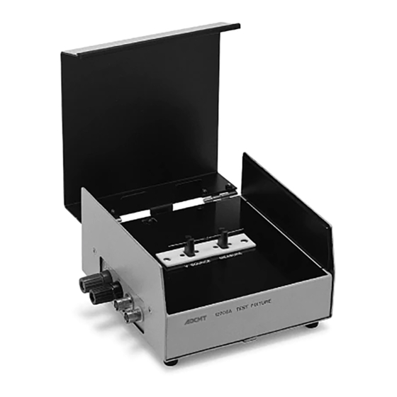
1. Introduction 1.1 Product Overview The 12706A test fixture is a sample box that connects to a measuring instrument such as 8340A, 8240 or 8252 to perform insulation resistance measurement and VSIM (voltage source current measurement) of capacitors and other electrical components. -
Page 10: Before Using The Product
The storage temperature range is from -25°C to +80°C. When not in use for a long time, cover the 12706A with a plastic sheet or put in a card- board box, and store it in a low humidity area away from direct sunlight. -
Page 11: Parts With Limited Service Life
1.2.3 Parts with Limited Service Life The 12706A use the following parts with limited service life. Check these parts by reference to the durability in the table. If any abnormality such as a con- tact failure is found, the parts need replacing. Please contact ADC Corporation or your sales representative. - Page 13 12706A Te est Fixture Operation M Manual 2 . Part Des scriptions 2. P Part Desc criptions Figure 2-1 12706A Pa art Descriptio 1. INPUT: t terminal for m measuremen Connects to the MEA ASURE of the e test socket [4].
-
Page 14: Part Descriptions
12706A Text Fixture Operation Manual 2 . Part Descriptions 3. LID SIGNAL: contact output by opening and closing the cover When the cover is closed, the terminals are short-circuited. When it is opened, the termin- als are open-circuited. Used to turn the applied voltage ON/OFF and to start measurement. -
Page 15: Methods Of Use
12706A Te est Fixture Operation M Manual Attaching a a Sample 3. M Methods of Use 3.1 A Attaching a Sample This section d describes the e procedure o of attaching a a sample to b be measured to the test so ocket. -
Page 16: Connecting To The Measuring Instruments
12706A Text Fixture Operation Manual 3.2 Connecting to the Measuring Instruments 3.2 Connecting to the Measuring Instruments This section describes the procedure of connecting the 12706A to measuring instruments. For the details of each instrument, refer to its operation manual. 3.2.1 Preparation before Connection The following table shows connectable instruments and necessary cables. -
Page 17: Connecting With The 8340A
(2) Connect the INPUT of the 8340A to the INPUT of the 12706A by using the TRI- AX-TRIAX cable (A01009 or A01239). (3) Connect the V SOURCE HI of the 8340A to the V SOURCE HI of the 12706A by using the banana-banana cable (A01240). - Page 18 12706A A Text Fixtu ure Operatio on Manual 3.2 Co onnecting to t the Measurin ng Instrumen Figure 3-2 Connecting with the 834 4 0A...
-
Page 19: Connecting With The 8240
This section describes the procedure of connecting the 12706A with the 8240. See Figure 3-3. Procedure: (1) Connect the INPUT of the 8240 to the INPUT of the 12706A by using the TRIAX-TRIAX cable (A01009). (2) Connect a voltage source such as the 6161 or 6144 to the V SOURCE (binding post) of the 12706A by using the banana-banana cable (A01240). - Page 20 12706A A Text Fixtu ure Operatio on Manual 3.2 Co onnecting to t the Measurin ng Instrumen Figure 3 3-3 Connec cting with th h e 8240 and t t he 6161...
-
Page 21: Connecting With The 8252
This section describes the procedure of connecting the 12706A with the 8252. Procedure: (1) Connect the INPUT of the 8252 to the INPUT of the 12706A by using the TRIAX-TRIAX cable (A01009). (2) Connect the HI and LO of the 8252 (short circuit between LO and GND) to the V SOURCE of the 12706A by using the output cable (A01044) and the banana adapter (A08531). -
Page 22: Measurement
(3) For the 8340A or 8252, set to voltage source current measurement (VSIM) or voltage source resistance measurement (VSRM). For the 8240, set to DC current measurement. (4) Closing the cover of the 12706A will turn on the applied voltage switch, allowing mea- surement. CAUTION 1. -
Page 23: Sample Program
12706A T Test Fixture Operation M Manual 3.4 Sample Program 3.4 S ample Pr rogram The followin ng shows a p program exa ample for m easurement by GPIB co ontrol using the NEC PC9801 serie es as persona al computer in Figure 3 -2. - Page 24 12706A Text Fixture Operation Manual 3.4 Sample Program Sample program descriptions Line No. Description Address 1 of the 8340A. (A variable does not start with a number. So, "R8340A" is used here.) Interface clear, remote enabled. Initialize the 8340A. Initialize the 8340A parameters.
- Page 25 12706A T T est Fixture Operation M Manual 3.4 Sample Program 3 3. Sample p p rogram resu ult 3-11...
-
Page 26: Replacing The Test Socket
12706A Text Fixture Operation Manual 3.5 Replacing the Test Socket 3.5 Replacing the Test Socket The test socket contact has durability of connecting/disconnecting 50,000 or more times. If contact failure due to abrasion occurs, the socket needs replacing. Please contact ADC Corpo- ration or your sales representative. - Page 27 12706A T Test Fixture Operation M Manual 3.5 Repl lacing the Te est Socket oldering iron Cabl Panel Test s socket Spring wa asher Test socke Flat he ead screw M2 2 x 12 Figure 3-4 Replacing th he Test Socke...
-
Page 29: Specifications
12706A Test Fixture Operation Manual 4. Specifications 4. Specifications Dielectric strength INPUT signal line – V SOURCE HI 1.5 kV DC for a minute INPUT signal line – Chassis 1.5 kV DC for a minute V SOURCE HI – Chassis 1.5 kV DC for a minute... -
Page 31: Appendix
12706A T T est Fixture Operation M Manual Appendix A1.1 Internal l Connect tion A1-1... -
Page 32: 12706A External View
12706A A Text Fixtu ure Operatio on Manual Appendix A1.2 12706A E External View A1-2*...
Need help?
Do you have a question about the 12706A and is the answer not in the manual?
Questions and answers