
Related Manuals for ADCMT 8250A


Summary of Contents for ADCMT 8250A
- Page 1 Cover 8250A Optical Power Meter Operation Manual FOE-8440218D01 MANUAL NUMBER First printing March 30, 2007 ADC CORPORATION 2007 All rights reserved. Printed in Japan...
- Page 3 Safety Summary Safety Summary To ensure thorough understanding of all functions and to ensure efficient use of this instrument, please read the manual carefully before using. Note that ADC Corporation (hereafter referred to as ADC) bears absolutely no re- sponsibility for the result of operations caused due to incorrect or inappropriate use of this instrument. If the equipment is used in a manner not specified by ADC, the protection provided by the equipment may be im- paired.
- Page 4 Safety Summary product. • When the product has ventilation outlets, do not stick or drop metal or easily flammable ob- jects into the ventilation outlets. • When using the product on a cart, fix it with belts to avoid its drop. •...
- Page 5 Safety Summary Main Parts with Limited Life Part name Life Unit power supply 5 years Fan motor 5 years Electrolytic capacitor 5 years LCD display 6 years LCD backlight 2.5 years Floppy disk drive 5 years Memory backup battery 5 years •...
- Page 6 Environmental Conditions This instrument should be only be used in an area which satisfies the following conditions: • An area free from corrosive gas • An area away from direct sunlight • A dust-free area • An area free from vibrations •...
- Page 7 Types of Power Cable Replace any references to the power cable type, according to the following table, with the appropriate power cable type for your country. Rating, color Model number Plug configuration Standards and length (Option number) PSE: Japan 125 V at 7 A Straight: A01402 Black...
- Page 9 PREFACE 8250A Optical Power Meter Operation Manual PREFACE This manual describes how to use the 8250A, its specifications, and how to use the 8250A by remote control. 1. Organization of this manual This manual consists of the following chapters. Safety Summary Read the safety instructions before operating this instrument.
- Page 10 8250A Optical Power Meter Operation Manual PREFACE 2. Notation • The panel keys are described in this manual as shown below. Panel key: In bold type Example:[ZERO], [RATIO/ dBr] 3. Trademarks and Registered Trademarks • Microsoft and Windows are trademarks or registered trademarks of Microsoft Corporation in the United States and other countries.
-
Page 11: Table Of Contents
TABLE OF CONTENTS 8250A Optical Power Meter Operation Manual TABLE OF CONTENTS INTRODUCTION ..................Product Overview ....................Accessories ......................Connectable Sensors ..................Optical Power Meter Software Revisions and Applicable Optical Sensors ..Options and Accessories ................... 1.5.1 Options ....................... Operating Environment .................. - Page 12 8250A Optical Power Meter Operation Manual Table of Contents 3.5.1 Setting the Preset Wavelength ..............3.5.2 Calling the Preset Wavelength ..............3-10 REMOTE CONTROL ................Selecting a Remote Interface ................4.1.1 Response to the *IDN? Command ............. GPIB ........................4.2.1 Overview ....................
- Page 13 8250A Optical Power Meter Operation Manual Table of Contents Current Measurement Calibration Point and Allowable Range ......Calibration Operation ..................Calibration Procedure ..................7.6.1 IV Offset Calibration .................. 7.6.2 Current Measurement Calibration .............. SPECIFICATIONS ..................8250A Specifications ..................8.1.1 Optical Power Meter Specifications ............
- Page 15 8250A Optical Power Meter Operation Manual LIST OF ILLUSTRATIONS Title Page Indication of the Set Power Supply Voltage ..............Connecting the Power Cable ..................... 1-11 Front View ........................Display Section ......................... Rear View ......................... Menu Map ......................... Menu Map in the Calibration Mode .................
- Page 17 8250A Optical Power Meter Operation Manual LIST OF TABLES Title Page Standard Accessories ......................Old and New Model Numbers of Optical Sensors ............List of Software Revisions Required for Optical Sensor Operations ....... Sensor Option ........................Relation Table between AC Power Supply Voltage and Indication of Set Power Supply Voltage ....................
-
Page 19: Introduction
High-performance optical sensors for the 8230 and 8230E series (abbreviated as the 823* series) and optical sensors for the TQ8210 and TQ8215 series (abbreviated as the 821* series) can be used in the 8250A. Various connector-removable-type 823* series optical sensors are provided so appropriate sensors can be selected according to the intended usage. -
Page 20: Connectable Sensors
8250A Optical Power Meter Operation Manual 1.3 Connectable Sensors Connectable Sensors Thin- and cylindrical-type 823x series sensors can be connected to this instrument. Functions of the sensors are categorized into general purpose, blue violet, high power, and 3 wavelengths. •... - Page 21 8250A Optical Power Meter Operation Manual 1.3 Connectable Sensors • 82323B The 82323B cylindrical-type optical sensor is available for attachment to test equipment, for measure- ment on an optical bench, or for optical fiber system measurement. Adapters to accommodate each op- tical connector are available.
-
Page 22: Old And New Model Numbers Of Optical Sensors
8250A Optical Power Meter Operation Manual 1.3 Connectable Sensors • 82017A The 82017A is a general-purpose, thin-type sensor used for the TQ8210 and TQ8215. Wavelengths ranging from 400 nm to 1100 nm can be measured and the calibration wavelength is 850 nm. The typical value stored in the optical power meter is used as wavelength sensitivity correction data. - Page 23 8250A Optical Power Meter Operation Manual 1.3 Connectable Sensors Table 1-2 Old and New Model Numbers of Optical Sensors (2 of 2) New model number Old model number Thin-type large-area three-wavelength optical sensor 82314BW 82314W Wavelength: 390 to 900 nm NOTE: The 823x series sensors cannot be used for the optical power meter TQ8210 or TQ8215.
-
Page 24: Optical Power Meter Software Revisions And Applicable Optical Sensors
A00 or later 82017A A00 or later 82015 *1 A00 or later 82018A *1 A00 or later *1 Currently discontinued. NOTE: If the software revision of the optical power meter 8250A is not applied, "Err 2" or "Err 3" is displayed. -
Page 25: Options And Accessories
8250A Optical Power Meter Operation Manual 1.5 Options and Accessories Options and Accessories 1.5.1 Options The following options are available for acquiring the wavelength sensitivity correction data or calibration data of the sensor. Specify the option when ordering. • Wavelength sensitivity correction option and calibration wavelength addition option... -
Page 26: Operating Environment
8250A Optical Power Meter Operation Manual 1.6 Operating Environment Operating Environment Use this instrument under the following conditions: ambient temperature from 0C to +40C and a non-con- densing relative humidity of 80% or less. Power Supply This section describes power requirements and how to connect the power cable. -
Page 27: Changing The Power Supply Voltage
8250A Optical Power Meter Operation Manual 1.7.2 Changing the Power Supply Voltage 1.7.2 Changing the Power Supply Voltage Remove the fuse holder assembly from the rear panel. Push both sides of the fuse holder assembly by using flathead screwdrivers ( and then pull it out ( Remove the power supply voltage selector from the fuse holder assembly. - Page 28 8250A Optical Power Meter Operation Manual 1.7.2 Changing the Power Supply Voltage Check that the correct power supply voltage is indicated in the window. 1-10...
-
Page 29: Connecting The Power Cable
8250A Optical Power Meter Operation Manual 1.7.3 Connecting the Power Cable 1.7.3 Connecting the Power Cable This instrument includes a three-core power cable with a grounding conductor. To prevent accidents caused by electric shocks, only use the included power cable and securely connect to the ground through a three-pin power outlet. -
Page 30: Precautions When Using This Instrument
8250A Optical Power Meter Operation Manual 1.8 Precautions when Using This Instrument Precautions when Using This Instrument • Avoid giving strong impacts to the instrument and sensor. The sensor contains delicate components such as photodiodes and other optical parts and is particularly sensitive to impacts and external forces. -
Page 31: Checking Operations
Press the [POWER] switch to turn on the power. All of the display are lit. The product name (8250A) is displayed in the measurement value display area, the software revision is displayed in the wavelength display area, and the con- nected sensor type (for example: “2314B”... -
Page 32: 1.10 Cleaning
8250A Optical Power Meter Operation Manual 1.10 Cleaning 1.10 Cleaning 1.10.1 Cleaning This Instrument Use a soft or damp cloth to clean this instrument. CAUTION: Do not allow water inside the instrument. Do not use an organic solvent such as benzene, toluene, xylene, acetone, or thinner for cleaning because they deform the plastic. -
Page 33: 1.11 How To Store And Transport This Instrument
8250A Optical Power Meter Operation Manual 1.11 How to Store and Transport This Instrument 1.11 How to Store and Transport This Instrument 1.11.1 Storage If this instrument is not used for a long time, do not store in the following environments to prevent damage, such as mechanical and chemical, to the instrument. -
Page 34: 1.14 Replacing Parts With Limited Life
8250A Optical Power Meter Operation Manual 1.14 Replacing Parts with Limited Life 1.14 Replacing Parts with Limited Life This instrument uses the following parts with limited life that are not listed in “Safety Summary.” Replace the parts listed below after their expected lifespan has expired. -
Page 35: 1.15 Product Disposal And Recycle
8250A Optical Power Meter Operation Manual 1.15 Product Disposal and Recycle 1.15 Product Disposal and Recycle This product should be disposed of according to the regulations and laws that are established by your country and municipality. When treating this product, separately collect components according to this chapter to prevent the spread of substances, which may be harmful to humans, and to protect the global environment. - Page 36 8250A Optical Power Meter Operation Manual 1.15 Product Disposal and Recycle Table 1-7 Disposal (2 of 2) Quantity Used/ Substance/Component Location Unit Component if full Not used configuration Components containing Not used - radioactive substances Electrolyte capacitors con- Not used - taining substances of con- cern (height >...
-
Page 37: Panel And Function Description
Press [ZERO] for 2 seconds after completely covering the optical sensor. The 8250A acquires the offset value while “ZERO” is displayed for approximately 4 seconds, and returns to the normal measure- ment mode. Press [ZERO] when turning on the power. If the sen- sor is not completely covered, “Err 1”... - Page 38 8250A Optical Power Meter Operation Manual 2.1.1 Function Description This key is used to enter the wavelength of the measurement light and to correct the wavelength sensitivity characteristics of the sensor. When [] is pressed, the least significant digit of the wavelength,...
- Page 39 8250A Optical Power Meter Operation Manual 2.1.1 Function Description 10. DOWN Changes the measurement range down when RANGE is set to MANUAL. 11. UP Changes the measurement range up when RANGE is set to MAN- UAL. 12. RATIO/dBr Displays the ratio (relative value) of each successive measured power to the power which is measured when “W”...
- Page 40 8250A Optical Power Meter Operation Manual 2.1.1 Function Description When setting the wavelength: Moves the digit of the input wavelength. In the menu mode: Moves the digit of the value or moves the cursor between items in each menu item.
-
Page 41: Display Section Description
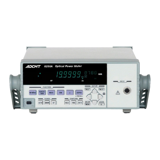
8250A Optical Power Meter Operation Manual 2.1.2 Display Section Description 2.1.2 Display Section Description Remote state Measurement value display section My address Wavelength display section Unit of wavelength Calibration mode ON MAX calculation ON Smoothing calculation ON CF calculation ON... -
Page 42: Rear Side
8250A Optical Power Meter Operation Manual 2.2 Rear Side Rear Side Figure 2-3 Rear View 22. LINE The connector for AC power supply The included power cable (A01402) is connected here. 23. Fuse holder assembly The power supply voltage can be selected from 100 V, 120 V, 220 V, and 240 V. -
Page 43: How To Perform Measurements
8250A Optical Power Meter Operation Manual 3. HOW TO PERFORM MEASUREMENTS HOW TO PERFORM MEASUREMENTS Menu Map Figure 3-1 Menu Map... -
Page 44: Menu Map In The Calibration Mode
8250A Optical Power Meter Operation Manual 3.1 Menu Map Figure 3-2 Menu Map in the Calibration Mode CAUTION: Even though if, after changing the setting of each item, the PREV/NEXT key is used to move to the next item, the setting is not saved. -
Page 45: Menu Description
8250A Optical Power Meter Operation Manual 3.2 Menu Description Menu Description Refer to 3.1, “Menu Map.” Smoothing count Sets the number of times that the smoothing calculation is per- formed. The setting range is from 0 to 100. (If 0 or 1 is set, the calculation is set to OFF.) - Page 46 8250A Optical Power Meter Operation Manual 3.2 Menu Description Preset wavelength Up to four frequently used wavelengths can be set. For more information, refer to 3.5, “Wavelength Preset.” Parameters loaded when the power turns on Selects parameters that are loaded when the power turns on from "P-OFF"...
-
Page 47: Measurement Procedure
Connect the sensor to the INPUT connector. 3.3.2 Setting the Wavelength Sets the wavelength sensitivity correction of the 8250A according to the wavelength which is used. 3.3.3 Zero Cancel Cancel the offset by covering the sensor with the sensor-cap or shading the sensor completely, and pressing the ZERO key of the 8250A for approximately 2 seconds. -
Page 48: Backing Up And Initializing Parameters
8250A Optical Power Meter Operation Manual 3.4 Backing Up and Initializing Parameters Backing Up and Initializing Parameters 3.4.1 Backing Up Parameters Because the parameters of this instrument are backed up (saved) in the built-in flash memory when the power turns off, the parameters are retained even if the power is off. -
Page 49: Outline Of The Parameter Backup
8250A Optical Power Meter Operation Manual 3.4.1 Backing Up Parameters Table 3-1 Initial Values of the Parameters and Backup (2 of 2) Saving or Value when shipping Parameter Backup loading (Initial value) parameters Common Interface (GPIB/USB) GPIB parameter GPIB address (USB-ID) -
Page 50: How To Initialize
8250A Optical Power Meter Operation Manual 3.4.2 How to Initialize 3.4.2 How to Initialize For more information on the parameters to be initialized, refer to Table 3-1. How to initialize all parameters to the factory set values. • Press the [POWER] switch while pressing the [UP] and [PREV] keys to turn on the power. -
Page 51: Wavelength Preset
8250A Optical Power Meter Operation Manual 3.5 Wavelength Preset Wavelength Preset Frequently used wavelengths can be set easily by registering the four wavelengths. The preset wavelength cannot be set and called by using the remote command. 3.5.1 Setting the Preset Wavelength The four wavelengths from No.0 to No.3 can be set. -
Page 52: Calling The Preset Wavelength
8250A Optical Power Meter Operation Manual 3.5.2 Calling the Preset Wavelength 3.5.2 Calling the Preset Wavelength The four preset wavelengths in the wavelength setting can be called and set. An example, in which a preset wavelength of 405 nm in No.1 is called, is shown below. See Figure 3-6. - Page 53 4.1.1 Response to the *IDN? Command This instrument has changed its model name from “ADCE8250A” to “8250A.” Accordingly, the response to the *IDN? command has also been changed. Note that an old model name response can also be set to maintain the compatibility with the application software.
- Page 54 8250A Optical Power Meter Operation Manual 4.1.1 Response to the *IDN? Command Specification of response to *IDN? New model name ADC Corp.,8250A ,XXXXXXXXX,YYYYY response XXXXXXXXX: Serial No. YYYYY: Revision No. Old model name ADC Corp.,ADCE8250A ,XXXXXXXXX,YYYYY response XXXXXXXXX: Serial No.
-
Page 55: Interface Functions
8250A Optical Power Meter Operation Manual 4.2 GPIB GPIB 4.2.1 Overview The automatic measurement system can be set up easily by using the GPIB (General Purpose Interface Bus) because setting measurement functions and parameters of this instrument and reading the mea- sured data can be controlled remotely. -
Page 56: Standard Bus Cable
8250A Optical Power Meter Operation Manual 4.2.2 Precautions in Use of GPIB 4.2.2 Precautions in Use of GPIB Do not use too long a bus cable to connect any instrument or controller. Ensure that the total cable length does not exceed 20 m. ADC CORPORATION uses the following cables as the standard bus cable. - Page 57 8250A Optical Power Meter Operation Manual 4.2.3 GPIB Setting 4.2.3 GPIB Setting The GPIB setting item and its initial setting when the instrument is shipped are shown below. Setting item Factory setting Header ON/OFF Addressable/Talk-Only Addressable Address GPIB address setting •...
- Page 58 8250A Optical Power Meter Operation Manual 4.3 USB 4.3.1 Overview A USB (Universal Serial Bus), which is compliant with the USB2.0 Full Speed standard, is included in this instrument as standard. By connecting multiple instruments to the USB ports on a personal computer, the functions of the instru- ments can be set, measured data can be read from the personal computer, and the automatic measurement system can be made up easily.
- Page 59 8250A Optical Power Meter Operation Manual 4.3.3 Precautions when Using USB 4.3.3 Precautions when Using USB Connect the connection cable to the USB connector (B type) on the rear panel of this instrument and the USB connector on the personal computer.
- Page 60 8250A Optical Power Meter Operation Manual 4.4 Measured Data Output Format Measured Data Output Format Measured data is output by using the ASCII strings shown below. CRLF Header Sub header Main header Number of String Description Priority characters Main header...
- Page 61 8250A Optical Power Meter Operation Manual 4.4 Measured Data Output Format Mantissa and Exponent Number of Number of Unit display Range Mantissa Exponent characters characters dd.dddd 20 nW E-09 ddd.ddd 200 nW E-09 dddd.dd 2000 nW E-09 20 W dd.dddd E-06 200 W...
- Page 62 8250A Optical Power Meter Operation Manual 4.4 Measured Data Output Format Number of displayed digits Number of Initial Number of Unit display Mantissa displayed value characters digits. 5 1/2 RATIO 4 1/2 3 1/2 ddd.ddd 5 1/2 (2,000 counts or more when W is displayed.)
- Page 63 8250A Optical Power Meter Operation Manual 4.4 Measured Data Output Format Block delimiter Initial Number of Block delimiter Setting command value characters CR+LF+EOI (GPIB) (USB) LF+EOI EOI is output only in GPIB. DL2 and DL3 cannot be set in USB.
-
Page 64: Status Register Structure
8250A Optical Power Meter Operation Manual 4.5 Status Register Status Register The status of the instrument can be checked from a personal computer because this instrument has a hierar- chical status register structure. The status register structure of this instrument is shown in Figure 4-1. -
Page 65: Status Byte Register
8250A Optical Power Meter Operation Manual 4.5 Status Register Table 4-3 Status Byte Register Name Description Not used Fixed to 0 Not used Fixed to 0 Not used Fixed to 0 ON: When any event of DESR occurs and DESR is set to 1, this bit Device Event Status is set to 1 if the corresponding bit of DESER is set to 1. -
Page 66: Device Event Status Register
8250A Optical Power Meter Operation Manual 4.5 Status Register Table 4-4 Device Event Status Register Name Description ON: This bit is set to 1 when the measurement is complete. End Of Measure OFF: This bit is set to 0 when the measurement starts.This bit is set to 0 when the measured data is read. -
Page 67: Standard Event Status Register
8250A Optical Power Meter Operation Manual 4.5 Status Register Table 4-5 Standard Event Status Register Name Description ON: This bit is set to 1 if all operations are complete after receiving Operation Complete the *OPC command. Not used Fixed to 0... -
Page 68: Error Register
8250A Optical Power Meter Operation Manual 4.5 Status Register Table 4-6 Error Register Description ON: This bit is set to 1 if the result of the ZERO execution contains an error. ON: This bit is set to 1 if no sensor is connected. - Page 69 8250A Optical Power Meter Operation Manual 4.6 Remote Command Remote Command 4.6.1 How to Set the Remote Command Remote command syntax • A command which consists of a header and no arguments <Example> *TRG (Measurement start) ZR (ZERO correction execution) •...
- Page 70 8250A Optical Power Meter Operation Manual 4.6.2 Remote Command List ted while the previous command is being executed, the command must wait until the execution of the previous command is complete. • Invalid commands cause errors and cannot be executed.
-
Page 71: Remote Command List
8250A Optical Power Meter Operation Manual 4.6.2 Remote Command List Table 4-7 Remote Command List (1 of 7) Initial value Availability Item Command Description Compa Calibra Power Factory GPIB Err2 tible tion default mode mode Measure- Display unit dBm unit display... - Page 72 8250A Optical Power Meter Operation Manual 4.6.2 Remote Command List Table 4-7 Remote Command List (2 of 7) Initial value Availability Item Command Description Compa Calibra Power Factory GPIB Err2 tible tion default mode mode Measure- Wavelength sen- WCF? Reads the sensitivity correction coeffi-...
- Page 73 8250A Optical Power Meter Operation Manual 4.6.2 Remote Command List Table 4-7 Remote Command List (3 of 7) Initial value Availability Item Command Description Compa Calibra Power Factory GPIB Err2 tible tion default mode mode Calcula- dBr calculation tion Available only when the dBm unit is displayed.
- Page 74 8250A Optical Power Meter Operation Manual 4.6.2 Remote Command List Table 4-7 Remote Command List (4 of 7) Initial value Availability Item Command Description Compa Calibra Power Factory GPIB Err2 tible tion default mode mode Remote Permission of SRQ transmitting...
- Page 75 8250A Optical Power Meter Operation Manual 4.6.2 Remote Command List Table 4-7 Remote Command List (5 of 7) Initial value Availability Item Command Description Compa Calibra Power Factory GPIB Err2 tible tion default mode mode System Instrument *IDN? Query command which inquires for the information instrumen information.
- Page 76 8250A Optical Power Meter Operation Manual 4.6.2 Remote Command List Table 4-7 Remote Command List (6 of 7) Initial value Availability Item Command Description Compa Calibra Power Factory GPIB Err2 tible tion default mode mode System User parameter *SAV0 Saves the setting parameters in area [0] of the nonvolatile memory.
- Page 77 8250A Optical Power Meter Operation Manual 4.6.2 Remote Command List Table 4-7 Remote Command List (7 of 7) Initial value Availability Item Command Description Compa Calibra Power Factory GPIB Err2 tible tion default mode mode data: Setting range: 999.999E-3ERR Instru- Calibration exe- data...
- Page 78 8250A Optical Power Meter Operation Manual 4.6.3 TQ8215 Compatibility 4.6.3 TQ8215 Compatibility By using "TQ8215 compatible mode", this instrument and the existing model TQ8215 are compatible in the GPIB remote level. CAUTION: The TQ8215 compatible mode is a function to use user programs, which are used in the TQ8215, in this instrument with minimum modification.
-
Page 79: Commands Used In The Tq8215 But Cannot Be Used In This Instrument
8250A Optical Power Meter Operation Manual 4.6.3 TQ8215 Compatibility Commands that are used in the TQ8215 but cannot be used in this instrument Commands, which are used in the TQ8215 but cannot be used (no functions) in this instrument re- gardless of the mode, are shown below. - Page 80 8250A Optical Power Meter Operation Manual 4.6.3 TQ8215 Compatibility Table 4-8 Commands Used in the TQ8215 but Cannot Be Used in this Instrument (2 of 2) Function Command Parameter setting P1, range, and calculation mode P2, range, and calculation mode...
-
Page 81: Commands Specific To The Tq8215 Compatible Mode
8250A Optical Power Meter Operation Manual 4.6.3 TQ8215 Compatibility Commands that are specific to the TQ8215 compatible mode Commands, which are valid only in the TQ8215 compatible mode, and commands, whose functions are changed in this mode, are shown below. - Page 82 Sets to the CFMPY mode. • CFS1 (the same as the CF calcula- tion ON) • In the 8250A, the wavelength cor- rection cannot be set to OFF. There- fore, by setting the wavelength to the default value, the same result can be acquired.
- Page 83 8250A Optical Power Meter Operation Manual 4.6.3 TQ8215 Compatibility Table 4-9 Commands Specific to the TQ8215 Compatible Mode (3 of 3) Availability Comp Calibr Item Command Description *RST GPIB atible ation Err2 mode mode Parame- Parameter set- P5,range, Specifies the range and unit in the opti-...
-
Page 84: Commands That Cannot Be Used In The Tq8215 Compatible Mode
8250A Optical Power Meter Operation Manual 4.6.3 TQ8215 Compatibility Commands that cannot be used in the TQ8215 compatible mode Commands, which cannot be used in the TQ8215 compatible mode, are shown below. A command error occurs if these commands are executed in the TQ8215 compatible mode. - Page 85 8250A Optical Power Meter Operation Manual 4.6.3 TQ8215 Compatibility Measured data output format in the TQ8215 compatible mode E CRLF Header Sub header Main header Number of String Description characters Main header Measurement unit: dBm Measured value after the dBr calculation...
- Page 86 8250A Optical Power Meter Operation Manual 4.6.3 TQ8215 Compatibility Mantissa and Exponent Number of Number of Unit display Range Mantissa Exponent characters characters dd.ddd 20 nW ddd.dd 200 nW d.dddd 2000 nW 20 W dd.ddd 200 W ddd.dd 2000 W d.dddd...
- Page 87 8250A Optical Power Meter Operation Manual 4.6.3 TQ8215 Compatibility Block delimiter Number of Initial Block delimiter Setting command characters value CR+LF+EOI (GPIB) (USB) LF+EOI EOI is output only in GPIB. DL2 and DL3 cannot be set in USB. Mantissa and exponent in the over range and under range...
-
Page 88: Status Register Structure In The Tq8215 Compatible Mode
8250A Optical Power Meter Operation Manual 4.6.3 TQ8215 Compatibility Status register in the TQ8215 compatible mode Figure 4-2 Status Register Structure in the TQ8215 Compatible Mode 4-36... -
Page 89: Differences With The 8230 In The Remote Level
8250A Optical Power Meter Operation Manual 4.6.4 8230 Compatibility 4.6.4 8230 Compatibility This instrument and the existing model 8230 are compatible in the remote level. Note differences shown in Table 4-11 between this instrument and the 8230. Table 4-11 Differences with the 8230 in the Remote Level (1 of 2) - Page 90 8250A Optical Power Meter Operation Manual 4.6.4 8230 Compatibility Table 4-11 Differences with the 8230 in the Remote Level (2 of 2) 8250A 8230 Function Command Description Command Description Initialization Device clear Sets the conditions when the • Initializes the remote input power is turned on.
-
Page 91: Measurement Image 1 (Gpib)
Option Explicit ' Registers the subroutine for the command button on the sheet. Sub Sample1_Click() ' Declares the variable of the GPIB address of the 8250A. Dim GP_ADR As Integer ' Declares the variable of the device descriptor. Dim opm As Integer ' Declares the variable of the buffer used for receiving the GPIB data. -
Page 92: Measurement Image 2 (Gpib)
End Sub Example 2 Triggers the measurement in the sampling HOLD mode, detects the measurement end by using the status byte, and reads the measured data from the 8250A. Set the GPIB address of the 8250A to 1. Figure 4-4 Measurement Image 2 (GPIB) Program list ' All variables are clearly declared. - Page 93 8250A Optical Power Meter Operation Manual 4.7.1 GPIB Sample Programs Call ibwrt(opm, "*TRG" & vbCrLf) ' Triggers. Call ibwrt(opm, "*STB?" & vbCrLf) ' Inquires the status byte. ' Reads the status byte. Call ibrd(opm, dt) ' Performs the AND operation in bit4 (MAV).
-
Page 94: Measurement Image 1 (Usb)
MS-EXCEL2000 VBA Example 1 Acquires the measured data for the specified number of times. Press [ENTER] for the speci- fied number of times after pressing [START]. Set USB.ID of the 8250A to 1. Figure 4-5 Measurement Image 1 (USB) Program list ' All variables are clearly declared. - Page 95 8250A Optical Power Meter Operation Manual 4.7.2 USB Sample Programs ' Sets the measurement count to 10. mcnt = 10 ' USB initialization, time-out: 10 seconds ret = ausb_start(10) ' If the USB initialization is performed incorrectly, If ret <> OK Then MsgBox "USB initialization error", vbExclamation...
-
Page 96: Measurement Image 2 (Usb)
' Sets the flag of the ENTER input button to ON. enterF = 1 End Sub Example 2 Acquires the measured data from the connected two set of the 8250A. Set USB.ID of each 8250A to 1 and 2. Figure 4-6 Measurement Image 2 (USB) Program list ' All variables are clearly declared. - Page 97 8250A Optical Power Meter Operation Manual 4.7.2 USB Sample Programs ' If the device is opened incorrectly, If ret <> OK Then MsgBox "USB_ID 1 OPEN error", vbExclamation GoTo err_exit End If ' Waits until the OPM whose USB_ID is set to 1 opens (100 ms).
- Page 98 8250A Optical Power Meter Operation Manual 4.7.2 USB Sample Programs ' If the USB terminates incorrectly, If ret <> OK Then MsgBox "USB end error", vbExclamation End If End Sub 4-46...
-
Page 99: Relationship Between The Current Range And The Full-Scale Voltage Output From
8250A Optical Power Meter Operation Manual 5. TECHNICAL NOTES TECHNICAL NOTES Principles of Measurement Figure 5-1 shows a block diagram of this instrument. When light falls on the photodiode in the sensor, the photo-electric current, which is generated, is converted into voltage through the IV converter, amplified, and then digitized through the AD converter as measured data. -
Page 100: Block Diagram Of The 8250A
5.2 Analog Out 823* series sensor Fluorescent display tube Photodiode bias circuit Nonvolatile memory Wavelength sensitivity data Power calibration data Power Sensor ID supply circuit 821* series sensor VR for the power calibration Sensor ID Figure 5-1 Block Diagram of the 8250A... -
Page 101: Wavelength Sensitivity Characteristics And Power Calibration Of The Sensor
8250A Optical Power Meter Operation Manual 5.3 Optical Power Calibration and Wavelength Sensitivity Correction Optical Power Calibration and Wavelength Sensitivity Correction Characteristics of sensor photodiodes include varying sensitivity for individual photodiodes and wavelength- dependent sensitivity. This instrument guarantees accuracy over a wide range of wavelengths by using both the power calibration at the calibration wavelength and the wavelength sensitivity correction over a wide range of wavelengths. -
Page 102: Calibration Wavelength Selection Function
8250A Optical Power Meter Operation Manual 5.4 Calibration Wavelength Selection Function Calibration Wavelength Selection Function An optional function of this instrument allows power calibration over multiple wavelengths. If a measurement is performed at each calibration wavelength by using this function, the accuracy obtained by using this function is much higher than the accuracy obtained by using the wavelength sensitivity correc- tion function. -
Page 103: Cable And Others Required For Performance Test
8250A Optical Power Meter Operation Manual 6. PERFORMANCE TEST PERFORMANCE TEST This chapter describes the procedures used to check whether this instrument (8250A) and the sensors (82311B, 82312B, 82313B, 82321B, 82322B, 82323B, 82314B, 82314BW, and 82324B) operate correctly within the guaranteed accuracy. -
Page 104: Connection Diagram For The Performance Test
Warm-up time: 5 minutes or more The performance of this instrument (8250A) can be checked by performing a current measurement test. This instrument allows the different internal measurement path (sensor series path) according to the sensor series (823* or 821* series) connected to this instrument. Because the specifications are different between each sensor series, switch the path and perform the test. -
Page 105: Current Range Accuracy Specifications
8250A Optical Power Meter Operation Manual 6.1.2 How to Test Remove the sensor and connect this instrument to the current generator (hereafter called VIG) through the TRIAX-12pin conversion adapter A as shown in Figure 6-1. Open the input and measure the current at ZERO in all ranges. Use the [UP] and [DOWN] keys to select a range. - Page 106 8250A Optical Power Meter Operation Manual 6.1.2 How to Test Table 6-3 Current Range Accuracy Specifications (2 of 2) Specification Measurement RANGE Setting value point 823* series path 821* series path 200 A 70.0 nA 70.0 nA ZERO 0 A (Open) 190 A...
-
Page 107: Equipment Required For Evaluating Optical Sensors
8250A Optical Power Meter Operation Manual 6.2 Performance Test of the Optical Sensors Performance Test of the Optical Sensors To calibrate the optical sensors, the light source, optical fiber, and standard optical power meter, all of which satisfy the specifications described below, as well as a measuring environment with little or no vibration, at a temperature of +23C 5C, and a temperature change of 1C are required. -
Page 108: Connection Diagram For The Optical Sensor Performance Test
8250A Optical Power Meter Operation Manual 6.2.1 How to Connect Instruments 6.2.1 How to Connect Instruments Sensor for the standard optical power meter LD light source Optical fiber FC adapter Optical sensor to be tested Optical power meter 8250A/8230 Figure 6-2 Connection Diagram for the Optical Sensor Performance Test 6.2.2... - Page 109 Ensure that the light source and optical power meter are ready and in the stable state. Set of the optical power meter (8250A or 8230), which is connected to a sensor to be tested, to the calibration wavelength. Ensure that c is displayed.
-
Page 111: Cable, Adapter, And Others Required For Calibration
7. CALIBRATION CALIBRATION This chapter describes how to calibrate the 8250A optical power meter for use within the specified accuracy. For more information on calibrating the sensors, contact ADC CORPORATION. To use this instrument within the specified accuracy, this instrument should be calibrated once a year. If asking ADC CORPORA- TION to calibrate the 8250A, contact ADC CORPORATION or a sales representative. - Page 112 8250A Optical Power Meter Operation Manual 7.2 Precautions Precautions Perform the calibration in an area free from dust, vibration, and noise, and under the following environ- mental conditions: +23C 5C and temperature change of 1C Temperature: Relative humidity: 70% or less This instrument requires a warm-up time of 5 minutes or more.
-
Page 113: Connection Diagram For The Iv Offset Calibration
8250A Optical Power Meter Operation Manual 7.3 How to Connect Instruments How to Connect Instruments Connecting the instruments for the IV offset calibration Input open TRIAX-12pin Connection for the zero calibration conversion adapter A TRIAX-12pin Connection for the full-scale calibration... -
Page 114: Calibration Point And Allowable Range
8250A Optical Power Meter Operation Manual 7.4 Current Measurement Calibration Point and Allowable Range Current Measurement Calibration Point and Allowable Range To perform the calibration, use an instrument, which satisfies the required accuracy described in Section 7.1, “Instrument, Cable, and Others Required for Calibration”, and adjust the current at the calibration point to within the allowable range shown in the table below. -
Page 115: Calibration Flow
8250A Optical Power Meter Operation Manual 7.5 Calibration Operation Calibration Operation The calibration of this instrument cannot be performed by key operations. Perform the calibration by using the remote commands through the USB or GPIB. For more information on remote commands, refer to calibration items in Section 4.4, “Measured Data Output Format.”... - Page 116 8250A Optical Power Meter Operation Manual 7.5 Calibration Operation Calibration mode: CAL1 Enters the calibration mode. Input open Zero calibration XIVC0 Calibration is complete. Connect the 1 k resistor. Full-scale calibration XIVC1 Calibration is incomplete. Judgment Calibration is complete. Calibration error...
-
Page 117: Current Measurement Calibration Flow
8250A Optical Power Meter Operation Manual 7.5 Calibration Operation Calibration point Range Command Zero Full scale 20 nA OPEN 19.0000 nA Calibration mode: CAL11 200 nA OPEN 190.000 nA 2000 nA OPEN 1900.00 nA 20 A 19.0000 A OPEN All data initialization: XINI0 200 A... -
Page 118: Current Measurement Calibration
8250A Optical Power Meter Operation Manual 7.6 Calibration Procedure Calibration Procedure This section describes the calibration procedure. This instrument enters the calibration mode when the CAL1 command is trans- mitted. In reference to Section 7.3, “How to Connect Instruments”, connect the instru- ments. - Page 119 8250A Optical Power Meter Operation Manual 7.6.2 Current Measurement Calibration Perform the zero calibration in all ranges. Set a range. 20 nA: XR4 200 nA: XR5 2 A: 20 A: XR7 200 A: XR8 2 mA: XR9 20 mA: XR10 50 mA: XR11 Open the input.(0 A)
- Page 121 8250A Optical Power Meter Operation Manual 8. SPECIFICATIONS SPECIFICATIONS 8250A Specifications The accuracy in all specifications is guaranteed for one year at a temperature of +23C 5C and a relative humidity of 70% or less. 8.1.1 Optical Power Meter Specifications Display resolution: 0.1 pW (in the W unit display), 0.001 dB (in the dBm unit display)
- Page 122 8250A Optical Power Meter Operation Manual 8.1.2 General Specifications the power meter, is used. Calibration Wavelength Selection Function: This function operates when the "Calibration wavelength addition" option is set in the sensor. "Measurement accuracy at the calibration wavelength" can be applied at mul- tiple wavelengths.
-
Page 123: Standard Accessories
8250A Optical Power Meter Operation Manual 8.1.3 Standard Accessories Power supply: 100/120/220/240 VAC, Power supply frequency; 50/60 Hz Power consumption: 15 VA or less Approx. 212 (Width) 88 (Height) 340 (Depth) mm External dimensions: Mass: 2.9 kg or less 8.1.3... - Page 124 8250A Optical Power Meter Operation Manual 8.2 Optical Sensor Specifications Optical Sensor Specifications 8.2.1 Sensor Specifications (Sold Separately) 823x series 82311/82311B 82312/82312B 82313/82313B Model (General-purpose) (For blue-violet light) (For high power light) Wavelength range 390 to 1100 nm 390 to 450 nm...
- Page 125 8250A Optical Power Meter Operation Manual 8.2.1 Sensor Specifications (Sold Separately) Model 82314A/82314B (For 3 wavelengths) Wavelength range 900 nm Wavelength 405 nm 650 nm 780 nm Display in dBm -50 to +20 dBm Power range Display in W 10 nW...
- Page 126 8250A Optical Power Meter Operation Manual 8.2.1 Sensor Specifications (Sold Separately) Item Specification Model 82324A/82324B (For 3 wavelengths) Wavelength range 900 nm Wavelength 405 nm 650 nm 780 nm Display in dBm -50 to +20 dBm Power range Display in W...
- Page 127 8250A Optical Power Meter Operation Manual 8.2.2 Wavelength Sensitivity Correction Option and Additional Calibration Wavelength Option 8.2.2 Wavelength Sensitivity Correction Option and Additional Calibration Wavelength Option Wavelength sensitivity correction option: The wavelength sensitivity of each sensor is measured and corrected when calibrating.
-
Page 129: Problem And Solution
8250A Optical Power Meter Operation Manual APPENDIX APPENDIX A.1 Trouble Shooting (Before Asking for Repair) If a problem occurs in this instrument, check the following table to solve the problem before asking ADC CORPORATION for repair. If the problem persists after the relevant solution is performed, contact ADC CORPORATION or a sales representative. -
Page 130: Self-Test Item List
8250A Optical Power Meter Operation Manual A.2 Error Messages A.2 Error Messages This section describes the error messages that are displayed while this instrument is used. Table A-2 Self-Test Item List When an error Test method occurs. Test item When... -
Page 131: Error Messages
8250A Optical Power Meter Operation Manual A.2 Error Messages Table A-3 Error Messages Error generation timing Buzzer Test when Display Error description Display time Solution Other turning on timings the power. Err 1 "OL" is generated in any range While Approx. -
Page 132: Causes Of The Generated Calibration Errors
8250A Optical Power Meter Operation Manual A.2 Error Messages Table A-4 Causes of the Generated Calibration Errors Cause Command Display Status Remarks The I/V offset calibration is not con- XIVC Err 10 ERR Bit7 ON vergent. The difference between the VIG gen-... - Page 133 8250A Optical Power Meter Operation Manual A.3 Remote Execution Time (Typical Value) A.3 Remote Execution Time (Typical Value) Execution time measurement conditions Computer: OPTIPLEX GX270 manufactured by DELL GPIB hardware: PCI-GPIB manufactured by NATIONAL INSTRUMENTS GPIB driver: Niglobal.bas, Vbib-32.bas (Included software in PCI-GPIB)
- Page 135 DIMENSIONAL OUTLINE DRAWING EXT-1...
- Page 136 EXT-2...
- Page 137 EXT-3...
- Page 138 EXT-4...
- Page 139 ALPHABETICAL INDEX ALPHABETICAL INDEX 8250A Optical Power Meter Operation Manual ALPHABETICAL INDEX [Numerics] GPIB Sample Programs ......4-39 GPIB Setting ........... 4-5 8230 Compatibility ......... 4-37 8250A Specifications ......8-1 How to Connect Instruments ....6-2, 6-6, Accessories ..........1-1 How to Initialize ........
- Page 140 8250A Optical Power Meter Operation Manual Alphabetical Index Product Disposal and Recycle ....1-17 Product Overview ........1-1 Reading the Display ........ 3-5 Rear Side ..........2-6 Remote Command ........4-17 Remote Command List ......4-18 REMOTE CONTROL ......4-1 Remote Execution Time (Typical Value) A-5 Replacing Parts with Limited Life ..
- Page 141 IMPORTANT INFORMATION FOR ADC CORPORATION SOFTWARE PLEASE READ CAREFULLY: This is an important notice for the software defined herein. Computer programs including any additions, modifications and updates thereof, operation manuals, and related materials provided by ADC CORPORATION (hereafter referred to as "SOFTWARE"), included in or used with hardware produced by ADC CORPORATION (hereafter referred to as "PRODUCTS").
- Page 142 5. EXCEPT TO THE EXTENT EXPRESSLY PROVIDED HEREIN, ADC CORPORATION HEREBY EXPRESSLY DISCLAIMS, AND THE PURCHASER HEREBY WAIVES, ALL WARRANTIES, WHETHER EXPRESS OR IMPLIED, STATUTORY OR OTHERWISE, INCLUDING, WITHOUT LIMITATION, (A) ANY WARRANTY OF MERCHANTABILITY OR FITNESS FOR A PARTICULAR PURPOSE AND (B) ANY WARRANTY OR REPRESENTATION AS TO THE VALIDITY, SCOPE, EFFECTIVENESS OR USEFULNESS OF ANY TECHNOLOGY OR ANY INVENTION.
Need help?
Do you have a question about the 8250A and is the answer not in the manual?
Questions and answers