
Related Manuals for ADCMT 8341


Summary of Contents for ADCMT 8341
- Page 1 Cover 8341 Optical Spectrum Analyzer Operation Manual FOE-8440118D01 MANUAL NUMBER First printing August 1, 2003 ADC CORPORATION 2003 All rights reserved. Printed in Japan...
- Page 3 Safety Summary Safety Summary To ensure thorough understanding of all functions and to ensure efficient use of this instrument, please read the manual carefully before using. Note that ADC Corporation (hereafter referred to as ADC) bears absolutely no re- sponsibility for the result of operations caused due to incorrect or inappropriate use of this instrument. If the equipment is used in a manner not specified by ADC, the protection provided by the equipment may be im- paired.
- Page 4 Safety Summary product. • When the product has ventilation outlets, do not stick or drop metal or easily flammable ob- jects into the ventilation outlets. • When using the product on a cart, fix it with belts to avoid its drop. •...
- Page 5 Safety Summary Main Parts with Limited Life Part name Life Unit power supply 5 years Fan motor 5 years Electrolytic capacitor 5 years LCD display 6 years LCD backlight 2.5 years Floppy disk drive 5 years Memory backup battery 5 years •...
- Page 6 Environmental Conditions This instrument should be only be used in an area which satisfies the following conditions: • An area free from corrosive gas • An area away from direct sunlight • A dust-free area • An area free from vibrations •...
- Page 7 Types of Power Cable Replace any references to the power cable type, according to the following table, with the appropriate power cable type for your country. Rating, color Model number Plug configuration Standards and length (Option number) PSE: Japan 125 V at 7 A Straight: A01402 Black...
- Page 9 8341 Optical Spectrum Analyzer Operation Manual PREFACE This manual provides the information necessary to check functionality, operate and program the 8341 Optical Spectrum Analyzer. Be sure to read this manual carefully in order to use the Optical Spectrum Analyzer safely.
- Page 10 8341 Optical Spectrum Analyzer Operation Manual PREFACE 2. Key notations in this manual • Typeface conventions used in this manual. Panel keys: In bold type Example: APPLICATION, SETUP Soft buttons: In bold and italic type Example: TREND, PRESET • When a series of key operations are described using a comma between two keys.
-
Page 11: Table Of Contents
Cleaning ...................... 1-14 1.6.2 Storing ......................1-14 1.6.3 Description and Handling Cautions for the Light Input Part of the 8341 .. 1-15 1.6.3.1 Operation and Cleaning Methods for the Light Input Part ......1-15 1.6.3.2 Operational Care and Replacement Methods for the Optical Connector Adapter ....................... - Page 12 8341 Optical Spectrum Analyzer Operation Manual Table of Contents Basic Operations ....................2.2.1 Operation Device ..................2.2.2 Menu Operation Methods ................2.2.3 Inputting Data ..................... 2-15 2.2.3.1 Inputting Data Into the Input Window ............2-15 2.2.3.2 Inputting Data into a Dialog Box ...............
- Page 13 8341 Optical Spectrum Analyzer Operation Manual Table of Contents 2.9.7 Updating the Software (REVISION UP) ........... 2-56 2.9.8 Setting the Network (NETWORK SETTING) ........... 2-57 2.9.9 Setting the Network Speed (NETWORK SPEED) ........2-59 2.10 Copying and Deleting Files (FILE MANAGER) ..........
- Page 14 8341 Optical Spectrum Analyzer Operation Manual Table of Contents 5.3.3 Message Exchange Protocol ............... 5.3.3.1 GPIB Buffers ....................5.3.3.2 IEEE488.2-1987 Command Mode ............. 5-10 Command Syntax ....................5-11 5.4.1 IEEE488.2-1987 Command Mode ............. 5-11 5.4.1.1 Command Syntax ..................5-11 5.4.1.2 Data Formats ....................
- Page 15 8341 Optical Spectrum Analyzer Operation Manual Table of Contents APPENDIX ......................... Trouble Shooting ....................SAVE Data Contents ..................Error Message ....................DIMENSIONAL OUTLINE DRAWING ............EXT-1 ALPHABETICAL INDEX ..................
- Page 17 8341 Optical Spectrum Analyzer Operation Manual LIST OF ILLUSTRATIONS Title Page Operating Environment ..................... Replacing the Power Fuse ....................Power Cable ........................Attaching a Ferrite Core ....................1-10 The Power Cable Connection ................... 1-11 POWER Switch ........................ 1-12 Initial Measurement Screen ....................
- Page 18 8341 Optical Spectrum Analyzer Operation Manual List of Illustrations Title Page 2-38 2nd-peak Measurement Screen ..................2-49 2-39 Normal Completion of the Self-test .................. 2-51 2-40 Error Completion of the Self -test ..................2-52 2-41 LABEL Setting ......................... 2-53 2-42 System Information ......................
- Page 19 8341 Optical Spectrum Analyzer Operation Manual List of Illustrations Title Page Structure of the Status Byte Register ................5-20 Inside Unit Outline Block Diagram .................. Peak Waveform and Cursor Display ................Total Power Calculation ....................Wavelength Accuracy Test Equipment Connection ............
- Page 21 8341 Optical Spectrum Analyzer Operation Manual LIST OF TABLES Title Page Standard Accessories List ....................Power Supply Specifications .................... RANGE and Measurement Wavelength Bandwidth ............2-18 Resolution Setting (RESOLN), Wavelength Resolution, Peak Wavelength Resolution, and COHERENCE Length ....................2-25 GPIB Interface Functions ....................
-
Page 23: Introduction
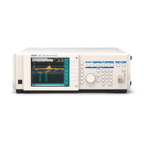
8341 for the first time. Product Description The 8341 is an optical spectrum analyzer which is capable of analyzing short wavelengths from 350 nm to 1000 nm. The 8341 can analyze the coherence because it adopts the Michelson interferometer method. -
Page 24: Accessories
1.2 Accessories Accessories The table below lists the standard accessories shipped with the 8341. If any of the accessories are damaged or missing, contact the nearest ADC CORPORATION Field Office or representative. Additional accessories should be referred to by model name when ordered. -
Page 25: Operating Environment
(toward the front) of the 8341. Never block these vents. The resulting internal temperature rise will affect measurement accuracy. Keep the rear panel 10 centimeters away from the wall. In addition, do not attempt to use the 8341 when it is standing on its rear panel or on either side panel. -
Page 26: 1.3.2 Power Supply Specifications
The power supply specifications of the 8341 are listed in Table 1-2. CAUTION: To prevent damage, operate the 8341 within the specified input voltage and frequency ranges. Maximum power consumption is 150 VA. Use a suitable power supply. Use a power cable compatible with the supply voltage (refer to “Safety Summary”). -
Page 27: Power Fuse
1.3.3 Power Fuse CAUTION: When a fuse blows, there may be some problem with the 8341. Contact a sales representative before replacing the fuse. For fire prevention, use only fuses with the same rating and same type. The power fuse is placed in the fuse holder which is mounted on the rear panel. -
Page 28: 1.3.4 Power Cable
8341 Optical Spectrum Analyzer Operation Manual 1.3.4 Power Cable 1.3.4 Power Cable CAUTION: Use a power cable rated for the voltage in question. Be sure however to use a power cable conforming to safety standards of your nation when using a product overseas (refer to “Safety Summary”). -
Page 29: Safety Precautions When Using The 8341
Life Span of the Backup Lithium Battery The life span of the 8341’s backup lithium battery is three years. When the service life of the battery has ended, an error message is displayed when the 8341 power is turned on, and the startup is terminated. We recommend that the backup lithium battery be replaced early enough to prevent this situation from arising. -
Page 30: Front Feet
1.4.5 Front Feet Four feet (two at the front and two at the rear) are attached to the bottom of the 8341. The front feet can be extended so that the front of the instrument is raised. The extensions may wear out over time. If this occurs, contact the nearest ADC CORPORATION Field Office or representative for information on how to replace them. -
Page 31: Notes For Safe Use Of The 8341
The 8341 uses Windows XP. Since the measurements are enabled using Windows applications, do not modify the Windows environment unless specifically instructed to do so in this manual. The 8341 is not a data-processing unit and can only be used as described in this manual. -
Page 32: Emi And Ems Compliancy
Electromagnetic Interference The 8341 may cause electromagnetic interference and effect television and radio reception. If the 8341 power is turned off and the electromagnetic interference is reduced, then the 8341 has caused the problem. Electromagnetic interference may be prevented by doing the following: •... -
Page 33: Operations Check
8341 Optical Spectrum Analyzer Operation Manual 1.5 Operations Check Operations Check When using the unit for the first time, confirm that the unit operates normally by completing the processes explained in this section. 1.5.1 Turning the Power On Install the unit on a stable, flat surface. -
Page 34: Power Switch
Do not press any buttons until the measurement screen is displayed. If no signal is input and high-sensitivity is set to the 8341, the 633 nm internal He- Ne laser signal may be observed at around the -60 dBm level. -
Page 35: Turning Off The Unit
The termination process is executed and the power is automatically turned off. CAUTION: Follow the procedure above to turn off the 8341. If the unit is turned off incorrectly, a warning message is displayed the next time the unit is turned on. -
Page 36: Cleaning, Storing And Transporting The 8341
Storing Store the 8341 in an area which has a temperature from -10 C to +50 C. If you plan to store the 8341 for a long period (more than 90 days), put the 8341 in a vapor-barrier bag with a drying agent and store the 8341 in a dust-free location out of direct sunlight. -
Page 37: Description And Handling Cautions For The Light Input Part Of The 8341
CAUTION: Operating the 8341 without cleaning the optical input or incorrectly aligning the optical fiber with the optical input may cause an error in the measured result. Operating with a dirty light input part harms the ferrule surface. -
Page 38: Operational Care And Replacement Methods For The Optical Connector Adapter
8341 Optical Spectrum Analyzer Operation Manual 1.6.3 Description and Handling Cautions for the Light Input Part of the 8341 1.6.3.2 Operational Care and Replacement Methods for the Optical Connector Adapter When inserting the light fiber connector into the light input part or taking it out, move slowly and carefully, making sure the connector is kept straight. -
Page 39: Transporting
8341 Optical Spectrum Analyzer Operation Manual 1.6.4 Transporting 1.6.4 Transporting When you ship the analyzer, use the original container and packing material. If the original packaging is not available, use the following repackaging guidelines: Packing Procedure To allow for cushioning, use a corrugated cardboard container that is at least 15 centimeters larger than those of the analyzer. -
Page 40: When Disposing The 8341
Back up lithium battery 3 years The 8341 is equipped with a function, which displays the elapsed time from when the 8341 was switched on, and a function, which monitors the He-Ne laser level. For more information on the elapsed time, refer to 4.3.7, “SYSTEM Button.”... -
Page 41: Operation
8341 Optical Spectrum Analyzer Operation Manual 2. OPERATION OPERATION This chapter describes the front and rear panel elements as well as the basic operations of the unit. Panel Descriptions This section describes the front and rear panel elements and screen elements. -
Page 42: Power Switch Section
8341 Optical Spectrum Analyzer Operation Manual 2.1.1 The Front Panel 2.1.1.1 POWER Switch Section Figure 2-2 POWER Switch Section POWER switch Used for turning the power on. 2.1.1.2 Display Section Figure 2-3 Display Section Displays measurement data, setting conditions, and other infor- mation. -
Page 43: Measure Section
8341 Optical Spectrum Analyzer Operation Manual 2.1.1 The Front Panel 2.1.1.3 MEASURE Section Figure 2-4 MEASURE Section MEASURE button Used for setting sweeping conditions. 2.1.1.4 FUNCTION Section Figure 2-5 FUNCTION Section RANGE button Used for setting the wavelength bandwidth which is one of the measurement conditions. -
Page 44: System Section
8341 Optical Spectrum Analyzer Operation Manual 2.1.1 The Front Panel 2.1.1.5 SYSTEM Section Figure 2-6 SYSTEM Section SYSTEM button Used for system settings including the presetting, clock setting, and GPIB setting. BACK LIGHT button Used for setting the display screen ON or OFF. -
Page 45: Data Entry Section
8341 Optical Spectrum Analyzer Operation Manual 2.1.1 The Front Panel 2.1.1.6 DATA ENTRY Section Figure 2-7 DATA ENTRY Section Data knob Used for repetitive data entries, moving the cursor, or selecting dialog box option buttons. CURSOR button Used for turning the cursor display on and off. -
Page 46: Connector Section
8341 Optical Spectrum Analyzer Operation Manual 2.1.1 The Front Panel 2.1.1.7 Connector Section Figure 2-8 Connector Section INPUT connector Inputs an optical signal for measuring. The maximum total power which can be measured is +10 dBm. The maximum total power which can be input is +18 dBm. -
Page 47: The Rear Panel
8341 Optical Spectrum Analyzer Operation Manual 2.1.2 The Rear Panel 2.1.2 The Rear Panel The following section describes the rear panel and elements. Figure 2-9 The Rear Panel PARALLEL connector Not used. VGA connector Used for connecting an external VGA monitor. -
Page 48: Display Contents
8341 Optical Spectrum Analyzer Operation Manual 2.1.3 Display Contents 2.1.3 Display Contents This section explains the contents of the graph list display and trend display examples. Graph list display Figure 2-10 List Display Contents Instrument model name display 11. START wavelength Half bandwidth calculation result and coherence 12. -
Page 49: Basic Operations
8341 Optical Spectrum Analyzer Operation Manual 2.2 Basic Operations Basic Operations This section explains the basic operations of the 8341. 2.2.1 Operation Device The unit is operated by using the panel buttons and keys. A PS/2 mouse can also be used for soft menu selections, dialog box settings, and software keyboard operations. -
Page 50: The Appearance Of An Unselectable Soft Button
8341 Optical Spectrum Analyzer Operation Manual 2.2.2 Menu Operation Methods Unselectable soft menu. Figure 2-12 The Appearance of an Unselectable Soft Button The following five operations are possible after selecting a soft menu. Settings are applied. ON/OFF or LIN/LOG setting is selected. -
Page 51: Soft Menu
8341 Optical Spectrum Analyzer Operation Manual 2.2.2 Menu Operation Methods A setting is executed. Pressing a soft button applies setting. Figure 2-13 Soft Menu 1 Selects between ON/OFF or LIN/LOG. Displays the button with the selected side depressed. Figure 2-14 Soft Menu 2... -
Page 52: Soft Menu
8341 Optical Spectrum Analyzer Operation Manual 2.2.2 Menu Operation Methods A sub menu is displayed. If a soft button has its right upper corner trimmed, the soft button menu has a sub menu. Selecting one of these keys displays the relevant sub menu. Selecting PREV MENU returns to the main menu. -
Page 53: Soft Menu
8341 Optical Spectrum Analyzer Operation Manual 2.2.2 Menu Operation Methods A numeric value input is requested. When a selected soft menu requires a numeric value input, the soft button display color is changes and the soft menu becomes active. The input window is displayed to input a numeric value. -
Page 54: Soft Menu
8341 Optical Spectrum Analyzer Operation Manual 2.2.2 Menu Operation Methods A dialog box is displayed. For details on dialog box settings, refer to 2.2.3.2, “Inputting Data into a Dialog Box”. Figure 2-17 Soft Menu 5 2-14... -
Page 55: 2.2.3 Inputting Data
8341 Optical Spectrum Analyzer Operation Manual 2.2.3 Inputting Data 2.2.3 Inputting Data 2.2.3.1 Inputting Data Into the Input Window Data is input using the numeric keypad, step buttons, and data knob. The input window is displayed when a menu becomes active. - Page 56 8341 Optical Spectrum Analyzer Operation Manual 2.2.3 Inputting Data Selecting a setting The data knob is used to select the setting item. • Turning the knob clockwise: Moves between the options from left to right. • Turning the knob counterclockwise: Moves between the options from right to left.
-
Page 57: Inputting Data By Using The Software Keyboard
8341 Optical Spectrum Analyzer Operation Manual 2.2.3 Inputting Data 2.2.3.3 Inputting Data by Using the Software Keyboard The software keyboard is used for letter inputs. Letter inputs are necessary in saving and loading of labels and data. The step buttons, data knob, and ENTER button operate the software keyboard. A mouse can also be used to operate the software keyboard. -
Page 58: Setting Range
8341 Optical Spectrum Analyzer Operation Manual 2.3 Setting RANGE Setting RANGE This section describes the measurement wavelength bandwidth which is one of the measurement conditions. Set the RANGE according to the measured wavelength bandwidth in the following table. Each key operation is described assuming keys have been preset. -
Page 59: Setting The Measurement Conditions (Setup)
8341 Optical Spectrum Analyzer Operation Manual 2.4 Setting the Measurement Conditions (SETUP) Setting the Measurement Conditions (SETUP) This section describes how to set the analysis wavelength bandwidth, Resolution, Ref Level, and Avg that are some of the measurement conditions. SETUP Menu... -
Page 60: Setting The Analysis Wavelength Bandwidth
8341 Optical Spectrum Analyzer Operation Manual 2.4.1 Setting the Analysis Wavelength Bandwidth 2.4.1 Setting the Analysis Wavelength Bandwidth This section describes the analysis wavelength bandwidth which is used for measurement or analysis. Center wavelength of the analysis wavelength bandwidth: 665 nm SPAN: 50 nm (640 nm to 690 nm). -
Page 61: Setting Span
8341 Optical Spectrum Analyzer Operation Manual 2.4.1 Setting the Analysis Wavelength Bandwidth SPAN = 50 nm Figure 2-21 Setting SPAN Setting SPAN This example sets SPAN to 50 nm. Select SPAN. An input window, which is used to set SPAN, is displayed at the bottom of the screen. -
Page 62: Screens Before And After Executing "Peak To Center
8341 Optical Spectrum Analyzer Operation Manual 2.4.1 Setting the Analysis Wavelength Bandwidth PEAK TO CENTER This example sets the peak wavelength of the measured data as the center wavelength. Press SETUP and select CENT/SPAN. The CENT/SPAN menu is displayed. Press PEAK TO CENTER. -
Page 63: Screens Before And After Executing "Cursor To Center
8341 Optical Spectrum Analyzer Operation Manual 2.4.1 Setting the Analysis Wavelength Bandwidth CURSOR TO CENTER This example sets the wavelength on the cursor as the center wavelength. Press CURSOR and select CONTROL. The CONTROL menu is displayed. Select X1 ON/OFF(ON). -
Page 64: Screens Before And After Executing "Cursor To Span
8341 Optical Spectrum Analyzer Operation Manual 2.4.1 Setting the Analysis Wavelength Bandwidth CURSOR TO SPAN This example sets the wavelength range between the X1 and X2 cursors to the start and stop wavelengths. Press CURSOR and select CONTROL. The CONTROL menu is displayed. -
Page 65: Setting The Resolution (Resoln)
8341 Optical Spectrum Analyzer Operation Manual 2.4.2 Setting the Resolution (RESOLN) 2.4.2 Setting the Resolution (RESOLN) NOTE: The resolution setting is available only when option +70 is installed. The setting is fixed to NRM when the standard model is used. -
Page 66: Setting The Resolution (Resoln=Nrm)
8341 Optical Spectrum Analyzer Operation Manual 2.4.2 Setting the Resolution (RESOLN) Setting the resolution This example sets the resolution to HI. Press SETUP. The SETUP menu is displayed. Figure 2-25 Setting the Resolution (RESOLN=NRM) Select RESOLN NRM/HI. The resolution is set to HI. -
Page 67: Setting Ref Level
8341 Optical Spectrum Analyzer Operation Manual 2.4.3 Setting REF LEVEL 2.4.3 Setting REF LEVEL REF LEVEL sets the input sensitivity of the measurement system to set the appropriate levels for signals to be measured. When the signal is single spectrum and the linewidth is narrow, the peak level and the REF LEVEL setting is almost the same because this system uses the Fourier spectroscopic system. -
Page 68: Setting The Averaging Count (Average)
8341 Optical Spectrum Analyzer Operation Manual 2.4.4 Setting the Averaging Count (AVERAGE) 2.4.4 Setting the Averaging Count (AVERAGE) This section describes how to set the Average mode and the number of times that averaging is performed. The Average mode and the number of times that averaging is performed are displayed on the screen. -
Page 69: Smoothing
8341 Optical Spectrum Analyzer Operation Manual 2.4.5 SMOOTHING 2.4.5 SMOOTHING SMOOTHING is used for smoothing the measured waveform especially for smoothing the noise compo- nents. Only the measured data, which is less than or equal to the threshold level, is smoothed. -
Page 70: Selecting A Sweep (Measure)
8341 Optical Spectrum Analyzer Operation Manual 2.5 Selecting a Sweep (MEASURE) Selecting a Sweep (MEASURE) In this section, a sweep method is selected. The unit can be set to perform single sweeps (single) or multiple sweeps (repeat). Setting single sweeps Press MEASURE. -
Page 71: Setting The Display Conditions (Scale) Of The Measurement Analysis Screen
8341 Optical Spectrum Analyzer Operation Manual 2.6 Setting the Display Conditions (SCALE) of the Measurement Analysis Screen Setting the Display Conditions (SCALE) of the Measurement Analysis Screen This section describes how to set the measurement analysis screen conditions. 2.6.1 GRAPH SPEC/COH The measurement analysis screen is set to either the SPECTRUM analysis screen or the COHERENCE analysis screen. -
Page 72: Setting Graph (In The Coherence Analysis Screen)
8341 Optical Spectrum Analyzer Operation Manual 2.6.1 GRAPH SPEC/COH COHERENCE is set Figure 2-28 Setting GRAPH (in the COHERENCE Analysis Screen) 2-32... -
Page 73: Setting The Unit (Unit)
8341 Optical Spectrum Analyzer Operation Manual 2.6.2 Setting the Unit (UNIT) 2.6.2 Setting the Unit (UNIT) The Y-axis display unit is set. 2.6.2.1 Setting to Switch Between the Level LOG and LINEAR Displays (LEVEL LOG/LIN) In the following example, the level log display is switched to the linear display. -
Page 74: Turning The Grid Display On Or Off (Display Grid On/Off)
8341 Optical Spectrum Analyzer Operation Manual 2.6.3 Turning the Grid Display ON or OFF (DISPLAY GRID ON/OFF) 2.6.3 Turning the Grid Display ON or OFF (DISPLAY GRID ON/OFF) In the following example, the spectrum grid display grid is turned off. -
Page 75: Setting Applications (Application)
8341 Optical Spectrum Analyzer Operation Manual 2.7 Setting Applications (APPLICATION) Setting Applications (APPLICATION) This system includes the following applications. This section describes how to operate each application. Each key operation is described assuming keys have been preset. For more information on how to preset the keys, refer to Section 2.9.1, “Initializing the Setting Conditions (PRESET).”... -
Page 76: Switching The Upper Screen (Upper Spec/Coh)
8341 Optical Spectrum Analyzer Operation Manual 2.7.1 Setting the DUAL Display Figure 2-29 Dual Display Screen 2.7.1.2 Switching the Upper Screen (UPPER SPEC/COH) Sets the upper screen of the DUAL display. Press APPLICATION. The APPLICATION main menu is displayed. Press UPPER SPEC/COH(SPEC). -
Page 77: Setting The List Display Function (List)
2.7.2.1 Setting the List Display (LIST ON/OFF) In the following example, the list display is set to OFF. The list display in the 8341 is initially set to OFF. Press APPLICATION and select LIST. The LIST menu is displayed. Select LIST ON/OFF(ON). -
Page 78: Scrolling The List
8341 Optical Spectrum Analyzer Operation Manual 2.7.2 Setting the List Display Function (LIST) 2.7.2.2 Scrolling the List This section describes how to set the channel to be displayed. The data for 10 channels is displayed in a spectrum waveform and list display, and in case of the LIST FULL setting, data for 20 channels is dis- played (refer to 2.7.2.3, “Displaying the Full List (LIST FULL)”). -
Page 79: Displaying The Full List (List Full)
8341 Optical Spectrum Analyzer Operation Manual 2.7.2 Setting the List Display Function (LIST) 2.7.2.3 Displaying the Full List (LIST FULL) The example in this section sets the display switching function. The spectrum waveform and list display includes data for 10 channels and the channel full list display includes data for 20 channels. -
Page 80: Setting Coherence List Parameter
8341 Optical Spectrum Analyzer Operation Manual 2.7.2 Setting the List Display Function (LIST) 2.7.2.4 Setting COHERENCE LIST PARAMETER The range, in which the second peak is searched, when COHERENCE is analyzed in the LIST mode is set. The COHERENCE analysis sets the range in which the second peak is searched and acquires the maxi- mum value in the range as the second peak. - Page 81 8341 Optical Spectrum Analyzer Operation Manual 2.7.2 Setting the List Display Function (LIST) Setting the start value of the range in which the second peak is searched This example sets the range in which the second peak is searched to 2.0 mm to 10.0 Setting the start value to 2.0 mm.
-
Page 82: Half Bandwidth Measurement Function
2.7.3 Half Bandwidth Measurement Function The 8341 can perform the half bandwidth operation by using four different methods. The center wave- length and half bandwidth are calculated by using any of these methods and displayed in the upper right of the screen. -
Page 83: Super Impose
CAUTION: When the display conditions are changed, Super Impose is sometimes set to OFF. If the 8341 power is turned on and no device has been tested after Pre- set is completed, Super Impose cannot be set to ON. 2.7.5... -
Page 84: Dominant
8341 Optical Spectrum Analyzer Operation Manual 2.7.6 DOMINANT 2.7.6 DOMINANT DOMINANT is a function that corrects the measured waveform into the human visibility range and dis- plays the corrected waveform. If DOMINANT is set to ON, the following function and measurement conditions are set. -
Page 85: Cursor Operations (Cursor)
8341 Optical Spectrum Analyzer Operation Manual 2.8 Cursor Operations (CURSOR) Cursor Operations (CURSOR) This section describes cursor operations. There are two cursors (X1 and X2) perpendicular to the x-axis and a cursor (Y1) perpendicular to the Y-axis. 2.8.1 Turning the Cursor Displays ON/OFF The cursor displays are set to ON or OFF. -
Page 86: Cursor On (Y1 Cursor)
8341 Optical Spectrum Analyzer Operation Manual 2.8.1 Turning the Cursor Displays ON/OFF Figure 2-35 Cursor ON (Y1 Cursor) Turning cursor displays off Following 2 methods can be used to turn cursor displays off. • Turn all cursor displays off at once. -
Page 87: Moving The Cursors
8341 Optical Spectrum Analyzer Operation Manual 2.8.2 Moving the Cursors Turning Y1 off. Select Y1 ON/OFF(OFF). The line cursor Y1 disappears from the graph display. Turning Y2 off. Select Y2 ON/OFF(OFF). The line cursor Y2 disappears from the graph display. -
Page 88: Setting The Cursor Operation Mode (Mode)
8341 Optical Spectrum Analyzer Operation Manual 2.8.3 Setting the Cursor Operation Mode (MODE) 2.8.3 Setting the Cursor Operation Mode (MODE) This section describes the normal and delta cursor operation modes. For more details, refer to 4.3.6, “CUR- SOR Button.” Normal mode Press CURSOR and select MODE. -
Page 89: Cursor Mode Setting (Delta Mode)
8341 Optical Spectrum Analyzer Operation Manual 2.8.3 Setting the Cursor Operation Mode (MODE) Figure 2-37 Cursor Mode Setting (DELTA Mode) 2nd Peak Press 2nd PEAK. The cursor mode is set to the 2nd Peak mode. When the cursor mode is set to 2nd Peak, the X1 cursor moves to the first peak and the X2 cursor moves to the second peak automatically. -
Page 90: How To Use The Expansion Function
8341 Optical Spectrum Analyzer Operation Manual 2.9 How to Use the Expansion Function How to Use the Expansion Function This section describes how to use the expansion function. Button and key operations are explained from the preset conditions. For button and key presetting methods, refer to 2.9.1, “Initializing the Setting Conditions (PRESET)”. -
Page 91: Self Test (Self Test)
8341 Optical Spectrum Analyzer Operation Manual 2.9.2 Self Test (SELF TEST) 2.9.2 Self Test (SELF TEST) Executing the self-test Press SYSTEM. The SYSTEM main menu is displayed. Select SELF TEST. The self-test starts. When the test is complete, the results are displayed in the dia- log box. -
Page 92: Error Completion Of The Self -Test
8341 Optical Spectrum Analyzer Operation Manual 2.9.2 Self Test (SELF TEST) Figure 2-40 Error Completion of the Self -test 2-52... -
Page 93: Setting The Label Display (Label)
Setting the Label Display (LABEL) A user specified message is displayed at the top of the screen. A message such as a measurement data com- ment can be displayed. The message, “**8341 Optical Spectrum Analyzer **” is initially displayed. Setting the label display Press SYSTEM and select CONFIG. -
Page 94: Setting The Date And Time (Date/Time)
8341 Optical Spectrum Analyzer Operation Manual 2.9.4 Setting the Date and Time (DATE/TIME) 2.9.4 Setting the Date and Time (DATE/TIME) In the example below, the following date and time are set. Date: August 20, 2003 Time: 14:53 Setting the date and time Enter Year, Month, Date, Hour, and Minutes in order. -
Page 95: Setting The Gpib Address (Gpib Address)
8341 Optical Spectrum Analyzer Operation Manual 2.9.5 Setting the GPIB Address (GPIB ADDRESS) 2.9.5 Setting the GPIB Address (GPIB ADDRESS) In the following example, the GPIB address is set to 12. Setting the GPIB address Press SYTEM and select CONFIG. -
Page 96: Updating The Software (Revision Up)
Select the revision file to be updated by using the data knob. Select Execute by using the step buttons and press ENTER. The software installation screen is displayed, and starts installing the software. After the software is installed, the 8341 restarts and the software revision is updated. CAUTION: Do not press any key while the software is being installed because it may be installed incorrectly. -
Page 97: Setting The Network (Network Setting)
2.9.8 Setting the Network (NETWORK SETTING) 2.9.8 Setting the Network (NETWORK SETTING) When connecting the 8341 to a network, the 8341 and network computers share files and folders. This section describes how to set up the network. Setup procedure Press MEASURE and select STOP. - Page 98 ) and press ENTER. Once the Computer Name and Workgroup are changed, a message, which prompts the user to restart the 8341 to enable the newly-entered setting values, is displayed. Press ENTER to restart the 8341. Otherwise, select No and press ENTER.
-
Page 99: Setting The Network Speed (Network Speed)
ENTER. Select OK by using the step buttons ( ) and press ENTER. A message, which prompts the user to restart the 8341 to enable the new setting values, is displayed. Press ENTER to restart the 8341. NOTE: The factory default value is 10 Mbps (Half Duplex). -
Page 100: Copying And Deleting Files (File Manager)
8341 Optical Spectrum Analyzer Operation Manual 2.10 Copying and Deleting Files (FILE MANAGER) 2.10 Copying and Deleting Files (FILE MANAGER) This section describes how to copy and delete files to and from the 8341 internal memory and an external storage device. 2.10.1 Copying Files This section describes how to copy files. - Page 101 8341 Optical Spectrum Analyzer Operation Manual 2.10.1 Copying Files Selecting files for copying. Select files. Move the cursor to List1 by using the step buttons ( Select files by rotating the data knob. Then, press ENTER. A check mark is entered to the left side of the file information. Pressing ENTER again clears the check mark.
-
Page 102: Deleting Files
8341 Optical Spectrum Analyzer Operation Manual 2.10.2 Deleting Files 2.10.2 Deleting Files This section describes how to delete files Press SYSTEM and select FILE, FILE MANAGER The FILE MANAGER dialog box is displayed. Directory1 is set to C:\MyData and Directory2 is set to D:. -
Page 103: 2.11 Saving And Loading The Data
8341 Optical Spectrum Analyzer Operation Manual 2.11 Saving and Loading the Data 2.11 Saving and Loading the Data This section describes how to save and load data to and from the 8341 internal memory. 2.11.1 Copying the Screen (BMP TO FILE) The displayed contents can be stored in a file with the bitmap format. -
Page 104: Saving Data (Save)
8341 Optical Spectrum Analyzer Operation Manual 2.11.2 Saving Data (SAVE) 2.11.2 Saving Data (SAVE) This section describes how to store data. The 8341 stores the following data. • Spectrum waveform data and the coherence waveform data (data which is selected by GRAPH SPEC/COH) •... -
Page 105: Loading Data (Load)
8341 Optical Spectrum Analyzer Operation Manual 2.11.3 Loading Data (LOAD) 2.11.3 Loading Data (LOAD) This section describes how to load saved data. Figure 2-49 Dialog Box for Loading Data Loading data from the C drive Press SYSTEM and select FILE, LOAD. -
Page 106: Data Deletion (Delete)
8341 Optical Spectrum Analyzer Operation Manual 2.11.4 Data Deletion (DELETE) 2.11.4 Data Deletion (DELETE) This section describes how to delete data saved in the unit. CAUTION: Data cannot be recovered once it is deleted. Check data before deleting. Figure 2-50 Delete Dialog Box Deleting data from the C drive Press SYSTEM and select FILE, DELETE. -
Page 107: Measurement Samples
8341 Optical Spectrum Analyzer Operation Manual 3. MEASUREMENT SAMPLES MEASUREMENT SAMPLES This chapter introduces practical usages of the 8341 with measurement samples. Spectrum Measurement This section describes the spectrum measurement. Measurement conditions: The 665 nm light source is measured here. -
Page 108: Connecting The Light Source
8341 Optical Spectrum Analyzer Operation Manual 3.1 Spectrum Measurement Connecting the light source. Connect the light source to measure. Connect the output connector of the light source and the 8341 INPUT connector by using a multi mode optical fiber cable (GI-50). 8341 Light source Figure 3-1 Connecting the Light Source Measuring in the 600 to 1000 nm wavelength bandwidth. -
Page 109: Center Wavelength Setting
8341 Optical Spectrum Analyzer Operation Manual 3.1 Spectrum Measurement Press 6, 6, 4, ., 5 and ENTER. The center wavelength is set to 664.5 nm. Figure 3-3 Center Wavelength Setting Set the display span to 30 nm. Select SPAN. Press 3, 0, and ENTER. -
Page 110: Display Level Setting
8341 Optical Spectrum Analyzer Operation Manual 3.1 Spectrum Measurement Setting the reference level Set the reference level to 0 dBm. 10. Select SETUP, REF LEVEL. The input window is displayed. 11. Press 0 and ENTER. The reference level is set to 0 dBm. -
Page 111: Input Signal Measurement Results
8341 Optical Spectrum Analyzer Operation Manual 3.1 Spectrum Measurement Figure 3-6 Input Signal Measurement Results Measuring in the 380 to 500 nm wavelength bandwidth. The measurement wavelength bandwidth is initially set to 600 to 1000 nm. The measurement wavelength bandwidth can be changed by switching the wavelength measurement range. -
Page 112: Measurement Wavelength Bandwidth Setting
8341 Optical Spectrum Analyzer Operation Manual 3.1 Spectrum Measurement Figure 3-7 Measurement Wavelength Bandwidth Setting 14. Select MIDDLE1(380-500 nm). The measurement wavelength bandwidth is set to 380 to 500 nm. Figure 3-8 The MIDDLE1 Range Setting the measurement conditions. Set the measurement conditions for easy input signal monitoring. - Page 113 8341 Optical Spectrum Analyzer Operation Manual 3.1 Spectrum Measurement Set the center wavelength to 454 nm. 16. Select CENT/SPAN, CENTER. The input window is displayed. 17. Press 4, 5, 4 and ENTER. The center wavelength is set to 454 nm.
-
Page 114: Input Signal Measurement Results
8341 Optical Spectrum Analyzer Operation Manual 3.1 Spectrum Measurement Figure 3-9 Input Signal Measurement Results... -
Page 115: Coherence Measurement
The initial setting condition is loaded. Connecting the light source. Connect the light source to measure. Connect the output connector of the light source and the 8341 INPUT connector by using a multi mode optical fiber cable (GI-50). Switching the display to Coherence Switch the graph display from spectrum to coherence. -
Page 116: Graph Display Setting
8341 Optical Spectrum Analyzer Operation Manual 3.2 Coherence Measurement Figure 3-10 Graph Display Setting Select GRAPH SPEC/COH. The graph display is switched to coherence from spectrum. (Y axis on the coher- ence display is linear.) Figure 3-11 Coherence Display Executing the measurement. -
Page 117: Coherence Measurement Results
8341 Optical Spectrum Analyzer Operation Manual 3.2 Coherence Measurement Figure 3-12 Coherence Measurement Results Measurement in the High Resolution mode The High Resolution mode can be used when Option+70 is installed. In the High Resolution mode, coherence can be measured up to 41.484 mm. (How- ever, the measurement take longer to perform) Press SETUP and select RESOLN NRM/HI. -
Page 118: Coherence Measurement Result (High Resolution Mode)
8341 Optical Spectrum Analyzer Operation Manual 3.2 Coherence Measurement Executing the measurement. Press MEASURE and select SINGLE. A single measurement is performed and the coherence is displayed. Figure 3-14 Coherence Measurement Result (High Resolution Mode) 3-12... -
Page 119: Displaying The Coherence In A List
The initial setting condition is loaded. Connecting the light source. Connect the light source to measure. Connect the output connector of the light source and the 8341 INPUT connector by using a multi mode optical fiber cable (GI-50). Setting the measurement range Press RANGE, CW RANGE and select MIDDLE1(380-500 nm). -
Page 120: Measurement Wavelength Bandwidth Setting
8341 Optical Spectrum Analyzer Operation Manual 3.3 Displaying the Coherence in a List Figure 3-15 Measurement Wavelength Bandwidth Setting Switching the display to Coherence Switch the graph display from spectrum to coherence. Press SCALE. The SCALE menu appears. Figure 3-16 Graph Display Setting... -
Page 121: Coherence Display
8341 Optical Spectrum Analyzer Operation Manual 3.3 Displaying the Coherence in a List Select GRAPH SPEC/COH. Switch the graph display from spectrum to coherence. Figure 3-17 Coherence Display Displaying the list If using the LIST function, detailed parameters can be displayed. -
Page 122: List Display
8341 Optical Spectrum Analyzer Operation Manual 3.3 Displaying the Coherence in a List Select LIST ON/OFF. The list is displayed. Figure 3-19 List Display Executing the measurement. 10. Press MEASURE and select SINGLE. A single measurement is performed and the coherence is displayed in a graph and a list. -
Page 123: List Parameter Setting
8341 Optical Spectrum Analyzer Operation Manual 3.3 Displaying the Coherence in a List Changing the peak to be measured Set the peak number of the displayed measurement value. 11. Press APPLICATION and select LIST The List menu appears. 12. Select COH LIST PARAMETER. -
Page 124: Setting Of Peak To Be Measured
8341 Optical Spectrum Analyzer Operation Manual 3.3 Displaying the Coherence in a List The measurement value of the third peak Figure 3-22 Setting of Peak to be Measured 3-18... -
Page 125: Bandwidth Measurement (Band Width Function)
The initial setting condition is loaded. Connecting the light source. Connect the light source to measure. Connect the output connector of the light source and the 8341 INPUT connector by using a multi mode optical fiber cable (GI-50). Setting the measurement conditions. - Page 126 8341 Optical Spectrum Analyzer Operation Manual 3.4 Bandwidth Measurement (BAND WIDTH Function) Set the center wavelength to 664 nm. Select CENT/SPAN, CENTER. The input window is displayed. Press 6, 6, 4 and ENTER. The center wavelength is set to 664 nm.
-
Page 127: List Setting
8341 Optical Spectrum Analyzer Operation Manual 3.4 Bandwidth Measurement (BAND WIDTH Function) Figure 3-23 List Setting 13. Select LIST ON/OFF. The list is displayed. Figure 3-24 List Display 3-21... -
Page 128: The Spectrum List Display
8341 Optical Spectrum Analyzer Operation Manual 3.4 Bandwidth Measurement (BAND WIDTH Function) Switching the list display Switch the list display from coherence to spectrum. 14. Select LIST TYPE COH/SPEC. The list display is switched from coherence to spectrum. Figure 3-25 The Spectrum List Display Executing the measurement. -
Page 129: Bandwidth Measurement When The Level Drops By X Db
8341 Optical Spectrum Analyzer Operation Manual 3.4 Bandwidth Measurement (BAND WIDTH Function) Center wavelength and bandwidth Figure 3-26 Bandwidth Measurement when the Level Drops by X dB Set the level to be dropped from the peak in dB. 16. Press APPLICATION and select SPC WIDTH. -
Page 130: Setting The Parameters
8341 Optical Spectrum Analyzer Operation Manual 3.4 Bandwidth Measurement (BAND WIDTH Function) Figure 3-28 Setting the Parameters Set the bandwidth where the level drops by 6 dB from the peak value. 18. Press 6 and ENTER. The bandwidth is set to where the level drops by 6 dB from the peak value. -
Page 131: Menu Index
8341 Optical Spectrum Analyzer Operation Manual 4. REFERENCE REFERENCE This chapter describes panel buttons, keys and Soft button functions in the following topics. • Menu index: Also referred to as the Chapter 4 key index. • Menu map: Describes panel button and key menu configurations. - Page 132 8341 Optical Spectrum Analyzer Operation Manual 4.1 Menu Index File Name ..........4-5, 4-6, 4-19 4-16, 4-18, REF LEVEL ........... 4-3, 4-9 4-19 REPEAT ..........4-3, 4-7 Folder ............4-6, 4-17, RESOLN NORM/HI ....... 4-3, 4-9 4-18 REVISION ..........4-5, 4-16 GPIB ADDRESS ........
-
Page 133: Menu Map
8341 Optical Spectrum Analyzer Operation Manual 4.2 Menu Map Menu Map This section describes panel button and key configurations. NOTE: indicates panel buttons or keys. indicates dialog boxes. Others indicate soft menus. MEASURE SINGLE REPEAT STOP DEVICE LD/LED RANGE MODE CW/PULSE... - Page 134 8341 Optical Spectrum Analyzer Operation Manual 4.2 Menu Map SCALE GRAPH SPEC/COH AUTO UPPER LEVEL LEVEL SCALE 10.0/D LEVEL LOG/LIN 5.0/D DISPLAY GRID ON/OFF 2.0/D 1.0/D 0.5/D PREV MENU APPLICATION DUAL ON/OFF UPPER SPEC/COH PREV MENU DUAL LIST ON/OFF LIST...
- Page 135 8341 Optical Spectrum Analyzer Operation Manual 4.2 Menu Map SYSTEM YEAR MONTH LABEL DATE/TIME PRESET HOUR MINUTE GPIB ADDRESS SELF TEST PREV MENU REVISION CONFIG NETWORK FILE REVISION INFO ELAPSED TIME PREV MENU REVISION UP Directory PREV MENU MAINT RD(USB)
- Page 136 8341 Optical Spectrum Analyzer Operation Manual 4.2 Menu Map FILE MANAGER Directory1 BMP TO FILE SAVE LOAD Folder DELETE 12 Copy PREV MENU Delete1 Directory2 Folder 21 Copy Delete2 Close Directory RD(USB) FD(USB) File List File Name Save Cancel Directory...
-
Page 137: Function Descriptions
8341 Optical Spectrum Analyzer Operation Manual 4.3 Function Descriptions Function Descriptions This section describes panel buttons and keys as well as Soft buttons. 4.3.1 MEASURE Button Pressing the MEASURE button displays the MEASURE menu. The MEASURE button is used for the measurement execution mode control. - Page 138 8341 Optical Spectrum Analyzer Operation Manual 4.3.2 RANGE Button PULSE RANGE Sets PULSE RANGE to PULSE NARROW or PULSE WIDE based on the analysis SPAN in the PULSE light measurement. SPAN for each setting varies depending on the specified CENTER wavelength.
-
Page 139: Setup Button
8341 Optical Spectrum Analyzer Operation Manual 4.3.3 SETUP Button 4.3.3 SETUP Button Pressing the SETUP button displays the menu for setting the measurement conditions. CENT/SPAN Displays a menu which is used to set the center and span wave- lengths in each analysis mode. - Page 140 8341 Optical Spectrum Analyzer Operation Manual 4.3.3 SETUP Button AVERAGE Displays the AVERAGE menu. AVERAGE ON/OFF Sets AVERAGE to ON or OFF. Sets AVERAGE to ON. OFF: Sets AVERAGE to OFF. TYPE SN/POWER Selects the AVERAGE mode. Sets the AVERAGE mode to SN.
-
Page 141: 4.3.4 Scale Button
8341 Optical Spectrum Analyzer Operation Manual 4.3.4 SCALE Button 4.3.4 SCALE Button Pressing the SCALE button displays the SCALE menu. This SCALE button is used for graph display scale settings. The setting is not used to display the peak list result. -
Page 142: 4.3.5 Application Button
8341 Optical Spectrum Analyzer Operation Manual 4.3.5 APPLICATION Button 4.3.5 APPLICATION Button Pressing the APPLICATION button displays the APPL menu. This APPLICATION button is used to select measurement functions. DUAL Displays the DUAL display menu. DUAL ON/OFF Switches the dual display ON and OFF. - Page 143 8341 Optical Spectrum Analyzer Operation Manual 4.3.5 APPLICATION Button SPC WIDTH Calculates and displays the wavelength width of the level where “n” dB downed from each peak. SPC WIDTH ON/OFF Turns ON or OFF the half bandwidth cursor display. WIDTH TYPE Selects the half bandwidth operation method.
-
Page 144: 4.3.6 Cursor Button
8341 Optical Spectrum Analyzer Operation Manual 4.3.6 CURSOR Button 4.3.6 CURSOR Button Pressing the CURSOR button displays the CURSOR menu. The CURSOR button is used for displaying line cursors or selecting a cursor data display format. The cursor function is available within the display area only. - Page 145 8341 Optical Spectrum Analyzer Operation Manual 4.3.6 CURSOR Button RIGHT PEAK Moves the X2 cursor to the peak on the right of the current posi- tion. PREV MENU Returns to the CURSOR menu. 4-15...
-
Page 146: 4.3.7 System Button
8341 Optical Spectrum Analyzer Operation Manual 4.3.7 SYSTEM Button 4.3.7 SYSTEM Button Pressing the SYSTEM button displays the SYSTEM menu. The SYSTEM button is used for initializing the system settings, and running a self-test as well as the clock, GPIB address, and system configuration settings. - Page 147 8341 Optical Spectrum Analyzer Operation Manual 4.3.7 SYSTEM Button Computer Name Changes name settings when connecting to the NETWORK. Workgroup Changes work group settings when connecting to the NET- WORK. Obtain an IP address from a DHCP server Sets the mode which automatically obtains an IP address from the DHCP server.
- Page 148 8341 Optical Spectrum Analyzer Operation Manual 4.3.7 SYSTEM Button 2 Copy Creates copies of Directory1 files or directories selected in List1 in Directory2. Delete1 Deletes files or directories selected in List1. Directory2 Displays the directory in which files are copied and deleted.
- Page 149 The file name can be input by using the software keyboard. Info.. Displays the file information to be loaded. Load Loads the set file into the 8341 and closes the Load dialog box. Cancel Cancels the data load operation and closes the Load dialog box. DELETE Displays the Delete dialog box.
-
Page 150: Settings List
8341 Optical Spectrum Analyzer Operation Manual 4.4 Settings List Settings List Minimum Maximum Setting Back up at Panel button Software menu Condition Initial value value value resolution power-off MEASURE Measurement device Available (LD/LED) RANGE Measurement mode Available (PULSE light/CW light) - Page 151 8341 Optical Spectrum Analyzer Operation Manual 4.4 Settings List Minimum Maximum Setting Back up at Panel button Software menu Condition Initial value value value resolution power-off SETUP Wavelength span and optical When the PULSE light NAR- Fixed value path difference.
- Page 152 8341 Optical Spectrum Analyzer Operation Manual 4.4 Settings List Minimum Maximum Setting Back up at Panel button Software menu Condition Initial value value value resolution power-off SETUP Stop wavelength and the stop When the PULSE light NAR- Fixed value optical path length...
- Page 153 8341 Optical Spectrum Analyzer Operation Manual 4.4 Settings List Minimum Maximum Setting Back up at Panel button Software menu Condition Initial value value value resolution power-off 10 m APPLICATION Coherency Minimum value Normal resolution 2 mm 0 mm 10.37 mm...
-
Page 155: Gpib Command Index
8341 Optical Spectrum Analyzer Operation Manual 5. REMOTE PROGRAMMING REMOTE PROGRAMMING GPIB Command Index Use this GPIB Command Index as an index for Chapter 5 GPIB Commands. GPIB Command Pages APPLICATION Command :CALCulate2:DOMInant[:STATe] ..................... 5-39 :CALCulate2:LEVel:TYPE ......................5-39 :CALCulate2:TPOWer[:DATA]? ....................5-39 :CALCulate3:BANDwidth:DATA? ................... - Page 156 8341 Optical Spectrum Analyzer Operation Manual 5.1 GPIB Command Index *SRE ............................5-33 *STB? ............................5-34 *TRG ............................5-35 *TST? ............................5-35 *WAI ............................5-35 CURSOR Command :DISPlay[:WINDow]:MARKer:ACTIve ..................5-40 :DISPlay[:WINDow]:MARKer:AOFF ..................5-40 :DISPlay[:WINDow]:MARKer:DATA? ..................5-40 :DISPlay[:WINDow]:MARKer:MAXimum:LEFT ..............5-40 :DISPlay[:WINDow]:MARKer:MAXimum:RIGHt ..............5-40 :DISPlay[:WINDow]:MARKer:MAXimum:SEcond ..............
- Page 157 8341 Optical Spectrum Analyzer Operation Manual 5.1 GPIB Command Index :DISPlay[:WINDow]:TRACe:Y[:SCALe]:PDIVision ............... 5-38 :DISPlay[:WINDow]:TRACe:Y[:SCALe]:RLEVel ..............5-38 :UNIT:POWer ..........................5-38 SETUP Command :CALCulate1:CAVErage:COUNt ....................5-37 :CALCulate1:CAVErage:TYPE ....................5-37 :CALCulate1:CAVErage[:STATe] .................... 5-37 :CALCulate2:SMOothing:APERture ..................5-37 :CALCulate2:SMOothing:THReshold ..................5-37 :CALCulate2:SMOothing[:STATe] ................... 5-37 :DISPlay[:WINDow]:TRACe:FULL:POINts? ................5-37 :DISPlay[:WINDow]:TRACe:POINts? ..................
-
Page 158: Gpib Remote Programming
8341 Optical Spectrum Analyzer Operation Manual 5.2 GPIB Remote Programming GPIB Remote Programming The network analyzer is equipped with a GPIB (General-Purpose Interface Bus) as standard, which complies with IEEE standards 488.1-1987 and 488.2-1987 and can be remotely controlled by means of an external controller. -
Page 159: 5.2.2 Gpib Setup
8341 Optical Spectrum Analyzer Operation Manual 5.2.2 GPIB Setup 5.2.2 GPIB Setup Connecting GPIB The following shows the standard GPIB connector. Secure the GPIB connector with the two screws to prevent it from coming loose during use. GPIB connectors Figure 5-1 Connecting GPIB The following precautions should be observed when using the GPIB interface: The total GPIB cable length in a single bus system should not exceed n ... -
Page 160: Gpib Bus Functions
8341 Optical Spectrum Analyzer Operation Manual 5.3 GPIB Bus Functions GPIB Bus Functions 5.3.1 GPIB Interface Functions Table 5-1 GPIB Interface Functions Code Description With source handshake function With acceptor handshake function Basic talker function, serial polling function, listener-specified talker cancel function... -
Page 161: Interface Clear (Ifc)
8341 Optical Spectrum Analyzer Operation Manual 5.3.2 Responses to Interface Messages 5.3.2.1 Interface Clear (IFC) The IFC message is transmitted directly to the analyzer through a signal line. The message allows the analyzer to stop the operation of the GPIB bus. Although all input/output opera- tion is stopped, the input/output buffer is not cleared. -
Page 162: Device Clear (Dcl)
8341 Optical Spectrum Analyzer Operation Manual 5.3.2 Responses to Interface Messages 5.3.2.5 Device Clear (DCL) When the analyzer receives the DCL message, it performs the following: • Clearing of the input and output buffers • Resetting of syntax analysis, execution control and response data generation •... - Page 163 8341 Optical Spectrum Analyzer Operation Manual 5.3.3 Message Exchange Protocol 5.3.3 Message Exchange Protocol The analyzer receives program messages from controllers or other devices through the GPIB bus and gen- erates response data. The program messages include commands, queries (commands used to query response data) and data.
- Page 164 8341 Optical Spectrum Analyzer Operation Manual 5.3.3 Message Exchange Protocol 5.3.3.2 IEEE488.2-1987 Command Mode IEEE488.2-1987 command mode performs the sending and receiving of messages in accordance with the message exchange protocol in compliance with IEEE standard 488.2-1987. The following are the most important events when another controller or device receives messages from the analyzer in this mode: •...
- Page 165 8341 Optical Spectrum Analyzer Operation Manual 5.4 Command Syntax Command Syntax 5.4.1 IEEE488.2-1987 Command Mode For characters input in IEEE488.2-1987 command mode other than character string data and block data, no distinction is made between upper case and lower case.
- Page 166 8341 Optical Spectrum Analyzer Operation Manual 5.4.1 IEEE488.2-1987 Command Mode • Common command: The command can be executed regardless of the current path position. When the *RST command is executed, the current path is set to “root.” (See the example below.)
- Page 167 8341 Optical Spectrum Analyzer Operation Manual 5.4.1 IEEE488.2-1987 Command Mode 5.4.1.2 Data Formats In IEEE488.2-1987 command mode, the analyzer uses the data formats for data input/output shown in this section. Numeric data There are three numeric data formats, any of which can be used for numeric data input. (The data are rounded up or down in accordance with the data format to be input.)
- Page 168 8341 Optical Spectrum Analyzer Operation Manual 5.4.1 IEEE488.2-1987 Command Mode " " "" NOTE: In character string data starting with [ ], [ ] must be represented by [ ]. In character string data “ ” starting with [’], [’] must be represented by [’’].
-
Page 169: Suffixes And Units That Can Be Used
8341 Optical Spectrum Analyzer Operation Manual 5.4.1 IEEE488.2-1987 Command Mode Units Units are the suffix following a numeric value. The suffix can be used as a prefix for the unit. The table below lists the suffixes and the units which can be used. -
Page 170: Status Register Configuration
8341 Optical Spectrum Analyzer Operation Manual 5.5 Status Bytes Status Bytes The analyzer has a hierarchical status register structure in compliance with IEEE standard 488.2-1987, which is used to send various device status information to the controller. This chapter explains the operational mod- els of the status byte and event assignments. -
Page 171: Arrangement Of The Three Status Registers
8341 Optical Spectrum Analyzer Operation Manual 5.5 Status Bytes There are 5 unit status registers. • Status byte register • Standard event register • Standard operation status register • Questionable status register • Device status register The arrangement of the status registers of the spectrum analyzer are shown in Figure 5-3. -
Page 172: Details Of The Three Status Registers
8341 Optical Spectrum Analyzer Operation Manual 5.5 Status Bytes QUES Standard operation status register Standard event register Status byte register Voltage HeNe power Temperature error Over run Motor Fault Device status register Questionable status register Figure 5-4 Details of the Three Status Registers... -
Page 173: Standard Operation Status Register Allocations
8341 Optical Spectrum Analyzer Operation Manual 5.5 Status Bytes Event Enable Register Each event register has an enable register to determine which bit is available. The enable register sets the corresponding bit in decimal value. • Set of Service Request Enable Register: *SRE •... -
Page 174: Structure Of The Status Byte Register
8341 Optical Spectrum Analyzer Operation Manual 5.5 Status Bytes Device status register The event register assignments for the device register are as follows. Table 5-5 Device Status Register Allocations Functional definition Description 15 to 7 This is always 0 Voltage Set to 1 if a voltage failure occurs. -
Page 175: Status Bite Registers
8341 Optical Spectrum Analyzer Operation Manual 5.5 Status Bytes • Bit 6 of the enable register is always valid and cannot be changed. • Bit 6 (MSS) of the status byte register writes the RQS of the service request. The register responds to serial polling from the controller. On doing so, bits 0 to 5 and bit 7 of the status byte register and the RQS are read out, and then the RQS is reset to 0. -
Page 176: Standard Event Register Allocations
8341 Optical Spectrum Analyzer Operation Manual 5.5 Status Bytes Standard event register The table below explains the meanings of the bits in the standard event register. Table 5-7 Standard Event Register Allocations Functional definition Description Power on This is set to 1 when the spectrum analyzer is switched on... - Page 177 8341 Optical Spectrum Analyzer Operation Manual 5.6 Command Reference Command Reference This chapter explains the program for all the remote commands of the analyzer (command syntax, or query syntax, or both), formats of response data (when there is a query), and other details.
- Page 178 8341 Optical Spectrum Analyzer Operation Manual 5.6.1 Command Description Format 5.6.1 Command Description Format The following section explains the command mode of IEEE488.2-1987 in detail. The following precautions should be taken: CAUTION: The command and response data formats are described using the following symbols: <>:...
- Page 179 8341 Optical Spectrum Analyzer Operation Manual 5.6.2 Common Commands 5.6.2 Common Commands *CLS • Function Clearing status byte and related data • Presence of command and query Command • Command *CLS • Description The *CLS command clears the status data structure and forcibly cancels *OPC and *OPC?.
- Page 180 8341 Optical Spectrum Analyzer Operation Manual 5.6.2 Common Commands *DDT • Function Macro definition for GET • Presence of command and query Command / Query • Command *DDT <block> • Parameter <block> • Response type <block> • Description The *DDT command defines the command sequence which is to be executed when the *TRG interface message or the *GET interface message is received.
- Page 181 8341 Optical Spectrum Analyzer Operation Manual 5.6.2 Common Commands *DMC • Function Macro definition • Presence of command and query Command • Command *DMC <str>,<block> • Parameter <str> <block> • Description The *DMC command defines the command sequence in the macro label specified by <str>.
- Page 182 8341 Optical Spectrum Analyzer Operation Manual 5.6.2 Common Commands *EMC • Function Permission for macro execution • Presence of command and query Command / Query • Command *EMC<int> • Parameter <int> • Response type 0 | 1 • Description The *EMC command permits (1) or inhibits (0) the execution of the macro.
- Page 183 8341 Optical Spectrum Analyzer Operation Manual 5.6.2 Common Commands *ESR? • Function Readout of standard event status register • Presence of command and query Query • Query *ESR? • Response type NR1 (integer value) • Description The *ESR command reads out the standard event status register value.
- Page 184 8341 Optical Spectrum Analyzer Operation Manual 5.6.2 Common Commands *GMC? • Function Query of macro definition • Presence of command and query Query • Query *GMC? <name> • Parameter <name> • Response type <block> • Description The *GMC? command reads out the macro definition specified by <name>.
- Page 185 8341 Optical Spectrum Analyzer Operation Manual 5.6.2 Common Commands 10. *OPC • Function Notification of end of all operations in progress • Presence of command and query Command / Query • Command *OPC • Response type • Description The *OPC command sets the ’Operation complete’ bit of the standard event status register to 1 when all commands being exe- cuted have been completed.
- Page 186 8341 Optical Spectrum Analyzer Operation Manual 5.6.2 Common Commands 13. *RST • Function Resetting of devices • Presence of command and query Command • Command *RST • Description The *RST command resets the analyzer. The following opera- tions are performed on the system: 1.
- Page 187 8341 Optical Spectrum Analyzer Operation Manual 5.6.2 Common Commands 15. *SRE • Function Setting of service request enable register • Presence of command and query Command / Query • Command *SRE <int> • Parameter <int> • Response type NR1 (integer value) •...
- Page 188 8341 Optical Spectrum Analyzer Operation Manual 5.6.2 Common Commands 16. *STB? • Function Readout of status byte register • Presence of command and query Query • Query *STB? • Response type NR1 (integer value) • Description The *STB? command reads out the contents of the status byte register.
- Page 189 8341 Optical Spectrum Analyzer Operation Manual 5.6.2 Common Commands 17. *TRG • Function Triggering device • Presence of command and query Command • Command *TRG • Description The *TRG command triggers the unit function. The unit starts measuring when the trigger message is received.
- Page 190 8341 Optical Spectrum Analyzer Operation Manual 5.6.3 MEASURE Command 5.6.3 MEASURE Command Table 5-10 MEASURE Command Function Command Parameter Query Measurement start :INITiate:IMMediate Unnecessary Inapplicable Measurement stop :ABORt Unnecessary Inapplicable Continuous measurement :INITiate:CONTinuous ON|OFF ON|OFF ON/OFF Measurement device :SENSe:CORRection:DEVice NARRow|BROad...
- Page 191 8341 Optical Spectrum Analyzer Operation Manual 5.6.5 SETUP Command 5.6.5 SETUP Command Table 5-12 SETUP Command (1 of 2) Function Command Parameter Query Center wavelength and center opti- :DISPlay[:WINDow]:TRACe:X[:SCALe]:CENTer <real> <real> cal path length Wavelength span and optical path :DISPlay[:WINDow]:TRACe:X[:SCALe]:SPAN <real>...
- Page 192 8341 Optical Spectrum Analyzer Operation Manual 5.6.6 SCALE Command Table 5-12 SETUP Command (2 of 2) Function Command Parameter Query Peak search data {:MEASure|FETCh }[:SCALar]:PEAK? SPECtrum|COHerence <real>,<real>=wave- length, level (SPECtrum specification) or <real>,<real>,<real>, <real>= “” distance, “” level, “” distance, “”...
- Page 193 8341 Optical Spectrum Analyzer Operation Manual 5.6.7 APPLICATION Command 5.6.7 APPLICATION Command Table 5-14 APPLICATION Command Function Command Parameter Query Super Impose :DISPlay[:WINDow]:TRACe:SUPErimpose ON|OFF ON|OFF Peak Normalize ON/OFF :CALCulate2:LEVel:TYPE POWer|NORMalize POW|NORM Dominant ON/OFF :CALCulate2:DOMInant[:STATe] ON|OFF ON|OFF Split screen display ON/OFF...
- Page 194 8341 Optical Spectrum Analyzer Operation Manual 5.6.8 CURSOR Command 5.6.8 CURSOR Command Table 5-15 CURSOR Command Function Command Parameter Query X1 cursor ON/OFF :DISPlay[:WINDow]:MARKer1:STATe ON|OFF ON|OFF Wavelength :DISPlay[:WINDow]:MARKer1:WAVelength <real> <real> X2 cursor ON/OFF :DISPlay[:WINDow]:MARKer2:STATe ON|OFF ON|OFF Wavelength :DISPlay[:WINDow]:MARKer2:WAVelength <real> <real>...
- Page 195 8341 Optical Spectrum Analyzer Operation Manual 5.6.9 SYSTEM Command 5.6.9 SYSTEM Command Table 5-16 SYSTEM Command Function Command Parameter Query Preset :SYSTem:PRESet Label input :DISPlay[:WINDow]:TEXT:DATA <str> <str> Time setting :SYSTem:DATE <int>,<int>,<int>=year, month, date <int>,<int>,<int>=year, month, date Date setting :SYSTem:TIME <int>,<int>,<int>=hour, minutes <int>,<int>,<int>=hour, minutes...
- Page 196 8341 Optical Spectrum Analyzer Operation Manual 5.6.11 GPIB Command 5.6.11 GPIB Command Table 5-18 GPIB Command Function Command Parameter (overview) Query (overview) Output data format Format selection :FORMat:DATA ASCii|REAL,{32|64} ASC|REAL,32|REAL,64 =ASCii: Value data =REAL: Binary data *1 Binary format :FORMat:BORDer...
- Page 197 8341 Optical Spectrum Analyzer Operation Manual 5.6.12 Description of GPIB/LAN Sample Programs 5.6.12 Description of GPIB/LAN Sample Programs This section describes the GPIB/LAN transfer sample programs, which use Visual Basic 6.0. The sample program items are as follows: • Starting the sweep •...
- Page 198 8341 Optical Spectrum Analyzer Operation Manual 5.6.12 Description of GPIB/LAN Sample Programs 5.6.12.1 Sample GPIB Program Sample GPIB program Dim A8341 As Integer, OSAud As Integer Dim GpConfig As Integer, boardID As Integer Dim BinType As Integer ’MAIN Private Sub Meas8341_GPIB()
- Page 199 8341 Optical Spectrum Analyzer Operation Manual 5.6.12 Description of GPIB/LAN Sample Programs Call ibrd(OSAud, strBuf) P = InStr(strBuf, Chr(10)) ’Acquires the peak search data ’Requests the peak wavelength output Call ibwrt(OSAud, ":MEAS:PEAK?") strBuf = Space(50) Call ibrd(OSAud, strBuf) ’Separates and rounds off data P = InStr(strBuf, ",")
- Page 200 ’Receives binary data. Private Sub Read41_Binary(n As Integer, Data() As Double) ’Receives the waveform data in binary format transmitted from the 8341. Dim i As Integer, intBuf As Integer, P As Integer, NByte As Integer Dim strS As String, strBuf As String Dim dblBUFFER() As Double, sglBUFFER() As Single ’Reads out the binary data header...
- Page 201 8341 Optical Spectrum Analyzer Operation Manual 5.6.12 Description of GPIB/LAN Sample Programs Case 0 For i = 0 To n - 1 Data(i) = dblBUFFER(i) Next i Case 1 For i = 0 To n - 1 Data(i) = sglBUFFER(i)
- Page 202 8341 Optical Spectrum Analyzer Operation Manual 5.6.12 Description of GPIB/LAN Sample Programs 5.6.12.2 Sample LAN Program ’Sample LAN Program Dim BinType As Integer ’MAIN Private Sub Meas8341_TCP() Dim strBuf As String Dim P As Integer Dim BitLength As String Dim SetCenter As Double, SetSpan As Double...
- Page 203 8341 Optical Spectrum Analyzer Operation Manual 5.6.12 Description of GPIB/LAN Sample Programs ’Acquires the peak search data ’Requests the peak wavelength output tcpClient.SendData ":MEAS:PEAK?" & vbCrLf strBuf = Space(50) Call ReadData_TCP(strBuf) ’Separates and rounds off data P = InStr(strBuf, ",") PeakWavelength = Int(Val(Left(strBuf, P - 1)) * 1000000000000# + 0.5) / 1000...
- Page 204 ’ Sets the 8341 IP address tcpClient.Protocol = sckTCPProtocol ’ Specifies TCP as the protocol tcpClient.RemotePort = 5025 ’ Sets 5025 as the 8341 remote port number tcpClient.LocalPort = 0 ’ Sets 0 to the controller local port number tcpClient.Connect ’...
- Page 205 8341 Optical Spectrum Analyzer Operation Manual 5.6.12 Description of GPIB/LAN Sample Programs If tcpClient.BytesReceived > 0 Then strBuf = Space(tcpClient.BytesReceived + 1) tcpClient.GetData strBuf End If datanum = kk End Sub ’Acquires the graph data length Private Function GetBinDataLen() As Integer...
- Page 207 This section describes the principal of operation by using a block diagram of the 8341. The 8341 block diagram is shown in Figure 6-1. The 8341 consists of three main blocks; a calculation and display processing block, an interferometer block and a measurement control block. The principal of opera- tions is described below, according to the block diagram.
-
Page 208: Inside Unit Outline Block Diagram
8341 Optical Spectrum Analyzer Operation Manual 6.1 Principal of Operation Figure 6-1 Inside Unit Outline Block Diagram... -
Page 209: Peak Waveform And Cursor Display
8341 Optical Spectrum Analyzer Operation Manual 6.2 Peak Data and Cursor Display Data Peak Data and Cursor Display Data The peak data acquired by the operation and the peak data read and displayed with a cursor are sometimes different because of the methods used. -
Page 210: Total Power Calculation
6.3 Total Power Calculation Total Power Calculation The 8341 calculates the total power value as well as the power value, of the peak waveform. This section describes the total power calculation. The signal power Ps1 is the area under the waveform, which is acquired by integrating the signal, which exceeds the peak threshold level, over its waveform bandwidth. - Page 211 The interferogram is acquired by splitting the light to be measured into two to create an optical path differ- ence and re-combining them. The acquired interferogram indicates the coherency of the measured light. The 8341 measures data by sampling the interferogram, which is acquired by using an interferometer, at constant intervals.
- Page 212 8341 Optical Spectrum Analyzer Operation Manual 6.5 Spectrum Width Operation Spectrum Width Operation The 8341 uses four different calculation methods to calculate the spectrum width and center waveform. 6.5.1 Pk.-XdB Method The spectrum width uses the width between a and b points, which are intersecting points between the spec- trum and the level line, which is acquired by dropping the maximum peak value by X dB.
- Page 213 8341 Optical Spectrum Analyzer Operation Manual 6.5.3 RMS Method 6.5.3 RMS Method The weighted average waveform of the spectrum is found and used as the center waveform, then the stan- dard deviation from this center waveform is multiplied by the coefficient Kr (RMS). The acquired value is half the bandwidth.
- Page 215 8341 Optical Spectrum Analyzer Operation Manual 7. PERFORMANCE TEST PERFORMANCE TEST This section describes how to test the 8341 performance. The test items are as follows. • Wavelength accuracy • Level accuracy • Input sensitivity • Dynamic range (S/N) Test Equipment Equipment such as the light generator and optical power meter are necessary in testing performance.
- Page 216 To test the wavelength accuracy, an optical signal of a known wavelength value is input to the unit. By measuring the reference wavelength with the 8341, a measurement error can be found. For the equipments necessary for this test, see Table 7-1.
-
Page 217: Wavelength Accuracy Test Equipment Connection
Connecting the light generator. Connect the optical signal to measure. Connect the output connector of the light source and the INPUT connector of the 8341 by using a multi-mode optical fiber cable (GI-50). Reference wavelength optical signal (632.991 nm) 8341 Figure 7-1 Wavelength Accuracy Test Equipment Connection Executing the measurement. -
Page 218: Level Accuracy Test Equipment Connection
7.2.3 Level Accuracy Test The level accuracy test is conducted by using a 780 nm light source The level acquired from the 8341 and the measurement acquired from the calibrated optical power meter are compared to measure the error of level measurement. -
Page 219: Level Accuracy Measurement
8341 Optical Spectrum Analyzer Operation Manual 7.2.3 Level Accuracy Test Executing the measurement. Set the 8341 reference level to -5 dBm. Press MEASURE and select SINGLE. A single measurement is performed and the measurement result (total power) is displayed in the middle of the screen. -
Page 220: Noise Level Setting
Set the center wavelength to 780 nm and set the span to 50 nm. Set the reference level to -40 dBm. Perform the sweep without connecting anything to the 8341 input connector. Press MEASURE and select SINGLE. A single measurement is performed and the measurement result (maximum value of the noise level) is displayed in the upper left of the screen. -
Page 221: Connection In The Dynamic Range Test
Connecting the light generator. Connect the optical signal to measure. Connect the output connector of the light source and the INPUT connector of the 8341 by using a multi-mode optical fiber cable (GI-50). 633 nm He-Ne laser 8341 Figure 7-6 Connection in the Dynamic Range Test Executing the measurement. -
Page 222: Dynamic Range Measurement
8341 Optical Spectrum Analyzer Operation Manual 7.2.5 Dynamic Range Test The level difference is displayed here. Figure 7-7 Dynamic Range Measurement Read out the measurement value and keep it on record on the performance test result sheet. - Page 223 The results recorded in the test evaluation sheet are compared with the upper and lower specification limits. If a comparison result of any performance test does not satisfy the specified performance conditions, calibra- tion or repair is necessary for the 8341. Contact the ADC CORPORATION Sales Office for a service.
- Page 224 8341 Optical Spectrum Analyzer Operation Manual 7.3.1 Performance Test Result Sheet 7.3.1 Performance Test Result Sheet Customer name Test date and time Person in charge Product name 8341 Serial No. Firmware Rev. C Ambient temperature Humidity Remarks Test equipments used...
- Page 225 8341 Optical Spectrum Analyzer Operation Manual 8. SPECIFICATIONS SPECIFICATIONS This chapter describes the 8341 system performance. Specification Item Standard Including Option70 Wavelength Measurement range 350 to 1000 nm 0.05 nm (Normal Resolution Mode) Accuracy *1 0.05 nm 0.01 nm (High Resolution Mode) Resolution *2 0.05 nm (Normal Resolution Mode)
- Page 226 8341 Optical Spectrum Analyzer Operation Manual 8. SPECIFICATIONS Specification Item Standard Including Option70 Optical input Connector FC type Applicable fiber 50/125 GI fiber I/O interface GPIB (IEEE 488.2) Ethernet (10/100 Base) *7 VGA output USB port PS/2 mouse 6.5 inch color LCD (640 480 dots)
- Page 227 8341 Optical Spectrum Analyzer Operation Manual APPENDIX APPENDIX A.1 Trouble Shooting If a problem occurs with the system, check the items in the table below for possible causes and solutions before requesting assistance. If the problem is not resolved, contact the ADC CORPORATION Sales Office or our service representative.
- Page 228 8341 Optical Spectrum Analyzer Operation Manual A.1 Trouble Shooting Problem Possible cause Solution The system and power-off pro- Windows was not closed cor- Wait 5 minutes and force the system to cedure was performed cor- rectly. shut down by setting the POWER rectly, but the system power switch to OFF.
- Page 229 If the number of data included in the displayed span exceeds 1024 points, the data is reduced to 1024 points and output. NOTE: In the first line of each data, the 8341 data identification signs are stored. No waveform data is included in this line Table A-3 Coherence Data File Contents...
- Page 230 8341 Optical Spectrum Analyzer Operation Manual A.3 Error Message A.3 Error Message This section describes error messages displayed by the 8341. CAUTION: If any error messages with numbers 1000 through 1104 are displayed, contact the ADC CORPORA- TION service center.
- Page 231 8341 Optical Spectrum Analyzer Operation Manual A.3 Error Message Error Message Description number 1801 [WARNING]HeNe laser Level is low. The He-Ne laser power level is dropping and This HeNe laser is about to fall to pieces. should be replaced soon.
- Page 233 DIMENSIONAL OUTLINE DRAWING EXT-1...
- Page 235 Deleting Files .......... 2-62 Initializing the Setting Conditions Description and Handling Cautions for (PRESET) ..........2-50 the Light Input Part of the 8341 ....1-15 Input Sensitivity Test ......7-6 Description of GPIB/LAN Sample Inputting Data ......... 2-15 Programs ..........5-43 Inputting Data by Using the Software Device Clear (DCL) ........
- Page 236 Saving and Loading the Data ....2-63 Saving Data (SAVE) ....... 2-64 SCALE Button ........4-11 Notes for Safe Use of the 8341 ....1-9 SCALE Command ........5-38 Scrolling the List ........2-38 Selected Device Clear (SDC) ....5-8 Selecting a Sweep (MEASURE) ....
- Page 237 8341 Optical Spectrum Analyzer Operation Manual Alphabetical Index Setting the Network Speed (NETWORK SPEED) ......2-59 Setting the Resolution (RESOLN) ..2-25 Setting the Unit (UNIT) ......2-33 Setting to Switch Between the Level LINEAR and LOG Displays (LEVEL LIN/LOG) ........ 2-33 Settings List ..........
- Page 241 IMPORTANT INFORMATION FOR ADC CORPORATION SOFTWARE PLEASE READ CAREFULLY: This is an important notice for the software defined herein. Computer programs including any additions, modifications and updates thereof, operation manuals, and related materials provided by ADC CORPORATION (hereafter referred to as "SOFTWARE"), included in or used with hardware produced by ADC CORPORATION (hereafter referred to as "PRODUCTS").
- Page 242 5. EXCEPT TO THE EXTENT EXPRESSLY PROVIDED HEREIN, ADC CORPORATION HEREBY EXPRESSLY DISCLAIMS, AND THE PURCHASER HEREBY WAIVES, ALL WARRANTIES, WHETHER EXPRESS OR IMPLIED, STATUTORY OR OTHERWISE, INCLUDING, WITHOUT LIMITATION, (A) ANY WARRANTY OF MERCHANTABILITY OR FITNESS FOR A PARTICULAR PURPOSE AND (B) ANY WARRANTY OR REPRESENTATION AS TO THE VALIDITY, SCOPE, EFFECTIVENESS OR USEFULNESS OF ANY TECHNOLOGY OR ANY INVENTION.
Need help?
Do you have a question about the 8341 and is the answer not in the manual?
Questions and answers