
Subscribe to Our Youtube Channel
Related Manuals for ADCMT 6166


Summary of Contents for ADCMT 6166
- Page 1 Cover 6166 DC Voltage Current Source Operation Manual FOE-00000063C00 MANUAL NUMBER Applicable Model 6166 First printing December 26, 2011 2011 ADC CORPORATION All rights reserved. Printed in Japan...
- Page 3 Safety Summary Safety Summary To ensure thorough understanding of all functions and to ensure efficient use of this instrument, please read the manual carefully before using. Note that ADC Corporation (hereafter referred to as ADC) bears absolutely no re- sponsibility for the result of operations caused due to incorrect or inappropriate use of this instrument. If the equipment is used in a manner not specified by ADC, the protection provided by the equipment may be im- paired.
- Page 4 Safety Summary • Do not place anything on the product and do not apply excessive pressure to the product. Al- so, do not place flower pots or other containers containing liquid such as chemicals near this product. • When the product has ventilation outlets, do not stick or drop metal or easily flammable ob- jects into the ventilation outlets.
- Page 5 Safety Summary Main Parts with Limited Life Part name Life Unit power supply 5 years Fan motor 5 years Electrolytic capacitor 5 years LCD display 6 years LCD backlight 2.5 years Memory backup battery 5 years • Hard Disk Mounted Products The operational warnings are listed below.
- Page 6 Environmental Conditions This instrument should be only be used in an indoor area which satisfies the following conditions: • An area free from corrosive gas • An area away from direct sunlight • A dust-free area • An area free from vibrations •...
- Page 7 Types of Power Cable Replace any references to the power cable type, according to the following table, with the appropriate power cable type for your country. Rating, color Model number Plug configuration Standards and length (Option number) PSE: Japan 125 V at 7 A Straight: A01402 Black...
- Page 9 Certificate of Conformity This is to certify, that DC Voltage Current Sou ce instrument, type, designation complies with the provisions of the EMC Directive, 2004/108/EC in accordance with EN61326-1. and Low Voltage Directive, 2006/95/EC in accordance with EN61010. ADC Corp. ROHDE &...
-
Page 11: Table Of Contents
TABLE OF CONTENTS 6166 DC Voltage Current Source Operation Manual TABLE OF CONTENTS PREFACE ...................... Product Overview ....................Supplied Accessories ..................Optional Accessories ..................Options ......................Operating Environment ..................1.5.1 Environmental Conditions ................1.5.2 Power Supply Specifications ..............1.5.3 Changing Power Voltage, and Checking and Replacing Power Fuse .. - Page 12 6166 DC Voltage Current Source Operation Manual Table of Contents Setting Source Value Using Rotary Knob ............3.3.1 Outputting Voltage with Rotary Knob (Fixed Range) ....... 3.3.2 Outputting Current with Rotary Knob (Fixed Range) ........ 3.3.3 Outputting Voltage with Rotary Knob (Auto Range) ........
- Page 13 6166 DC Voltage Current Source Operation Manual Table of Contents 4.2.8 EXTERNAL GUARD Key (GUARD Terminal Connection) ....4.2.9 EXTERNAL SENSE Key (Output Terminal Connection) ......4.2.10 FNo./LNo. STEP TIME Key (First/Last Number and Step Time Setting) 4.2.11 LIMIT Key (Voltage and Current Limit Setting) ........
- Page 14 6166 DC Voltage Current Source Operation Manual Table of Contents 6.1.2 Compatibility with Former Model .............. Status Register Structure ................... 6.2.1 Status Register .................... 6.2.2 Status Register in 6166-Compatible Operation .......... 6-12 GPIB ........................6-14 6.3.1 GPIB Overview ..................6-14 6.3.2...
- Page 15 6166 DC Voltage Current Source Operation Manual Table of Contents APPENDIX ......................... When Problems Occur (Before Requesting Repairs) ........Error Message List .................... Execution Time ....................A.3.1 GPIB/USB Remote Execution Time (Typical Value) ........ A.3.2 Internal Processing Time (Typical Value) ..........
- Page 17 6166 DC Voltage Current Source Operation Manual LIST OF ILLUSTRATIONS Title Page Operating Environment ..................... Power Voltage Indicator ....................Connecting Power Cable ....................Self-Test in Progress ......................Self-Test Completed ......................Source Value Display ....................... Front Panel ........................Display Section .........................
- Page 18 6166 DC Voltage Current Source Operation Manual List of Illustrations Title Page Connections for Calibration ....................Outlined Calibration Procedure ..................Calibration Procedure ....................... Remote Calibration Procedure (Connection Coefficient) ..........Remote Calibration Procedure (Voltage Source) ............. Remote Calibration Procedure (Divider Voltage Source) ..........
- Page 19 6166 DC Voltage Current Source Operation Manual LIST OF TABLES Title Page Standard Accessory List ....................Optional Accessory List ....................Option List ........................Power Supply Specification ....................Output Terminal Printing ....................2-10 Source Ranges ........................Voltage Source Ranges for Fixed Range ................
-
Page 21: Preface
6166. Read through this manual before use. Product Overview The 6166 is a DC voltage current source that adopts a PWM system in the reference voltage generation block. The 6166 is ideal for the working standard capable of manual setting by keyswitches, 1000-channel memory setting, and remote setting. -
Page 22: Supplied Accessories
NOTE: Use the slide rail set or angle bars to mount the 6166 on the rack mount set. The rack mount set is not rigid enough to support the instrument by itself. Using the slide rail set A02615 is recommended. -
Page 23: Options
Noise free The 6166 is designed with full consideration given to the noise contained in the AC power line. Nev- ertheless, it is recommended that the 6166 be used in an environment with as little line noise as pos- sible. -
Page 24: Operating Environment
Figure 1-1 Operating Environment NOTE: Warm-up Time Allow the 6166 to warm up for at least 60 minutes after turning on the power to ensure the specified accuracy of the 6166. -
Page 25: Power Supply Specifications
1.5.2 Power Supply Specifications 1.5.2 Power Supply Specifications The following table shows the 6166 power supply specifications. CAUTION: To prevent damage to the 6166, do not apply a voltage or frequency that exceeds the specified range. Table 1-4 Power Supply Specification Optional Standard... -
Page 26: Changing Power Voltage, And Checking And Replacing Power Fuse
This section describes the procedure for changing the power voltage, and checking and replacing the power fuse. CAUTION: If the power fuse opens, a problem may have occurred in this instrument. Stop using the 6166 immediately, and Contact an ADC CORPORATION sales representative. Always use the same fuse type and rating to prevent fire. -
Page 27: Connecting Power Cable
1.5.4 Connecting Power Cable The 6166 is provided with the 3-pin power cable including a ground pin. Always use this power cable to ground the 6166 to a 3-pin power outlet for prevention of electrical shock. Check for any damage to the power cable. -
Page 28: Connecting Power Cable
6166 DC Voltage Current Source Operation Manual 1.5.4 Connecting Power Cable Connect the AC power connector on the rear panel to a 3-pin power outlet includ- ing a ground terminal by using the power cable. (See Figure 1-3, "Connecting Power Cable."... -
Page 29: Operating Check
1.6 Operating Check Operating Check This section describes the simple self-test which must be performed when operating the 6166 for the first time. Follow the procedure below to ensure the 6166 operates correctly. Ensure that the POWER switch on the front panel is set to OFF. -
Page 30: Cleaning, Storage, And Transport Methods
(90 days or longer), place the 6166 in a moisture-proof bag together with a desiccant. Avoid storing the 6166 in a location where there is a lot of dust or where it will be subjected to direct sun- light. -
Page 31: Transport
1.7.3 Transport 1.7.3 Transport To transport the 6166, use the original box that it came in. If the box is not available any longer, pack the 6166 in accordance with the following guidelines. Packing procedure Prepare a corrugated cardboard box with dimensions that are larger than the external dimensions of the 6166 by 15 cm or more to allow for shock absorbing material. -
Page 32: 1.10 Life Limited Parts
Part name Expected life span Remarks Internally used 1,000,000 operations The 6166 internally calculates the number of relay contact mechanical relay operations. Even if the number of operations exceeds the expected life span, normal operation is possible. Replace the relays in reference to the expected life span noted at left. -
Page 33: 1.11 Product Disposal And Recycling
1.11 Product Disposal and Recycling 1.11 Product Disposal and Recycling Correctly dispose of the 6166 in accordance with local and national regulations. Before disposal, remove the following parts from the product to prevent dispersal of substances that may adversely affect the environment, human health, or the ecosystem. - Page 34 6166 DC Voltage Current Source Operation Manual 1.11 Product Disposal and Recycling Name of substance or removed part Used? Location Unit Part Nickel or its compounds Unit Electronic components, mechanical components Lead or its compounds Unit BLN-009001 Lead solder used for...
-
Page 35: Panel Descriptions
6166 DC Voltage Current Source Operation Manual 2. PANEL DESCRIPTIONS PANEL DESCRIPTIONS This chapter describes the part names and functions on the front and rear panels, and the annotations dis- played on the screen. The basic operations are described in Chapter 3, "BASIC OPERATION."... -
Page 36: Display Section
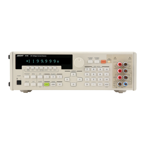
6166 DC Voltage Current Source Operation Manual 2.1.1 Display Section 2.1.1 Display Section The screen employs a dot matrix vacuum fluorescent display. Figure 2-2 Display Section Display Displays the source value, the limit values and the unit operational status. Also, functions as a setting screen for setting parameters. -
Page 37: Range Section
6166 DC Voltage Current Source Operation Manual 2.1.3 RANGE Section mA key Switches to current source (1 mA, 10 mA or 100 mA range) after numeric data input. ENTER key Finishes data entry and stores the parameter. LOCAL key Switches from remote operation to local operation. -
Page 38: Polarity Section
6166 DC Voltage Current Source Operation Manual 2.1.4 POLARITY Section 2.1.4 POLARITY Section The POLARITY section consists of keys to set the source value polarity and zero output. Figure 2-5 POLARITY Section - key Sets the polarity of the source value to negative. -
Page 39: Program Section
6166 DC Voltage Current Source Operation Manual 2.1.6 PROGRAM Section 2.1.6 PROGRAM Section The PROGRAM section consists of keys to set or perform the program function. Figure 2-7 PROGRAM Section PROGRAM key Sets the program function to ON or OFF. -
Page 40: Menu/Display Section
6166 DC Voltage Current Source Operation Manual 2.1.7 MENU/DISPLAY Section 2.1.7 MENU/DISPLAY Section The MENU/DISPLAY section consists of keys to set the parameter group and the display. Figure 2-8 MENU/DISPLAY Section MENU key Switches to the menu screen to set the parameter group. -
Page 41: Cursor Section
6166 DC Voltage Current Source Operation Manual 2.1.8 CURSOR Section 2.1.8 CURSOR Section Figure 2-9 CURSOR Section , keys Moves the cursor (highlight) that indicates a digit of the source value to the right or left. Selects items on the menu screen. -
Page 42: Output Section
6166 DC Voltage Current Source Operation Manual 2.1.9 OUTPUT Section 2.1.9 OUTPUT Section The OUTPUT section consists of keys to make output-related settings. Figure 2-10 OUTPUT Section EXTERNAL SENSE key Selects either output sensing 2-wire connection or 4-wire connec- tion. -
Page 43: 2.1.10 Digit Section
6166 DC Voltage Current Source Operation Manual 2.1.10 DIGIT Section 2.1.10 DIGIT Section The DIGIT section consists of keys to change the source value with the rotary knob. Figure 2-11 DIGIT Section to 10 -digit keys Enabled when the program function is set to OFF. Corresponds to the digits of the source value respectively. -
Page 44: Power Switch
6166 DC Voltage Current Source Operation Manual 2.1.12 POWER Switch GUARD terminal Guard terminal The voltages printed between the terminals are described in the table below: Table 2-1 Output Terminal Printing Description between Terminal 1 Terminal 1 Terminal 2 Printing... -
Page 45: Screen Display (Annotations)
6166 DC Voltage Current Source Operation Manual 2.2 Screen Display (Annotations) Screen Display (Annotations) This section describes the screen display (annotations). The screen is displayed in 1 line or 2 lines, which can be selected by the DISPLAY key on the front panel. - Page 46 RMT: Appears in remote control (except BCD remote con- trol). BCD: Appears in BCD remote control. Remote 2 Appears when the 6166 is addressed as Lister or Talker in remote control . Appears when the 6161-compatible operation is set to ON.
-
Page 47: Rear Panel
This section describes the connectors on the rear panel. Figure 2-15 Rear Panel AC power connector Used to connect the 6166 to the AC power supply by using the supplied power cable. Voltage selector and fuse holder Voltage can be switched manually to match the AC power supply. -
Page 48: Rear Output Terminal Block
BCD connector Used to remotely control the 6166 by BCD. (Mounted when the OPT6166+04 is specified.) GPIB connector Used to remotely control the 6166 by GPIB. -
Page 49: Basic Operation
6166 DC Voltage Current Source Operation Manual 3. BASIC OPERATION BASIC OPERATION This chapter describes how to operate the 6166 using examples. NOTE: The operation procedures listed permit the settings to be made in the shortest time. If the display differs from the one shown, repeat the procedure from the beginning. -
Page 50: Setting Source Value Using Numeric Keypad
This section describes the procedures of setting the source value using the numeric keypad and outputting it. Each procedure should be started with the initial state (factory default settings). If the 6166 is not in the initial state, initialize the 6166 referring to Section 3.11, "Initializing Setting Conditions" previously. -
Page 51: Outputting Current With Numeric Keypad
6166 DC Voltage Current Source Operation Manual 3.2.2 Outputting Current with Numeric Keypad Press to output the source value (Operate). While the source value is output, the OPERATE key lights up. Press again to stop the output (Standby). The OPERATE key goes OFF. -
Page 52: Outputting Divider Voltage With Numeric Keypad
6166 DC Voltage Current Source Operation Manual 3.2.3 Outputting Divider Voltage with Numeric Keypad Press to output the source value (Operate). While the source value is output, the OPERATE key lights up. • For current source, the voltage limit may be detected if the load is not connected. - Page 53 6166 DC Voltage Current Source Operation Manual 3.2.3 Outputting Divider Voltage with Numeric Keypad Press to set the source value to +100 mV. When the divider voltage function is set to ON, the DIVIDER key goes ON. • When the unit is previously set to "mV," entering can be omitted.
-
Page 54: Source Range
6166 DC Voltage Current Source Operation Manual 3.2.4 Source Range 3.2.4 Source Range The following table shows the relationship between the input values and the source ranges in setting the source value using the numeric keypad. Table 3-1 Source Ranges... -
Page 55: Setting Source Value Using Rotary Knob
6166 DC Voltage Current Source Operation Manual 3.3 Setting Source Value Using Rotary Knob Setting Source Value Using Rotary Knob 3.3.1 Outputting Voltage with Rotary Knob (Fixed Range) The following shows the procedure of outputting voltage of -11.5555 V. Operating procedure Press to select fixed range. - Page 56 6166 DC Voltage Current Source Operation Manual 3.3.1 Outputting Voltage with Rotary Knob (Fixed Range) Rotate the rotary knob to turn the figure to 5. Example display Similarly, press the DIGIT key corresponding to a digit to be changed, and rotate the rotary knob to set the source value.
-
Page 57: Outputting Current With Rotary Knob (Fixed Range)
6166 DC Voltage Current Source Operation Manual 3.3.2 Outputting Current with Rotary Knob (Fixed Range) When fixed range is selected, the source value can be set only within the source range of the currently selected range. Table 3-2 Voltage Source Ranges for Fixed Range... - Page 58 6166 DC Voltage Current Source Operation Manual 3.3.2 Outputting Current with Rotary Knob (Fixed Range) Press to select 100 mA range. Example display Press the rightmost DIGIT key to select a digit to be changed. The cursor (highlight) appears on the selected digit.
-
Page 59: Outputting Voltage With Rotary Knob (Auto Range)
6166 DC Voltage Current Source Operation Manual 3.3.3 Outputting Voltage with Rotary Knob (Auto Range) When the voltage limit is 55 V or higher, the output status becomes Standby after limit detection. When it is less than 55 V, press again to stop the output (Standby). - Page 60 6166 DC Voltage Current Source Operation Manual 3.3.3 Outputting Voltage with Rotary Knob (Auto Range) Press to set the voltage function to +11.999 V. • When the unit is previously set to "V," entering can be omitted. Example display Press the third DIGIT key from the right to select a digit to be changed.
-
Page 61: Source Ranges For Auto Range
6166 DC Voltage Current Source Operation Manual 3.3.3 Outputting Voltage with Rotary Knob (Auto Range) The following table shows the source ranges when auto range is selected. Table 3-4 Source Ranges for Auto Range Source function Range Source range 00.00000 to 11.99999 mV... -
Page 62: Setting Zero And Changing Polarity
6166 DC Voltage Current Source Operation Manual 3.4 Setting Zero and Changing Polarity Setting Zero and Changing Polarity This section describes the procedures of setting the source value to zero and setting its polarity. 3.4.1 Setting Zero This section describes the procedures of setting the source value to zero. - Page 63 6166 DC Voltage Current Source Operation Manual 3.4.1 Setting Zero To release zero value display (output), press on the POLARITY sec- tion. The original source value is displayed. However, pressing the reverse polarity of the original value switches the polarity.
-
Page 64: Setting Polarity
6166 DC Voltage Current Source Operation Manual 3.4.2 Setting Polarity 3.4.2 Setting Polarity This section describes the procedures of setting the polarity. There are the following two methods to set the polarity: (1) Using on the POLARITY section. (2) Using the numeric keypad. - Page 65 6166 DC Voltage Current Source Operation Manual 3.4.2 Setting Polarity (2) Example using the numeric keypad Operating procedure Check that the program function is set to OFF. When the program function is set to ON, the PROGRAM key lights up. Pressing the PROGRAM key sets it to OFF.
-
Page 66: Changing Source Function
6166 DC Voltage Current Source Operation Manual 3.5 Changing Source Function Changing Source Function The 6166 has the following four source functions: (1) Voltage function (Output from the OUTPUT terminals) (2) Current function (Output from the OUTPUT terminals) (3) Divider voltage function (Output from the DIVIDED OUTPUT terminals) (4) Thermal electromotive force function (Output from the DIVIDED OUTPUT terminals) This section describes the procedures of setting the above source functions. - Page 67 6166 DC Voltage Current Source Operation Manual 3.5 Changing Source Function The following is an example to select 10 V range of the voltage function and set the source value to +10 V. Press The 10 V range of the voltage function is selected and the source value is set to +10 V.
- Page 68 6166 DC Voltage Current Source Operation Manual 3.5 Changing Source Function The following is an example to select 10 mA range of the current function and set the source value to +10 mA. Press The 10 mA range of the current function is selected and the source value is set to +10 mA.
-
Page 69: Changing Range
6166 DC Voltage Current Source Operation Manual 3.6 Changing Range The following is an example to select 100 mV range of the divider voltage function and set the source value to +100 mV. Press The 100 mV range of the divider voltage function is selected and the source value is set to +100 mV. - Page 70 6166 DC Voltage Current Source Operation Manual 3.6 Changing Range Press to select the minimum range (1 V range) of the voltage function and set the source value to +1 V. Example display (1-line display) The following shows an example in 2-line display.
- Page 71 6166 DC Voltage Current Source Operation Manual 3.6 Changing Range Press again. The voltage range is raised from 100 V range to 1000 V range. The source value becomes +1 V of the 1000 V range. Currently set range (1000 V range)
-
Page 72: Setting Limit Values
Setting Limit Values Both voltage and current limit values can be set regardless of the voltage or current function on the 6166. Setting the maximum allowable voltage and current of the load as limit values in advance can prevent any trouble caused by incorrect setting of the source value. - Page 73 6166 DC Voltage Current Source Operation Manual 3.7.1 Setting Voltage and Current Limit Values User setting voltage and current limit values and internal setting voltage and current limit values and the currently set range are displayed. The user setting voltage and current limit values are set on the panel or by remote commands by the user.
-
Page 74: Voltage And Current Limit Detection
6166 DC Voltage Current Source Operation Manual 3.7.2 Voltage and Current Limit Detection 3.7.2 Voltage and Current Limit Detection When any limit is detected in Operate status, the LIMIT key goes ON in red and the screen is displayed as below. -
Page 75: Internal Setting Ranges Of Limit Values
1 mA to 125 mA 100 mA Current 1 mA 130 V 10 V to 1250 V 13 mA 1 mA to 13 mA (OPT6166+20) 10 mA NOTE: The internal setting limit values are stored when the 6166 is turned OFF. 3-27... - Page 76 6166 DC Voltage Current Source Operation Manual 3.8 Program Function Program Function The program function is to previously save source data to the program memory that consists of 1000 data sets and to recall them arbitrarily. The following parameters can be saved in each memory number of the program memory.
-
Page 77: Memory Scan Operations
6166 DC Voltage Current Source Operation Manual 3.8 Program Function Table 3-8 Memory Scan Operations Scan Description Operation Remarks Repeat Scans the Tp: Step time data repeat- Trc: Range Value of the last No. edly at step change process- time inter- ing time vals. -
Page 78: Program Function On And Off
6166 DC Voltage Current Source Operation Manual 3.8.1 Program Function ON and OFF 3.8.1 Program Function ON and OFF This section describes the procedure of enabling the program function. Operating procedure Check that the source value screen is displayed. If the menu screen, limit setting screen or numeric keypad input screen is displayed, press the EXIT key. -
Page 79: Setting Program Memory
6166 DC Voltage Current Source Operation Manual 3.8.2 Setting Program Memory When the program function is set to ON, the functions printed below the following keys are enabled. Pressing again disables the program function and switches to the source value screen. - Page 80 6166 DC Voltage Current Source Operation Manual 3.8.2 Setting Program Memory (1) Operating procedure of setting the voltage source value in the memory Check that the source value screen is displayed. If the menu screen, limit setting screen or numeric keypad input screen is displayed, press the EXIT key.
- Page 81 6166 DC Voltage Current Source Operation Manual 3.8.2 Setting Program Memory The following source value is set in memory number 0 Reference Memory Source Type of Range Source value Limit value junction number function thermocouple temperature Voltage 10 V +11.00000 V...
- Page 82 6166 DC Voltage Current Source Operation Manual 3.8.2 Setting Program Memory Next, the limit values are set. Press to switch to the limit setting screen. The LIMIT key goes ON. Example display Memory setting on the limit setting screen Press to move the cursor (highlight), and change the value to 50 V with the rotary knob.
- Page 83 6166 DC Voltage Current Source Operation Manual 3.8.2 Setting Program Memory Press to move the cursor (highlight), and change the value to 50 mA with the rotary knob. Example display Memory setting on the limit setting screen The limit values also can be set using the numeric keypad. For more information, refer to Section 3.7.1, "Setting Voltage and Current Limit Values."...
- Page 84 6166 DC Voltage Current Source Operation Manual 3.8.2 Setting Program Memory Rotate the rotary knob to change the memory number to 1. Example display Memory setting screen Press to move the cursor (highlight) onto the source value. Example display Memory setting screen The unit cannot be changed with the rotary knob.
- Page 85 6166 DC Voltage Current Source Operation Manual 3.8.2 Setting Program Memory (3) Operating procedure of setting the divider voltage source value in the memory The following source value is set in memory number 2. Reference Memory Type of Source function...
- Page 86 6166 DC Voltage Current Source Operation Manual 3.8.2 Setting Program Memory Press to change the range to 100 mV range. Example display Memory setting screen Blank (No limit value setting) Press to move the cursor (highlight) onto the source value.
- Page 87 6166 DC Voltage Current Source Operation Manual 3.8.2 Setting Program Memory Rotate the rotary knob to change the memory number to 3. Example display Memory setting screen Press to move the cursor (highlight) onto the source value. Example display Memory setting screen Select MENU>TEMP>TC OUT, press...
- Page 88 6166 DC Voltage Current Source Operation Manual 3.8.2 Setting Program Memory Select MENU>TEMP>JIS Standard, press to enter the Input/Run level and select C1602- 1981. C1602-1981 is enabled. Press to exit the menu screen. The memory setting screen is returned and the JIS standard display becomes J81.
-
Page 89: Saving Program Memory
3.8.3 Saving Program Memory The data input in the program memory is saved in the volatile memory (RAM). When the 6166 is turned OFF, the data is erased. To prevent it, the data needs to be saved to the non-volatile memory. - Page 90 6166 DC Voltage Current Source Operation Manual 3.8.3 Saving Program Memory Press to save the memory. Example display Memory saving screen (Saving done) When memory saving is complete, the program screen is automatically returned. Example display Program screen To terminate the program function and return to the source value screen, press...
-
Page 91: Recalling Program Memory
6166 DC Voltage Current Source Operation Manual 3.8.4 Recalling Program Memory 3.8.4 Recalling Program Memory Recall is a method to call the program memory by specifying an arbitrary memory number. The following is an example to recall and output the data set in Section 3.8.2, "Setting Program Memory."... - Page 92 6166 DC Voltage Current Source Operation Manual 3.8.4 Recalling Program Memory Press . The source value of memory number 0 is output. While the source value is output, the OPERATE key lights up. Rotate the rotary knob to change the memory number to 1.
-
Page 93: Setting Program Memory Scan Operations
6166 DC Voltage Current Source Operation Manual 3.8.5 Setting Program Memory Scan Operations Press . The memory recall screen is switched to the program screen. Memory recall oper- ations are complete. Example display Memory recall screen To terminate the program function and return to the source value screen, press 3.8.5... - Page 94 6166 DC Voltage Current Source Operation Manual 3.8.5 Setting Program Memory Scan Operations Operating procedure Check that the source value screen is displayed. If the menu screen, limit setting screen or numeric keypad input screen is displayed, press the EXIT key.
-
Page 95: Setting First And Last Numbers And Step Time
6166 DC Voltage Current Source Operation Manual 3.8.6 Setting First and Last Numbers and Step Time 3.8.6 Setting First and Last Numbers and Step Time This section describes the procedure of setting the first number, the last number and the step time for scan operations. - Page 96 6166 DC Voltage Current Source Operation Manual 3.8.6 Setting First and Last Numbers and Step Time Example display Program screen Press . The first/last number and step time screen is displayed. Example display First/last number and step time screen Currently set step time...
-
Page 97: Starting, Stopping And Pausing Memory Scan
6166 DC Voltage Current Source Operation Manual 3.8.7 Starting, Stopping and Pausing Memory Scan Press . The first/last number and step time screen is switched to the program screen. Example display Program screen To terminate the program function and return to the source value screen, press 3.8.7... - Page 98 6166 DC Voltage Current Source Operation Manual 3.8.7 Starting, Stopping and Pausing Memory Scan For information on how to set the data and parameters, refer to Section 3.8.2, "Setting Program Memory" and Section 3.8.6, "Setting First and Last Numbers and Step Time."...
- Page 99 6166 DC Voltage Current Source Operation Manual 3.8.7 Starting, Stopping and Pausing Memory Scan Press to start the scan. The source value of memory number 0 is output. Display example Program screen Shows that the scan is in progress. Press again.
- Page 100 6166 DC Voltage Current Source Operation Manual 3.8.7 Starting, Stopping and Pausing Memory Scan (2) This is an example to execute Single scan. Operating procedure Check that the source value screen is displayed. If the menu screen, limit setting screen or numeric keypad input screen is displayed, press the EXIT key.
- Page 101 6166 DC Voltage Current Source Operation Manual 3.8.7 Starting, Stopping and Pausing Memory Scan Press to start the scan. The source values are output from memory number 0 at intervals of one second. Display example Program screen When the memory number reaches the last number 5, it returns to the first number 0 and the Single scan terminates.
- Page 102 6166 DC Voltage Current Source Operation Manual 3.8.7 Starting, Stopping and Pausing Memory Scan (3) This is an example to execute Repeat scan. Operating procedure Check that the source value screen is displayed. If the menu screen, limit setting screen or numeric keypad input screen is displayed, press the EXIT key.
- Page 103 6166 DC Voltage Current Source Operation Manual 3.8.7 Starting, Stopping and Pausing Memory Scan Press to start the scan. The source values are output from memory number 0 at intervals of one second. Display example Program screen When the memory number reaches the last number 5, it returns to the first number 0 and the source values are output repeatedly from memory number 0 at intervals of one second.
-
Page 104: Menu Operation
6166 DC Voltage Current Source Operation Manual 3.9 Menu Operation Menu Operation The 6166 functions and parameters are set on a hierarchical menu. This section describes the menu structure and the procedures of operating the menu. 3.9.1 Menu Structure The menu is a 3-level hierarchical structure. -
Page 105: Menu Structure
6166 DC Voltage Current Source Operation Manual 3.9.1 Menu Structure Figure 3-1 Menu Structure 3-57... -
Page 106: Menu Operation Example (Parameter To Be Selected)
6166 DC Voltage Current Source Operation Manual 3.9.2 Menu Operation Example (Parameter to Be Selected) or the rotary knob to select the categories. to move from the Category level to the Select level. or the rotary knob to select the parameters at the Select level. - Page 107 6166 DC Voltage Current Source Operation Manual 3.9.2 Menu Operation Example (Parameter to Be Selected) Example display Category level Pressing moves the cursor (highlight) and selects the categories. The categories can be selected by using the rotary knob. Move the cursor to SYSTEM.
- Page 108 6166 DC Voltage Current Source Operation Manual 3.9.2 Menu Operation Example (Parameter to Be Selected) Press to move to the Input/Run level in the SYSTEM category. Example display Menu screen: Input/Run level Press to select ON. Example display Menu screen: Input/Run level Press to exit the menu screen.
-
Page 109: Menu Operation Example (Parameter To Be Input)
6166 DC Voltage Current Source Operation Manual 3.9.3 Menu Operation Example (Parameter to Be Input) 3.9.3 Menu Operation Example (Parameter to Be Input) This section describes the procedure of setting the reference junction temperature as an example of how to change the parameter values from the menu. - Page 110 6166 DC Voltage Current Source Operation Manual 3.9.3 Menu Operation Example (Parameter to Be Input) Example display Category level Press Pressing moves to the parameter select level in the TEMP category. There are the following parameters in the TEMP category.
- Page 111 6166 DC Voltage Current Source Operation Manual 3.9.3 Menu Operation Example (Parameter to Be Input) Rotate the rotary knob to change the figure. The figures cannot be changed with The setting range is from -270.0C to +120.0C. In this example, the temperature is set to -270.0C.
-
Page 112: Menu Operation Example (Parameter To Be Run)
6166 DC Voltage Current Source Operation Manual 3.9.4 Menu Operation Example (Parameter to Be Run) 3.9.4 Menu Operation Example (Parameter to Be Run) This section describes the procedure of initializing the program memory as an example of how to execute the parameters from the menu. - Page 113 6166 DC Voltage Current Source Operation Manual 3.9.4 Menu Operation Example (Parameter to Be Run) Pressing moves the cursor (highlight) and selects the categories. The categories can be selected by using the rotary knob. Move the cursor to MEMORY. To move to MEMORY, press once or six times.
- Page 114 6166 DC Voltage Current Source Operation Manual 3.9.4 Menu Operation Example (Parameter to Be Run) Press to clear the program memory. Shows that the parameter execution is complete. Example display Menu screen: Input/Run level Moves to the Select level automatically after execution.
-
Page 115: Setting Thermal Electromotive Force Function
6166 DC Voltage Current Source Operation Manual 3.10 Thermal Electromotive Force Function 3.10 Thermal Electromotive Force Function The thermal electromotive force function generates voltages equivalent to the thermal electromotive forces of eight types of thermocouples by specifying the temperature values. The thermal electromotive forces are output from the DIVIDED OUT terminals. - Page 116 6166 DC Voltage Current Source Operation Manual 3.10.1 Setting Thermal Electromotive Force Function Operating procedure Press . The menu screen appears. The MENU key lights up during menu screen display. Example display Press to select TEMP. Example display Press to move the Select level.
- Page 117 6166 DC Voltage Current Source Operation Manual 3.10.1 Setting Thermal Electromotive Force Function Pressing switches the screen to 2-line display. In the following example display, a voltage equivalent to the thermal electromotive force against the set temperature and the temperature of the reference junction are displayed.
-
Page 118: Setting Type Of Thermocouple
6166 DC Voltage Current Source Operation Manual 3.10.2 Setting Type of Thermocouple For information on how to set the temperature using the rotary knob, refer to Section 3.3, "Setting Source Value Using Rotary Knob." NOTE: • The temperature setting range varies depending on the type of thermocouple. For more information, refer to Table 3-12, "Types of Thermocouples and Setting Temperature Ranges."... - Page 119 6166 DC Voltage Current Source Operation Manual 3.10.2 Setting Type of Thermocouple The following shows the procedure of selecting type B thermocouple and then JIS C1602-1981. Operating procedure Set the thermal electromotive force function previously. For information on how to set it, refer to Section 3.10.1, "Setting Thermal Electromotive Force Function."...
- Page 120 6166 DC Voltage Current Source Operation Manual 3.10.2 Setting Type of Thermocouple Press to move to the Input/Run level. Example display Press to select Type B. The highlight section switches as Type T Type J Type E Type K Type S Type R ...
-
Page 121: Setting Reference Junction Temperature
6166 DC Voltage Current Source Operation Manual 3.10.3 Setting Reference Junction Temperature Press to exit the menu screen. Shows that the type of thermocouple is set to B. The temperature for generating the thermal electromotive force can be set on the source value screen by using the numeric keypad or rotary knob as the voltage source value or current source value. -
Page 122: 3.11 Initializing Setting Conditions
6166 DC Voltage Current Source Operation Manual 3.11 Initializing Setting Conditions 3.11 Initializing Setting Conditions This section describes the procedure of initializing the setting conditions (parameters) of the 6166. There are the following two types of initialization by key operations: •... - Page 123 6166 DC Voltage Current Source Operation Manual 3.11.1 Initializing Parameters from Menu Example display Press to select Initialize. The highlight section switches as Power ON Load Param Save Param Load Initialize. Example display Press to move to the Input/Run level.
-
Page 124: Restoring To Factory Default Settings
Turn off the power. Turn on the power while pressing at the same time. Example display Indicates that the 6166 is booting up. The 6166 starts up with all the parameters restored to the factory default settings. Example display 3-76... -
Page 125: Setting Parameter Initial Values
6166 DC Voltage Current Source Operation Manual 3.11.2 Restoring to Factory Default Settings Table 3-13 Setting Parameter Initial Values (1 of 3) 6166 compatible 6166 USER parameter Source memory MENU Initial Power Initial Factory Power Parameter initializ *RST *CLS *RCLx *SAVx... - Page 126 6166 DC Voltage Current Source Operation Manual 3.11.2 Restoring to Factory Default Settings Table 3-13 Setting Parameter Initial Values (2 of 3) 6166 compatible 6166 USER parameter Source memory MENU Initial Power Initial Factory Power Parameter initializ *RST *CLS *RCLx *SAVx...
- Page 127 6166 DC Voltage Current Source Operation Manual 3.11.2 Restoring to Factory Default Settings Table 3-13 Setting Parameter Initial Values (3 of 3) 6166 compatible 6166 USER parameter Source memory MENU Initial Power Initial Factory Power Parameter initializ *RST *CLS *RCLx *SAVx...
-
Page 128: 3.12 Saving And Loading Parameters
Auto Parameter Loading at Power ON The 6166 memorizes the settings at power OFF and starts up with the same settings at next power ON. To start up using predefined parameters, parameters saved in USER0 can be loaded at startup. - Page 129 6166 DC Voltage Current Source Operation Manual 3.12.1 Auto Parameter Loading at Power ON Press to select PARAM. Example display Press to move the Select level. Example display Press to move to the Input/Run level. Example display Press to select USER0.
-
Page 130: Saving Parameters
The 6166 can start up with the parameters saved in USER0 at power ON. For information on how to load the parameters, refer to Section 3.12.3, "Loading Parameters." For information on how to start the 6166 with the parameters saved in USER0, refer to Section 3.12.1, "Auto Parameter Loading at Power ON."... - Page 131 6166 DC Voltage Current Source Operation Manual 3.12.2 Saving Parameters Press to move the Select level. Example display Press to select Param Save. The highlight section switches as Power ON Load Param Save Param Load Initialize. Example display Press to move to the Input/Run level.
-
Page 132: Loading Parameters
6166 DC Voltage Current Source Operation Manual 3.12.3 Loading Parameters The descriptions of these parameters are as follows: USER0 Saves the parameters to USER0. USER1 Saves the parameters to USER1. USER2 Saves the parameters to USER2. USER3 Saves the parameters to USER3. - Page 133 6166 DC Voltage Current Source Operation Manual 3.12.3 Loading Parameters Press to select PARAM. Example display Press to move the Select level. Example display Press to select Param Load. The highlight section switches as Power ON Load Param Save Param Load Initialize.
- Page 134 6166 DC Voltage Current Source Operation Manual 3.12.3 Loading Parameters Press to load the parameters. Example display Indicates that parameter loading is complete. Example display Moves automatically to the upper level. The descriptions of these parameters are as follows: USER0 Loads the parameters from USER0.
-
Page 135: Menu Index
6166 DC Voltage Current Source Operation Manual 4. FUNCTION REFERENCE FUNCTION REFERENCE This chapter describes panel keys, parameter groups, parameter items and parameter functions in the follow- ing sections: • 4.1 Menu Index: Use this section as an index for the parameters in the menu. -
Page 136: Panel Key Descriptions
6166 DC Voltage Current Source Operation Manual 4.2 Panel Key Descriptions Panel Key Descriptions This section describes the function of the panel keys and the parameters in the menu in alphabetical order. 4.2.1 AUTO Key (Source Range) Turns ON or OFF auto range that selects the optimal range automatically. -
Page 137: Display Key
6166 DC Voltage Current Source Operation Manual 4.2.4 DISPLAY Key 4.2.4 DISPLAY Key Switches the display section (vacuum fluorescent display) between 1-line display and 2-line display. NOTE: When the screen is turns OFF from the MENU, the DISPLAY key blinks. Pressing the DISPLAY key in this state will cancel the screen OFF setting and the DISPLAY key goes OFF. -
Page 138: Fno./Lno. Step Time Key (First/Last Number And Step Time Setting)
6166 DC Voltage Current Source Operation Manual 4.2.10 FNo./LNo. STEP TIME Key (First/Last Number and Step Time Setting) 4.2.10 FNo./LNo. STEP TIME Key (First/Last Number and Step Time Setting) Sets the first number, last number and step time for scan operation when the program function is set to ON. - Page 139 6166 DC Voltage Current Source Operation Manual 4.2.13 MENU Key (Parameter Setting) Polar Type Selects either bipolar or unipolar operation. Bipolar: The polarity switches across zero in changing the source value with the rotary knob. Unipolar: The polarity does not change, stopping at zero in changing the source value with the rotary knob.
- Page 140 6166 DC Voltage Current Source Operation Manual 4.2.13 MENU Key (Parameter Setting) PARAM Loads or saves the setting parameters. Power ON Load Selects the setting parameter condition at power ON. Power OFF: Start up using the parameters saved when the power was last turned off.
- Page 141 6166 DC Voltage Current Source Operation Manual 4.2.13 MENU Key (Parameter Setting) 6161 Compati Sets the 6161-compatible operation to ON or OFF. OFF: Normal operation 6161-compatible operation For more information, refer to Section 6.1.2, "Compatibility with Former Model" and Section 6.6.3, "Remote Command Index."...
-
Page 142: Operate Key (Output On/Off)
6166 DC Voltage Current Source Operation Manual 4.2.14 OPERATE Key (Output ON/OFF) LED Bright Adjusts the key indicator (LED) brightness in three levels. 1/3 Low: 1/3 brightness, lowest level 2/3 Def: 2/3 brightness, default level 3/3: 3/3 brightness, highest level Error Log The data stored in the error log can be read when ERR is displayed. -
Page 143: Program Key (Switching To And Releasing Program Function)
6166 DC Voltage Current Source Operation Manual 4.2.18 PROGRAM Key (Switching to and Releasing Program Function) 4.2.18 PROGRAM Key (Switching to and Releasing Program Function) Sets the program function to ON or OFF. The PROGRAM key lights up when the program function is set to ON. -
Page 144: Scan Key (Setting Memory Scan)
6166 DC Voltage Current Source Operation Manual 4.2.22 SCAN Key (Setting Memory Scan) 4.2.22 SCAN Key (Setting Memory Scan) Selects the memory scan operations when the program function is set to ON. There are the following three types of scan operations. -
Page 145: Operational Descriptions
Configuration of Output Terminals The 6166 has four output terminals, two of which are positive terminals (red) and the other two are nega- tive terminals (black). Both type of the terminals are divided into an OUTPUT terminal and a SENSE ter- minal. - Page 146 6166 DC Voltage Current Source Operation Manual 5.1.2 2-Wire and 4-Wire Connections r1, r2: Lead resistance Terminal voltage of RL Load Error Figure 5-1 2-Wire Connection r1, r2, r3, r4:Lead resistance Terminal voltage of RL Load Load current Error Figure 5-2 4-Wire Connection...
-
Page 147: Error Due To Cable Resistance In 4-Wire Connection
6166 DC Voltage Current Source Operation Manual 5.1.2 2-Wire and 4-Wire Connections Table 5-1 Error Due to Cable Resistance in 4-Wire Connection Range r1/r4 Error 250 m Approx. 0.001 % 1 10 V Approx. 0.001 % 10 100 V Approx. -
Page 148: How To Use Guard Terminal
GUARD terminal of the 6166 and the other side is connected to the low impedance side from the ground of the load together with the output end. -
Page 149: How To Use Guard Terminal (4-Wire Connection)
6166 DC Voltage Current Source Operation Manual 5.1.3 How to Use Guard Terminal Load (Red) (Red) (Black) (Black) Shielded cable (Blue) *1 This relay opens when EXTERNAL GUARD lights up. Chassis Case Figure 5-4 How to Use Guard Terminal (4-Wire Connection) -
Page 150: Selecting Standby Status
5.1.4 Selecting Standby Status The 6166 can change the standby status by using the discharge switch (S1). To set the discharge switch to ON, operate as MENU > SOURCE > DischargeSW > OFF ON. "D" is displayed when the 2-line displayed is selected. Refer to Section 2.2, "Screen Display (Annota- tions)."... -
Page 151: Source And Sink Operations
5.2 Source and Sink Operations Source and Sink Operations As the output from the 6166 is bipolar, current source operation and partially current sink operation are available. The sink operation must be within the following operating zones. Otherwise, the internal circuits may be damaged. -
Page 152: High Voltage Indicator Operation And Output Status
6166 DC Voltage Current Source Operation Manual 5.3 HIGH VOLTAGE Indicator Operation and Output Status HIGH VOLTAGE Indicator Operation and Output Status 5.3.1 HIGH VOLTAGE Indicator Operation The HIGH VOLTAGE indicator on the front panel turns ON for safety when the voltage source value or voltage limit value is set to 55 V or more. -
Page 153: Output Operation Timing
6166 DC Voltage Current Source Operation Manual 5.4 Output Operation Timing Output Operation Timing Table 5-4 Output Operation Timing List Range Topr Tstby Trng Settling time (*2) 10 mV 100 ms 25 ms 20 ms 20 ms 1 s or less... -
Page 154: Output On (Opr)/Off (Stby) Timing
6166 DC Voltage Current Source Operation Manual 5.4.2 Output ON (OPR)/OFF (STBY) Timing 5.4.2 Output ON (OPR)/OFF (STBY) Timing Settling time OPR command OPR key operation 5.4.3 Range Change Timing Range after change Range before change Settling time Range change command... -
Page 155: Function Change Timing
6166 DC Voltage Current Source Operation Manual 5.4.4 Function Change Timing 5.4.4 Function Change Timing Function after change Function before change Settling time Function command key operation Tfun VS IS 45 ms VS DIV 45 ms IS VS 65 ms IS ... -
Page 156: Polarity Change Timing
6166 DC Voltage Current Source Operation Manual 5.4.5 Polarity Change Timing 5.4.5 Polarity Change Timing The polarity change timing is the same as the setting data change timing in Section 5.4.1. However, the polarity change timing in the 1000 V range, and the 1 mA and 10 mA of OPT6166+20 is as follows: Approx. -
Page 157: Other Operations
6166 DC Voltage Current Source Operation Manual 5.5 Other Operations Other Operations 5.5.1 Precautions for Setting Voltage Limit In scan operation or remote operation, the limiter may be activated during output response to source value change under the following conditions: •... -
Page 158: Voltage Limit Error At Current Source
6166 DC Voltage Current Source Operation Manual 5.5.2 Voltage Limit Error at Current Source 5.5.2 Voltage Limit Error at Current Source The voltage limit detection method for current source adopted by the 6166 increases errors at lower limit values. Load Voltage... -
Page 159: Voltage Output (1000 V And 100 V Ranges) And Current Limit Detection
6166 DC Voltage Current Source Operation Manual 5.5.3 Voltage Output (1000 V and 100 V Ranges) and Current Limit Detection 5.5.3 Voltage Output (1000 V and 100 V Ranges) and Current Limit Detection When voltage is output in the 1000 V range with the current limit set to the lowest level, the current limiter is activated by the charge current of the capacitor of approx. -
Page 160: Trigger In Signal
6166 DC Voltage Current Source Operation Manual 5.5.4 TRIGGER IN Signal 5.5.4 TRIGGER IN Signal The TRIGGER IN signal triggers the 6166 from the external device. The following table shows the modes and their operations. Table 5-5 TRIGGER IN Signal Operations Program function ON/OFF... -
Page 161: Trigger In Input Circuit
Ensure that the TRIGGER IN signal and the trigger from the keys or remote commands do not over- lap. Allow the 6166 at least 10 ms after completion of the previous scan to input the TRIGGER IN signal for scan start. -
Page 162: Interlock Input Signal
6166 DC Voltage Current Source Operation Manual 5.5.5 INTERLOCK Input Signal 5.5.5 INTERLOCK Input Signal The INTERLOCK signal is used to prevent unexpected outputs by connecting to the external device such as fixture. The INTERLOCK signal can be set to ON or OFF from the menu. For more information, refer to Section 3.9, "Menu Operation."... -
Page 163: 5.5.6 Self Test
5.5.6 Self Test 5.5.6 Self Test The 6166 can self-test internal operations by turning on the power, executing the remote command, or manual operation. For more information on the self-test items and output results, see Table 5-6. (1) Self-test execution by key operation or turning the power ON When the power is turned ON, the self test is executed automatically. - Page 164 6166 DC Voltage Current Source Operation Manual 5.5.6 Self Test Table 5-6 Self-Test Items Executing method Display error Description code Power ON *TST? Key operation VL DAC output check (Full) error VL DAC output check (1/2 Full) error IL DAC output check (Full) error...
-
Page 165: Error Log
5.5.7 Error Log 5.5.7 Error Log The 6166 holds the error number in the error log memory when it detects an error. Operation A maximum of twenty memory areas are available for the error log and they operate as follows: •... -
Page 166: Operational Principles
5.6 Operational Principles Operational Principles The 6166 amplifier configurations for constant voltage output and constant current output are shown in the following figures. Figure 5-10 shows the circuit configuration for constant voltage output, and the output voltage is obtained as follows: Switching Rf sets the range and setting Eref specifies the output level. -
Page 167: Circuit Configuration For Constant Voltage
6166 DC Voltage Current Source Operation Manual 5.6 Operational Principles Figure 5-10 Circuit Configuration for Constant Voltage Load Figure 5-11 Circuit Configuration for Constant Current Figure 5-12 Circuit Configuration for Divider Voltage and Thermal Electromotive Force Output 5-23... -
Page 169: Remote Programming
6. REMOTE PROGRAMMING REMOTE PROGRAMMING Using Interface The 6166 offers GPIB and USB interfaces. In addition, a BCD interface is available as OPT6166+04. They cannot be used at the same time. Select which interface you wish to use. 6.1.1 Selecting Interface The interface is selected from the front panel menu. - Page 170 6166 DC Voltage Current Source Operation Manual 6.1.1 Selecting Interface Operating procedure Press . The menu screen appears. The MENU key lights up during menu screen display. Example display Press to select I/F. Example display Press to move the Select level.
-
Page 171: Compatibility With Former Model
6.1.2 Compatibility with Former Model The 6166 can operate with the remote commands for the former model 6166 when the 6161-compatible operation is set to ON. The following shows the functional differences when the 6161-compatible operation is set to ON: •... - Page 172 6166 DC Voltage Current Source Operation Manual 6.1.2 Compatibility with Former Model Operating procedure Press . The menu screen appears. The MENU key lights up during menu screen display. Example display Press to select I/F. Example display Press to move the Select level.
-
Page 173: Status Register Structure
Status Register Structure The 6166 has a hierarchical status register structure that conforms to the IEEE standard 488.2-1987 and can send various statuses of the 6166 to the controller. The following explains an operational model of the status structure and assigning events. -
Page 174: Status Byte Register Structure
Event Register, and the OR result is generated as a summary. The summary is written into the Status Byte Register. Data can be written into the Enable Register in decimal values. The 6166 has the following three types of status registers. • Status Byte Register (STB) • Standard Event Status Register (SESR) •... - Page 175 6166 DC Voltage Current Source Operation Manual 6.2.1 Status Register The Status Byte Register conforms to the Status Register except for the following three points. • The summary of the Status Byte Register is written into bit 6 of the Status Byte Register.
-
Page 176: Status Register Structure
6166 DC Voltage Current Source Operation Manual 6.2.1 Status Register Device Event Status Register The functions assigned to the Device Event Status Register are described in Table 6-3. Device Event Status Register Over Load Fan Stop Over Heat Source Unit Error... -
Page 177: Status Byte Register (Stb)
6166 DC Voltage Current Source Operation Manual 6.2.1 Status Register Table 6-1 Status Byte Register (STB) Name Description Not in use Always set to 0 Not in use Always set to 0 ON: Set to 1 when error information is stored in Error Queue. -
Page 178: Standard Event Status Register (Esr)
6166 DC Voltage Current Source Operation Manual 6.2.1 Status Register Table 6-2 Standard Event Status Register (ESR) Name Description ON: Set to 1 when all operation is completed after receiving the *OPC Operation Complete command. Not in use Always set to 0... - Page 179 6166 DC Voltage Current Source Operation Manual 6.2.1 Status Register Table 6-3 Device Event Status Register (DSR) (2 of 2) Name Description ON: Set to 1 when the negative current limiter is detected. Minus I Limiter ON: Set to 1 when Operate is set to OFF by the interlock signal.
-
Page 180: Status Register In 6166-Compatible Operation
6166 DC Voltage Current Source Operation Manual 6.2.2 Status Register in 6166-Compatible Operation 6.2.2 Status Register in 6166-Compatible Operation Figure 6-3 below shows the structure of the Status Byte Register in the 6166-compatible operation, and Table 6-4 describes each bit. Status Byte Register Limit... -
Page 181: Status Byte Register (Stb) In 6161-Compatible Operation
6166 DC Voltage Current Source Operation Manual 6.2.2 Status Register in 6166-Compatible Operation Table 6-4 Status Byte Register (STB) in 6161-Compatible Operation Name Description LIMIT ON: Set to 1 when +/- VL or +/- IL limiter is detected. OFF: Set to 1 when the limiter is released. -
Page 182: Gpib
As GPIB signals from the 6166 are electrically isolated inside the unit from the source signal system, the connection of external devices does not affect the source values. -
Page 183: Precautions When Using Gpib
6166 DC Voltage Current Source Operation Manual 6.3.2 Precautions when Using GPIB 6.3.2 Precautions when Using GPIB Do not use too long a connection cable or bus cable to connect any instrument or controller. Ensure that the total cable length does not exceed 20 m. ADC CORPORATION offers the following standard bus cables. -
Page 184: Setting Gpib
6166 DC Voltage Current Source Operation Manual 6.3.3 Setting GPIB 6.3.3 Setting GPIB There are three setting items for GPIB: GPIB address, header and Listen only. This section describes how to set them. Referring to Section 6.1.1, "Selecting Interface," select the GPIB interface in advance. - Page 185 6166 DC Voltage Current Source Operation Manual 6.3.3 Setting GPIB Set the GPIB address by rotating the rotary knob. Example display Press to exit the menu screen. (2) Setting the header The header setting is available only in the 6161-compatible operation.
- Page 186 6166 DC Voltage Current Source Operation Manual 6.3.3 Setting GPIB Press to move to the Input/Run level. Example display Set the header to ON or OFF by rotating the rotary knob. Example display Press to exit the menu screen. (3) Setting Listen only The Listen only setting is available only in the 6161-compatible operation.
- Page 187 6166 DC Voltage Current Source Operation Manual 6.3.3 Setting GPIB Press to select the parameter. The highlight section switches as Bus Address Header Listen Only 6161 Compati. Example display Press to move to the Input/Run level.
-
Page 188: Usb
6.4.2 Connecting with Host Computer Connect the USB connector (B type) on the rear of the 6166 to the PC USB connector with a cable. Fully insert all the connectors. Use a USB hub to connect multiple instruments to a single PC. -
Page 189: Precautions When Using Usb
6166 DC Voltage Current Source Operation Manual 6.4.3 Precautions when Using USB 6.4.3 Precautions when Using USB When running a query command, leave a 20 ms wait time right after the previous command. USB is NOT available in the 6161-compatible operation. -
Page 190: Bcd Interface (Opt6166+04)
BCD Interface (OPT6166+04) 6.5.1 BCD Interface Overview The BCD parallel interface can be installed optionally on the 6166. The following five functions can be controlled in parallel via the 50-pin connector on the rear panel. Setting the output value (10 to 10 (2) Switching the function between voltage, current and divider voltage (10 mV, 100 mV, 1000 mV). -
Page 191: Selecting Bcd Interface
For information how to select the BCD interface, refer to Section 6.1.1, "Selecting Interface." When the BCD interface is selected, "BCD" appears on the upper right of the display section and the 6166 is set to remote control, disabling key operations. -
Page 192: Bcd Interface Signals
6166 DC Voltage Current Source Operation Manual 6.5.3 BCD Interface Signals 6.5.3 BCD Interface Signals The following tables shows the signal list of the BCD interface connector. Table 6-7 BCD Interface Signals Pin number Input/output Signal name Pin number Input/output... - Page 193 6166 DC Voltage Current Source Operation Manual 6.5.3 BCD Interface Signals NC: Not connected Used connector 57-40500 Amphenol (Unit side) 57-30500 Amphenol (Cable side) (1) Function and range setting Range setting V/I MODE (34) RANGE_1 (36) RANGE_0 (35) DIVIDER (38)
-
Page 194: 6.5.3 Bcd Interface Signals
6166 DC Voltage Current Source Operation Manual 6.5.3 BCD Interface Signals (3) Voltage/current limit setting Voltage limit VL_1 (42) VL_0 (41) 10 V 130 V 300 V 1250 V Voltage limit IL_1 (44) IL_0 (43) 5 mA 13 mA 50 mA... -
Page 195: Bcd Interface Electrical Signal Specifications
6166 DC Voltage Current Source Operation Manual 6.5.4 BCD Interface Electrical Signal Specifications 6.5.4 BCD Interface Electrical Signal Specifications All the electrical specifications are TTL negative logic (LO level: logic "1," HI level: logic "0"). Input equivalent circuit 74HC373 or equivalent... -
Page 196: Remote Commands
(,). For more information on the data types, refer to Section 6.6.2, "Data Format." Describing Multiple Commands The 6166 allows multiple commands to be described consecutively or separated by semicolon (;), com- ma (,), or space ( ) in one line. 6-28... -
Page 197: Data Format
6.6.2 Data Format 6.6.2 Data Format The 6166 uses the following data types for data input and output. Numeric data There are three numeric data formats, any of which can be used for input. Some commands can add units to the data when the data is input. -
Page 198: 6.6.3 Remote Command Index
6166 DC Voltage Current Source Operation Manual 6.6.3 Remote Command Index 6.6.3 Remote Command Index Use the following remote command index for using remote commands in Chapter 6. Remote Command Pages Remote Command Pages *CLS ............6-39, 6-48 DSE? ............6-39 *ESE ............ - Page 199 6166 DC Voltage Current Source Operation Manual 6.6.3 Remote Command Index PAU ............6-47 SVRX............6-33 PLM ............6-36 SWSP ............6-38 PLM? ............6-36 TC ............6-34 RCL............6-47 TC?............6-34 RCLM ............6-38 TF............. 6-32 RCLM? ............ 6-38 TF? ............
-
Page 200: Remote Command List
6166 DC Voltage Current Source Operation Manual 6.6.4 Remote Command List 6.6.4 Remote Command List 1. The Default column shows default settings at Power ON or at factory shipment. • The Power ON column shows the status when the power is turned ON. - Page 201 6166 DC Voltage Current Source Operation Manual 6.6.4 Remote Command List Default Operation Thermal Class Item Command Description electrom Power Factory Divider Scan Scan otive shipment function stopped running force function Source Voltage range SVRX Optimal range SVR4 SVR5 10 V...
- Page 202 6166 DC Voltage Current Source Operation Manual 6.6.4 Remote Command List Default Operation Thermal Class Item Command Description electrom Power Factory Divider Scan Scan otive shipment function stopped running force function Source Thermocouple Thermocouple type T, thermal electro- type motive force output (CC)
- Page 203 6166 DC Voltage Current Source Operation Manual 6.6.4 Remote Command List Default Operation Thermal Class Item Command Description electrom Power Factory Divider Scan Scan otive shipment function stopped running force function Source Divider volt- SODdata Divider voltage source value setting *1...
- Page 204 6166 DC Voltage Current Source Operation Manual 6.6.4 Remote Command List Default Operation Thermal Class Item Command Description electrom Power Factory Divider Scan Scan otive shipment function stopped running force function Source Limit value LMV data Voltage limit value setting 130 V LMVd.dddE+d...
-
Page 205: Source Ranges
6166 DC Voltage Current Source Operation Manual 6.6.4 Remote Command List Default Operation Thermal Class Item Command Description electrom Power Factory Divider Scan Scan otive shipment function stopped running force function Mem- Memory setting Nnnn Voltage/current Nnnn, nnn: memory number 0 to 999... - Page 206 6166 DC Voltage Current Source Operation Manual 6.6.4 Remote Command List Default Operation Thermal Class Item Command Description electrom Power Factory Divider Scan Scan otive shipment function stopped running force function Mem- Memory setting RSAV Saves memory data. RLOD Loads memory data.
- Page 207 6166 DC Voltage Current Source Operation Manual 6.6.4 Remote Command List Default Operation Thermal Class Item Command Description electrom Power Factory Divider Scan Scan otive shipment function stopped running force function Remote Block delim- CR/LF +EOI iter LF +EOI Query of block delimiter...
- Page 208 6166 DC Voltage Current Source Operation Manual 6.6.4 Remote Command List Default Operation Thermal Class Item Command Description electrom Power Factory Divider Scan Scan otive shipment function stopped running force function Remot Operation *OPC After all operations are complete, sets complete LSB of Standard Event Status Register.
- Page 209 6166 DC Voltage Current Source Operation Manual 6.6.4 Remote Command List Default Operation Thermal Class Item Command Description electrom Power Factory Divider Scan Scan otive shipment function stopped running force function System Limiter detec- Limit detection buzzer OFF tion buzzer...
- Page 210 6166 DC Voltage Current Source Operation Manual 6.6.4 Remote Command List Default Operation Thermal Class Item Command Description electrom Power Factory Divider Scan Scan otive shipment function stopped running force function System Parameter load *RCL0 Loads data from the non-volatile mem- ory, USER0 as setting parameters.
- Page 211 6166 DC Voltage Current Source Operation Manual 6.6.4 Remote Command List Default Operation Thermal Class Item Command Description Factory electrom Power Divider Scan Scan shipme otive function stopped running force function Cali- Calibration Calibration range setting bra- range Voltage range...
-
Page 212: 6161-Compatible Remote Command List
6166 DC Voltage Current Source Operation Manual 6.6.5 6161-Compatible Remote Command List 6.6.5 6161-Compatible Remote Command List (1) The following table shows commands compatible with the former model 6161. These commands are available only when the 6161-compatible mode is set to ON, except that the com- mands denoted by *5 are available when the 6161-compatible mode is set to OFF. - Page 213 6166 DC Voltage Current Source Operation Manual 6.6.5 6161-Compatible Remote Command List Default Operation Class Item Command Description Power Factory Divider Scan Scan shipment function stopped running Source Voltage limit VL data Voltage limit value setting (1 V step) 130 V...
- Page 214 6166 DC Voltage Current Source Operation Manual 6.6.5 6161-Compatible Remote Command List Default Operation Class Item Command Description Power Factory Divider Scan Scan shipment function stopped running Source Query of panel PANE? Setting parameter data reading setting Response: Setting range Vn, In Setting source value D+d.ddddduu uu: unit (Header ON)
- Page 215 6166 DC Voltage Current Source Operation Manual 6.6.5 6161-Compatible Remote Command List Default Operation Class Item Command Description Power Factory Divider Scan Scan shipment function stopped running Scan First number First number and last number setting Last number SCmm,nn 0, 99...
- Page 216 6166 DC Voltage Current Source Operation Manual 6.6.5 6161-Compatible Remote Command List Default Operation Class Item Command Description Power Factory Divider Scan Scan shipment function stopped running Remot Service request SRQ? Query of SRQ transmission Response: SRQOF: SRQ transmission is not allowed.
- Page 217 6166 DC Voltage Current Source Operation Manual 6.6.5 6161-Compatible Remote Command List Default Operation Class Item Command Description Power Factory Divider Scan Scan shipment function stopped running System Screen OFF Screen ON Screen OFF Screen OFF only in remote control...
-
Page 218: Sample Program
The 6166 generates DC voltage, and the digital multimeter measures voltage on or current through the load resistance. Example 2 The 6166 generates DC voltage set in the program memory in order using the memory scan func- tion, and the digital multimeter measures voltage on or current through the load resistance. •... -
Page 219: Performance Test
7. PERFORMANCE TEST PERFORMANCE TEST This chapter describes the methods for checking whether the 6166 operates in the specified accuracy. Measuring Instruments Necessary for Performance Test Use measuring instruments for the performance test which meet the specifications shown in Section 8.1, "Preparation for Calibration."... - Page 220 -FULL voltage limit -50 V • Current source/limiter test Connect the 6166 and a DMM as shown in Figure 8-1 (b). Set the DMM to DCV, auto range and integration time of 10 PLC or longer. Select current source. With ZERO and Full Scale generated in the 1 mA range to 100 mA range, ver- ify that the difference between the source value and the DMM measured value is within the accuracy described in Chapter 9, "SPECIFICATIONS."...
-
Page 221: Voltage/Current Source/Limiter Check Points
6166 DC Voltage Current Source Operation Manual 7.3 Test Method Table 7-1 Voltage/Current Source/Limiter Check Points Voltage source Range Check point VL setting IL setting +00.00000 mV 10 mV +10.00000 mV -10.00000 mV +000.0000 mV 100 mV +100.0000 mV -100.0000 mV +0000.000 mV... - Page 222 6166 DC Voltage Current Source Operation Manual 7.3 Test Method Table 7-1 Voltage/Current Source/Limiter Check Points Current source Standard Range Check point VL setting IL setting resistance +0.00000 mA 1 mA +1.00000 mA 1 k -1.00000 mA +00.0000 mA 100 ...
-
Page 223: Calibration
This chapter describes how to calibrate the 6166 to perform within the specified accuracy ranges. In order to use the 6166 in the specified accuracies, periodic calibration at least once a year is recommended. (To secure the 90-day or 180-days accuracy, execute calibration once every 90 days or 180 days.) Contact an ADC CORPORATION sales representative for the calibration service. -
Page 224: Connections
6166 DC Voltage Current Source Operation Manual 8.1.3 Connections 8.1.3 Connections The following figure shows connections for calibrating voltage source, voltage limiter and connection coefficient* using a DMM and connections for calibrating current source and current limiter using a DMM and a standard resistance. -
Page 225: Calibration Method
6166 DC Voltage Current Source Operation Manual 8.2 Calibration Method Calibration Method The 6166 can be calibrated manually or using the GPIB or USB remote commands. 8.2.1 Calibration Points and Tolerance Ranges For calibration, use the measurement instruments satisfying the required accuracy described in Section 8.1.1, "Measuring Instruments Necessary for Calibration", meeting the tolerance ranges shown in the fol-... -
Page 226: Outlined Calibration Procedure
6166 DC Voltage Current Source Operation Manual 8.2.2 Outlined Calibration Procedure 8.2.2 Outlined Calibration Procedure The calibration procedure is outlined below. Figure 8-2 Outlined Calibration Procedure... - Page 227 6166 DC Voltage Current Source Operation Manual 8.3 Calibration Procedure Calibration Procedure The calibration procedure is shown below. Both remote (USB or GPIB) and manual calibrations are available. Figure 8-3 Calibration Procedure...
-
Page 228: Remote Calibration Procedures
6166 DC Voltage Current Source Operation Manual 8.3.1 Remote Calibration Procedures 8.3.1 Remote Calibration Procedures Figure 8-4 Remote Calibration Procedure (Connection Coefficient) NOTE: The calibration must include upper digit output-1 calibration, upper digit output-2 calibration and lower digit output calibration. - Page 229 6166 DC Voltage Current Source Operation Manual 8.3.1 Remote Calibration Procedures Figure 8-5 Remote Calibration Procedure (Voltage Source) Range Minimum resolution Necessary minimum resolution 1 V 100 nV 10 V 1 V 10 V V 10 V 100 V 100 V...
- Page 230 6166 DC Voltage Current Source Operation Manual 8.3.1 Remote Calibration Procedures Figure 8-6 Remote Calibration Procedure (Divider Voltage Source) Range Minimum resolution Necessary minimum resolution 10 mV 10 nV 1 nV 100 mV 100 nV 10 nV 1 V 1000 mV...
- Page 231 6166 DC Voltage Current Source Operation Manual 8.3.1 Remote Calibration Procedures Figure 8-7 Remote Calibration Procedure (Current Source) Range Minimum resolution Necessary minimum resolution 1 mA 1 nA 0.1 nA 10 mA 10 nA 1 nA 100 mA 100 nA...
-
Page 232: Remote Calibration Procedure (Voltage Limit)
6166 DC Voltage Current Source Operation Manual 8.3.1 Remote Calibration Procedures Figure 8-8 Remote Calibration Procedure (Voltage Limit) NOTE: The calibration must include zero point calibration and full scale calibration. 8-10... -
Page 233: Remote Calibration Procedure (Voltage Limit)
6166 DC Voltage Current Source Operation Manual 8.3.1 Remote Calibration Procedures Figure 8-9 Remote Calibration Procedure (Voltage Limit) NOTE: The calibration must include zero point calibration and full scale calibration. 8-11... -
Page 234: Manual Calibration Procedures
6166 DC Voltage Current Source Operation Manual 8.3.2 Manual Calibration Procedures 8.3.2 Manual Calibration Procedures The screen is displayed as shown below in the calibration mode, indicating information. Calibration mode home screen Read value input screen Information on screen Indicates the calibration function. - Page 235 6166 DC Voltage Current Source Operation Manual 8.3.2 Manual Calibration Procedures (1) Manual Calibration Procedure (Connection Coefficient) Press to start connection coefficient calibration (upper digit output-1). The screen is displayed as shown below. Press to set the output to ON.
- Page 236 6166 DC Voltage Current Source Operation Manual 8.3.2 Manual Calibration Procedures Press to confirm the input and return to the original screen. The connection coefficient calibration is complete. Press to set the output to OFF. NOTE: The calibration must include upper digit output-1 calibration, upper digit output-2 calibration and lower digit output calibration.
- Page 237 6166 DC Voltage Current Source Operation Manual 8.3.2 Manual Calibration Procedures Press to enter the digital multimeter read value input screen. After waiting for five or more seconds, input the read value by using the rotary knob or numeric keypad. When calibrating the 1000 V range, wait for 20 seconds or more before input.
- Page 238 6166 DC Voltage Current Source Operation Manual 8.3.2 Manual Calibration Procedures After waiting for five or more seconds, input the read value by using the rotary knob or numeric keypad. Press to confirm the input and return to the original screen.
- Page 239 6166 DC Voltage Current Source Operation Manual 8.3.2 Manual Calibration Procedures Press to switch the calibration target to - full scale. Check that the digital multimeter read value meets the tolerance range (See Table 8-2). If any result is out of the tolerance range, repeat the above procedure to perform calibration on all the calibration targets.
- Page 240 6166 DC Voltage Current Source Operation Manual 8.3.2 Manual Calibration Procedures (4) Manual Calibration Procedure (Current Source) Press to set the current source calibration function. Press to move to a range to be calibrated. In this example, the 1 mA range is to be calibrated.
- Page 241 6166 DC Voltage Current Source Operation Manual 8.3.2 Manual Calibration Procedures After waiting for five or more seconds, input the converted current value by using the rotary knob or numeric keypad. Converted current value (A) = DMM measured voltage (V) / Standard resistance for calibration () Press to confirm the input and return to the original screen.
- Page 242 6166 DC Voltage Current Source Operation Manual 8.3.2 Manual Calibration Procedures (5) Manual Calibration Procedure (Voltage Limit) Press to set the voltage limit calibration function. Press key to set the output to ON. Press to enter the digital multimeter read value input screen.
- Page 243 6166 DC Voltage Current Source Operation Manual 8.3.2 Manual Calibration Procedures (6) Manual Calibration Procedure (Current Limit) Press to set the current limit calibration function. Press key to set the output to ON. Press to enter the digital multimeter read value input screen.
-
Page 244: Saving Calibration Data
CAL menu and select Save CAL Data. Press to enter the Input/Run level. Press to save the calibration data. When the saving is complete, the screen is returned to the display When the 6166 is in remote control, send the XWR command to save it. 8-22... -
Page 245: Initializing (Clearing) Calibration Data
CAL menu and select Initialize CAL Data. Press to enter the Input/Run level. Press to initialize the calibration data. When the initialization is complete, the screen is returned to the display When the 6166 is in remote control, send the XINI command to initialize it. 8-23... -
Page 247: Specifications
6166 DC Voltage Current Source Operation Manual 9. SPECIFICATIONS SPECIFICATIONS The 10 mV to 1000 mV ranges are divided output. Voltage source range: Range Source range Setting resolution 0 to 11.99999 mV 10 mV 10 nV 0 to 119.9999 mV... - Page 248 6166 DC Voltage Current Source Operation Manual 9. SPECIFICATIONS Relative accuracy (1 year) Relative accuracy (180 days) Relative accuracy (90 days) Relative accuracy (1 day) Range (% of setting + V) 2 V 2 V 2 V 0.5 V 10 mV 0.0030 +...
- Page 249 6166 DC Voltage Current Source Operation Manual 9. SPECIFICATIONS Source linearity: At temperature of 23C10C, relative humidity of 70 % or less and constant power and load For the current ranges, with a compliance voltage of 10 V or less...
- Page 250 6166 DC Voltage Current Source Operation Manual 9. SPECIFICATIONS Thermal electromotive force source overall accuracy: At temperature of 23C5C and relative humidity of 70 % or less for one year Accuracy Thermo- Source temperature - Relative couple junction temperature ( of setting + C) Range -220.0C to...
- Page 251 6166 DC Voltage Current Source Operation Manual 9. SPECIFICATIONS Load regulation/output resistance: In 2-wrie connection Load regulation Range Output resistance Maximum output (Load condition) 180 0.5 % 10 mV 198 0.5 % 100 mV 200 0.5 % 1000 mV 0.0008 % (10 or higher) 100 m...
- Page 252 6166 DC Voltage Current Source Operation Manual 9. SPECIFICATIONS Time to settle to the final value 0.001 % when varying from zero to the full scale Settling time: (For the 100 mA range, time to settle to the final value 0.0015 %)
- Page 253 6166 DC Voltage Current Source Operation Manual 9. SPECIFICATIONS Voltage/current limiter: Setting range Resolution Setting accuracy 3 % of setting 5 V (*5) Voltage limiter 10 V to 1250 V 3 % of setting 0.8 mA Current limiter 1 mA to 125 m A...
-
Page 254: Maximum Input Between Terminals
6166 DC Voltage Current Source Operation Manual 9. SPECIFICATIONS GUARD and chassis 50 V peak max -OUTPUT GUARD 1200 V peak max (*7) +SENSE (*7) When the -OUTPUT terminal, the GROUND terminal and the GUARD terminal are short-circuited Figure 9-1 Maximum Input between Terminals... - Page 255 6166 DC Voltage Current Source Operation Manual 9. SPECIFICATIONS BCD parallel interface: Remote programming Output level, polarity, range, Operate, V/I mode, divided output, voltage limit, current limit, remote operate input, operate flag output, limit flag output Connector Amphenol 50 pin...
-
Page 257: Appendix
A.1 When Problems Occur (Before Requesting Repairs) If any problem is encountered when using the 6166, inspect the unit referring to Table A-1. If the problem cannot be solved by the suggested remedial actions, contact an ADC CORPORATION sales representative. - Page 258 6166 DC Voltage Current Source Operation Manual A.1 When Problems Occur (Before Requesting Repairs) Table A-1 Items to be Inspected before Requesting Repair (2 of 3) Q (Symptom) A (Cause and Solution) Does not output the Cause: Entered Standby due to the Interlock signal.
- Page 259 6166 DC Voltage Current Source Operation Manual A.1 When Problems Occur (Before Requesting Repairs) Table A-1 Items to be Inspected before Requesting Repair (3 of 3) Q (Symptom) A (Cause and Solution) Disabled remote con- Cause: Incorrect compatible mode setting...
-
Page 260: A.2 Error Message List
6166 DC Voltage Current Source Operation Manual A.2 Error Message List A.2 Error Message List If an error occurs when using the 6166, an error code appears on the screen. The contents are explained in the following: Table A-2 Error Message List (1 of 2) - Page 261 6166 DC Voltage Current Source Operation Manual A.2 Error Message List Table A-2 Error Message List (2 of 2) Classification Error code Description ERR? command response Self test 10 V range +FULL error 10 V Check +FULL 10 V range -FULL error...
-
Page 262: A.3 Execution Time
6166 DC Voltage Current Source Operation Manual A.3 Execution Time A.3 Execution Time A.3.1 GPIB/USB Remote Execution Time (Typical Value) Computer: DELL OPTIPLEX 755 GPIB hardware: NATIONAL INSTRUMENTS PCI-GPIB Language: Visual Basic 6 Command execution time GPIB Item Command Condition... - Page 263 6166 DC Voltage Current Source Operation Manual A.3.1 GPIB/USB Remote Execution Time (Typical Value) GPIB Item Command Condition Unit [ms] Unit [ms] SVR4 (Original range: SVR7) Output status: Operate Source range change Other: default SVR5 (Original range: SVR4) SVR6 (Original range: SVR5)
-
Page 264: Internal Processing Time (Typical Value
6166 DC Voltage Current Source Operation Manual A.3.2 Internal Processing Time (Typical Value) A.3.2 Internal Processing Time (Typical Value) Source processing time For the time from when the source value changes to when the source value settles, refer to Section 4.2.8, "Settling Time."... - Page 265 6166 DC Voltage Current Source Operation Manual A.3.2 Internal Processing Time (Typical Value) Internal processing time Item Processing time (ms) Time to convert temperature value to thermal electromotive force value...
-
Page 267: Dimensional Outline Drawing
DIMENSIONAL OUTLINE DRAWING EXT-1... -
Page 269: Alphabetical Index
ALPHABETICAL INDEX ALPHABETICAL INDEX 6166 DC Voltage Current Source Operation Manual ALPHABETICAL INDEX [Symbol] Device Event Status Register ....6-8 Dimensions ..........9-9 • key ............2-2, 4-2 Discharge SW ......... 4-5 - key ............2-4, 4-8 Display Bright ......... 4-7 (mV) key .......... - Page 270 6166 DC Voltage Current Source Operation Manual Alphabetical Index [ I ] OUTPUT Section ........2-8 OUTPUT terminals ....... 2-9, 5-1 I/F (parameter) ........4-6 Id ............. 4-6, 6-22 Initialization ..........3-74, 3-76 Initialize (parameter) ....... 3-75, 4-6 PARAM ..........3-74, 4-6 Initializing (Clearing) Calibration Data ..
- Page 271 6166 DC Voltage Current Source Operation Manual Alphabetical Index SPECIFICATIONS ......... 9-1 Standard Event Status Register ....6-7 START/PAUSE key ....... 2-5, 4-10 Status Byte Register ........ 6-6 Status Register ........6-5 Status Register in 6166-Compatible Operation ..........6-12 STOP key ..........2-5, 4-10 Storage ............
- Page 273 IMPORTANT INFORMATION FOR ADC CORPORATION SOFTWARE PLEASE READ CAREFULLY: This is an important notice for the software defined herein. Computer programs including any additions, modifications and updates thereof, operation manuals, and related materials provided by ADC CORPORATION (hereafter referred to as "SOFTWARE"), included in or used with hardware produced by ADC CORPORATION (hereafter referred to as "PRODUCTS").
- Page 274 5. EXCEPT TO THE EXTENT EXPRESSLY PROVIDED HEREIN, ADC CORPORATION HEREBY EXPRESSLY DISCLAIMS, AND THE PURCHASER HEREBY WAIVES, ALL WARRANTIES, WHETHER EXPRESS OR IMPLIED, STATUTORY OR OTHERWISE, INCLUDING, WITHOUT LIMITATION, (A) ANY WARRANTY OF MERCHANTABILITY OR FITNESS FOR A PARTICULAR PURPOSE AND (B) ANY WARRANTY OR REPRESENTATION AS TO THE VALIDITY, SCOPE, EFFECTIVENESS OR USEFULNESS OF ANY TECHNOLOGY OR ANY INVENTION.
Need help?
Do you have a question about the 6166 and is the answer not in the manual?
Questions and answers