Advertisement
Quick Links
Advertisement

Subscribe to Our Youtube Channel
Related Manuals for OmniPrint DTF


Summary of Contents for OmniPrint DTF
- Page 1 DTF Hardware Assembly Manual V2...
- Page 2 PART NAME DESCRIPTION PART NAME DESCRIPTION PART NAME DESCRIPTION Left Support omni DTF DTF Machine software and Bracket documents Rip software Right Support Heater dongle Bracket Rip software thumb drive Left Roll Allen Wrench Right Support Support (DTF) Allen Wrench...
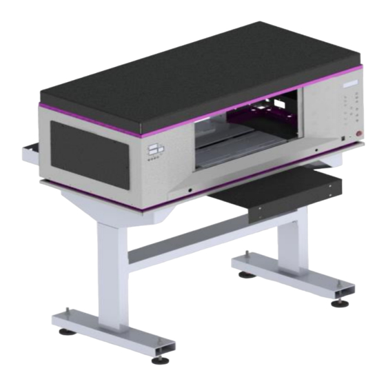
- Page 3 TABLE 1. Attach the LEFT and RIGHT support pieces to the MIDDLE SUPPORT (table) using 8 M8 SCREWS (image 1). 2. Place 2 BOTTOM SUPPORT pieces inside the left and right supports (image 2). 3. Place 4 LEVELING FEET and tightening them with 4 M10 NUT (image 3). Image 1 Image 2 PART NAME...
- Page 4 4. Assemble the LEFT and RIGHT brackets to the DTF machine using 4 M8 SCREW (image 4) 5. DISASSEMBLE the screws placed in the black upper base on the DTF and use them to assemble the UNION BRIDGE piece. (image 5)
- Page 5 6. Assemble the LEFT SUPPORT and RIGHT SUPPORT parts at the rear of the machine using 8 M5 SCREWS for the side walls and 2 M5 SCREWS for the bottom wall (image 7 & 8) 7. On the first lower opening of the LEFT and RIGHT Support bracket mount the piece DTF ROLL, LEFT ROLL SUPPORT (DTF) and RIGHT ROLL SUPPORT (DTF) (image 9)
- Page 6 8. Assemble a DTF ROLL piece in the free hole so that it passes through the holes of the LEFT and RIGHT ROLL SUPPORT (DTF) pieces (image 10) 9. Place the COLD FILM on the LEFT and RIGHT ROLL SUPPORT (DTF) pieces (image 11) 10.
- Page 7 11. Pass the COLD FILM over the Rear opening of the DTF machine and CAREFULLY move the yellow plate back (image 12) NOTE: this yellow plate will cause the BLACK ROLLERS to rise and the COLD FILM can pass over the machine until it reaches the front.
- Page 8 HEATER 14. Attach 2 BOTTOM SUPPORT HEATER pieces to the MIDDLE SUPPORT (Heater) using 8 M8 SCREWS (image 15 & 16). 15. Assemble 4 LEVELING FEET pieces and tighten using 4 M10 NUT (image 17) Image 15 Image 16 PART NAME DESCRIPTION Bottom Support Heater...
- Page 9 16. Assemble the HEATER on the 2 BOTTOM SUPPORT using 8 FLANGED BUTTON SCREW and 8 WASHERS (image 18) NOTE: CAREFULLY place the heater upside down on a table to be able to assemble the screws easily. 17. CAREFULLY turn the heater back over and attach the ROLL to the LEFT and RIGHT HANDLE pieces using 2 M6 SCREW (image 19) 18.
- Page 10 19. Insert the BRIDGE part inside the HEATER (image 21) 20. Remove the 2 screws found on the black plate of the DTF and put them back to assemble the BRIDGE part (image 22) 21. Assemble the UNION BRIDGE piece to the HEATER using 4 M6 Flanged Button Screw (image 23)
- Page 11 22. Tuck all the HEATER and the RIGHT ROLLER BRACKET cables inside the RIGHT HANDLE (image 24) 23. Mount the CORE on the RIGHT and LEFT ROLL SUPPORT pieces (image 25) 24. Raise the lid of the HEATER and place the FILM placed in step 11-13 on the plate. (image 26) 25.
Need help?
Do you have a question about the DTF and is the answer not in the manual?
Questions and answers