
Related Manuals for OmniPrint OM9300


Summary of Contents for OmniPrint OM9300
- Page 1 OM9300 Thermal Receipt printer Technical Manual Revision: 1.0 January 9, 2018 Omniprint Inc. 1923 East Deere Ave., Santa Ana, California 92705, U.S.A. T: 949.833.0080 F: 949.833.0040 www.omniprintinc.com...
-
Page 2: Table Of Contents
TABLE OF CONTENTS 1. General Specifications Printing Specifications Character Specifications Auto Cutter Paper Roll Supply Device Paper Specifications Printable Area Printing and Cutting Positions Internal Buffer Electrical Characteristics EMI and Safety Standards Applied Reliability Environmental Conditions 2. Configuration Interface RS-232 serial interface Specifications Switching between on-line and off-line Interface connector terminal assignments and signal functions... -
Page 3: General Specifications
1. General Specifications 1.1 Printing Specifications 1) Printing method: Thermal line printing 2) Dot density: 203dpi × 203dpi. The number of dots per 25.4mm(1") 3) Printing direction: Unidirectional with friction feed 4) Printing width: 75mm (2.83"), 576 dot positions 5) Characters per line: Font A: 12 x 24 dots, or 48 CPL (default) Font B: 9 x 17 dots, or 64 CPL... -
Page 4: Auto Cutter
3) Character size: Double-width / Standard Double-height Double-width Double-height WⅹH WⅹH WⅹH WⅹH Font A 12ⅹ24 1.25ⅹ3.39 1.25ⅹ 6.77 2.5ⅹ3.39 2.5ⅹ6.77 Font B 9ⅹ24 0.875ⅹ 3.39 0.875ⅹ6.77 1.75ⅹ3.39 1.75ⅹ6.77 Chinese 3ⅹ3.39 3ⅹ6.77 6ⅹ3.39 6x6.77 24ⅹ24 Space between characters is not included. CPL = Characters per line Measurements in mm 1.3 Auto Cutter... -
Page 5: Printable Area
1.6 Printable Area 1) Paper roll The printable area of a paper with width of 79.5± 0.5mm(3.13"±0.02") is 72.2 ± 0.2mm(2.84"±0.008")(576dots) and the space on the right and left sides are approximately 3.7 ± 2mm(0.15"±0.079"). a=79.5±0.5mm(3.13"±0.02") b=0.125mm±0.05mm(.056"±.002") c=69mm±0.2mm(2.84±.008") d=3.7±0.2mm(0.15"±0.079") □□□……………□□ e=3.7±0.2mm(0.15"±0.079") [All the numeric values are typical.] <... -
Page 6: Emi And Safety Standards Applied
1.10 EMI and Safety Standards Applied 1) Europe: EMI – EN55022 CLASS A EMS – EN61000-3-2 EN61000-3-3 EN50082-1 Safety Standard: EN60950 2) North America: EMI - FCC Part#15 Class A Safety Standards- UL(1950), c-UL(No.950) 1.11 Reliability 1) MCBF: 200 million lines (based on an average printing rate of 12.5% with paper thickness in the range 65 ㎛... -
Page 7: Configuration
2. Configuration 2.1 Interface 2.1.1 RS-232 serial interface 2.1.2 Specifications Data transmission: Serial Synchronization: Asynchronous Handshaking: DTR/DSR or XON/XOFF control Signal levels: MARK= -3 to –15V: Logic “1” SPACE= +3 to +15V: Logic “0” Baud rage: 9600, 19200, 38400, 115200 bps Data word length: 7 or 8 bits Parity Settings:... -
Page 8: Serial Interface Connection Example
2.1.5 Serial interface connection example Host side Printer side TXD ………………………………… RXD DSR ………………………………… DTR RXD ………………………………… TXD DTR ………………………………… DSR FG ………………………………… FG SG ………………………………… SG NOTES: ◦Set the handshaking so that the transmit data can be received. ◦Transmit data to the printer after turning on the power and initializing the printer. -
Page 9: Interface Connector
2.1.6 Centronics parallel interface SIGNAL DESCRIPTION STROBE- Input Synchronize signal Data received DATA0-7 Input Data bit Transmitted 0-7 ACK- Output Data receiving competed BUSY Output Impossible to printer data receiving Output Paper empty SELECT Output Printer’s status for ON/OFF line AUTO FEED- Input GROUND... -
Page 10: Data Receiving Timing(Compatibility Mode)
2.1.8 Parallel Interface 1) Specifications Data transmission: 8-bit parallel Synchronization: STROBE pulse supplied by host computer. Handshaking: ACK and BUSY Connector: D-SUB 25(male) or equivalent DATA Data n Data n+1 THold-1 nStrobe tSetup tSTB tHold-2 Busy Peripheral Busy tReady tBUSY nAck tReply tACK tnBUSY... -
Page 11: Connectors
3. Connectors 3.1 Interface Connectors Refer to Section 2.1, Interface 3.2 Electrical Characteristics 1) Input Voltage: DC 24V ± 10% 2) Current Consumption: Operating: Approx. 1.5 A (at ASC∥ printing) Peak: Approx. 10 A (at print duty 100%, For 10 seconds or less) Stand-by: Approx. -
Page 12: Drawer Kick-Out Connector (Modular Connector)
-Ethernet Interface SIGNAL Data Out + Output Data + Data Out - Output Data - Ground Data IN + Input Data + Data IN - Input Data - 3.4 Drawer Kick-out Connector (Modular Connector) The pulse specified by ESC p or DLE DC4 is output to this connector. The host can confirm the status of the input signal by using the DLE EOT, GS a, or GS r commands. - Page 13 CAUTION: To avoid an over current situation, the resistance of the drawer kick-out solenoid must be 24 Ω or more. Output waveform: The output shown in Figure 3.2 are inputs to points A and B in Figure 3.3 t1 (ON time) and t2 (OFF time) are specified by ESC p or DLE DC4.
-
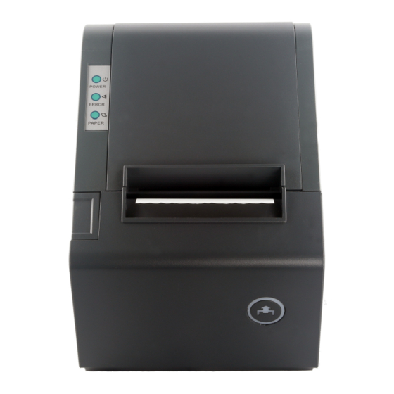
Page 14: Printer Appearance
4. Printer Appearance OM9300F Technical Manual Rev. Document No.: 19B00270 Date: Jan 09, 2018 Page: 14... -
Page 15: Paper Loading
Switch and LED Functions 1. FEED Button Press to feed paper manually; release to stop feeding. 2. Paper Status When both Error and Paper LEDs are on, printer is out of paper. When both Error and Paper LEDs are off, printer has paper. When only the Paper LED is on, paper is low. - Page 16 “1” “5” “6” OM9300F Technical Manual Rev. Document No.: 19B00270 Date: Jan 09, 2018 Page: 16...
-
Page 17: Dip Switch Setting
6. Dip Switch Setting the Dip Switch An 8 position DIP switch is located on the bottom of the printer unit. Gently turn the printer over and use a small Philips screw driver to remove the cover. By changing the switch positions you can modify the default setting for various functions such as cutter mode, character set, beeper, printer speed etc. - Page 18 Self Test You can perform a self test to determine the default settings and obtain the printer revision number. First, make sure the printer is turned off and then while pressing the Paper Feed button turn the printer on. The printer starts printing its factory setting. Example Only Code Page Setting: Refer to the Self Test page code details, for example:...
-
Page 19: Control Command Summary
Control command summary Command Function Horizontal tab Print and line feed Print and carriage return Print end position label to start printing Cancel print data in page mode DLE EOT Real-time status transmission DLE ENQ Real-time request to printer DLE DC4 Generate pulse at real-time ESC FF Print data in page mode... - Page 20 GS ! Select character size GS $ Set absolute vertical print position in page mode GS * Define downloaded bit image GS / Print down-loaded bit image GS : Start/end macro definition GS B Turn white/black reverse printing mode on/off GS H Select printing position of HRI characters GS I...
- Page 21 Example of using the commands. The numbers denoted by <>H is hexadecimal. The numbers denoted by <>B is binary. Print Commands Please see OMNIPrint Printer Control Command Set document for detailed explanation of the command codes. OM9300F Technical Manual Rev.
- Page 22 Consult your authorized reseller or service representative for help. § Properly shielded and grounded cables and connectors must be used in order to meet FCC emission limits. Proper cables and connectors are available from OMNIPRINT INC. authorized dealers. INDUSTRY CANADA CLASS A EMISSION COMPLIANCE STATEMENT This Class A digital apparatus meets all the requirements of the Canadian Interference- Causing Equipment Regulations.
- Page 23 Voltage Directive 73/23/EEC and Electromagnetic Compatibility Directive 89/336/ECC on the approximation of the laws of the member states of the EEC Commission. OMNIPRINT INC. cannot accept responsibility for any failure to satisfy the protection requirements resulting from a non-recommended modification of the product.
Need help?
Do you have a question about the OM9300 and is the answer not in the manual?
Questions and answers