
Related Manuals for OmniPrint OM9500-II


Summary of Contents for OmniPrint OM9500-II
- Page 1 OM9500-II Thermal Receipt printer Technical Manual Revision: 1.51 January 8, 2018 Omniprint Inc. 1923 East Deere Ave., Santa Ana, California 92705, U.S.A. T: 949.833.0080 F: 949.833.0040 www.omniprintinc.com...
-
Page 2: Table Of Contents
Data Receiving Timing(Compatibility Mode) 3. Connectors Interface Connectors Electrical Characteristics Drawer kick-out Connector (Modular Connector) 4. Printer Appearance 5. Paper Loading 6. Dip Switch Setting Control Command Summary OM9500-II Technical Manual Rev. Date: January 08, Document No.: 19B00260 Page: 2 1.51 2018... -
Page 3: General Specifications
8) Paper feed speed: Approximately 250mm/second (approximately 12 inches/second) (continuous paper feeding) 9) Line spacing (default): 1/6 inch (4.23mm) Programmable by control command. OM9500-II Technical Manual Rev. Date: January 08, Document No.: 19B00260 Page: 3 1.51 2018... -
Page 4: Character Specifications
Adjusting screw d) Remaining amount: Fixed position (approximately 23mm(0.9″)) (approximately 27mm(1.06″)) NOTE: You can use a command to stop printing upon detection of a paper near-end. OM9500-II Technical Manual Rev. Date: January 08, Document No.: 19B00260 Page: 4 1.51 2018... -
Page 5: Paper Specifications
Take the notice into account when setting the cutting position of the auto-cutter. 1.8 Internal Buffer 1) Receive buffer: 8kbyte OM9500-II Technical Manual Rev. Date: January 08, Document No.: 19B00260 Page: 5 1.51... -
Page 6: Electrical Characteristics
(based on an average printing rate of 12.5% with paper thickness in the range 76 ㎛ to 150 ㎛) 2) Cutter Life: 10.0 million cuttings (if the paper thickness is between 65 and 100 ㎛) OM9500-II Technical Manual Rev. Date: January 08, Document No.: 19B00260 Page: 6 1.51... -
Page 7: Environmental Conditions
Stop bits: 1 or 2 Connector (printer side): Female DB-9 pin connector NOTE: The data word length, baud rate, and parity depend on the DIP switch settings. OM9500-II Technical Manual Rev. Date: January 08, Document No.: 19B00260 Page: 7 1.51 2018... -
Page 8: Switching Between On-Line And Off-Line
Printer transmit data line RS-232C level Printer receive data line RS-232C level Output Printer handshake to host line RS-232C level Input Data Send Ready System Ground OM9500-II Technical Manual Rev. Date: January 08, Document No.: 19B00260 Page: 8 1.51 2018... -
Page 9: Serial Interface Connection Example
< Figure 2.1 Serial transmission bit frame > "1" "0" buffer emptied buffer full "1" "0" ready busy ready busy < Figure 2.2 Line transmission with protocol > OM9500-II Technical Manual Rev. Date: January 08, Document No.: 19B00260 Page: 9 1.51 2018... -
Page 10: Interface Connector
System Ground INIT- Input Initialize ERROR- Output Printer Error GROUND System Ground SELECT IN- Input 2.1.7 Interface Connector <D-SUB 9 Female Serial Port> <D-SUB Centronics Parallel Port> OM9500-II Technical Manual Rev. Date: January 08, Document No.: 19B00260 Page: 10 1.51 2018... -
Page 11: Data Receiving Timing(Compatibility Mode)
∞ ACKNLG Pulse Width tACK 10 ㎲ BUSY Release Time tnBUSY ∞ ACK Cycle Idle Time tNEXT *The printer latches data at a nStrobe ↓timing OM9500-II Technical Manual Rev. Date: January 08, Document No.: 19B00260 Page: 11 1.51 2018... -
Page 12: Connectors
3.3 USB and Ethernet Connection USB Connector Ethernet Connector -USB Interface SIGNAL DESCRIPTION DATA- Printer transmit data line DATA+ Printer transmit data line System Ground -Ethernet Interface SIGNAL OM9500-II Technical Manual Rev. Date: January 08, Document No.: 19B00260 Page: 12 1.51 2018... -
Page 13: Drawer Kick-Out Connector (Modular Connector)
Signal GND +24V is output through pin 4 when the power is turned on. However, pin 4 must by used only for the drawer. < Figure 3.1 Drawer Kick-out Connector > OM9500-II Technical Manual Rev. Date: January 08, Document No.: 19B00260 Page: 13 1.51... - Page 14 5. The resistance of the drawer kick-out solenoid must not be less than the specified. Otherwise, an over current could damage the solenoid. 6. Do not connect telecommunication network to the drawer kick-out connector OM9500-II Technical Manual Rev. Date: January 08, Document No.: 19B00260...
-
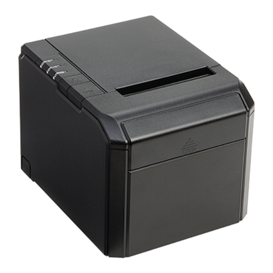
Page 15: Printer Appearance
4. Printer Appearance Latch Power Switch OM9500-II Technical Manual Rev. Date: January 08, Document No.: 19B00260 Page: 15 1.51 2018... - Page 16 When Power LED is on, printer is turned on. When Power LED is off, printer is turned off. 4. Error Indicator The LED blinks when there is a paper out, cutter error, or print head overheat condition. OM9500-II Technical Manual Rev. Date: January 08, Document No.: 19B00260 Page: 16 1.51...
-
Page 17: Paper Loading
8. Tear the excess paper against the serrated edge. 9. To reorder paper, please use part number: TP-80-230. Latch OM9500-II Technical Manual Rev. Date: January 08, Document No.: 19B00260 Page: 17 1.51... -
Page 18: Dip Switch Setting
NOTES: 1. To change the printer setting please make sure the power is turned off. 2. When changing the baud rate, make sure the host and printer baud rates match. OM9500-II Technical Manual Rev. Date: January 08, Document No.: 19B00260 Page: 18 1.51... - Page 19 Refer to the Self Test page code details, for example: For English: Select Page 0 For Russian: PC868 Chinese: Two Byte Character Code, SW-4 must be OFF OM9500-II Technical Manual Rev. Date: January 08, Document No.: 19B00260 Page: 19 1.51 2018...
-
Page 20: Control Command Summary
Enable/disable panel buttons ESC d Print and feed paper n lines ESC p General pulse ESC t Select character code table ESC { Set/cancel upside-down character printing OM9500-II Technical Manual Rev. Date: January 08, Document No.: 19B00260 Page: 20 1.51 2018... - Page 21 Transmit status GS v 0 Print raster bit image GS w Set bar code width < Add > ESC I Full cut ESC m Partial cut OM9500-II Technical Manual Rev. Date: January 08, Document No.: 19B00260 Page: 21 1.51 2018...
- Page 22 Example of using the commands. The numbers denoted by <>H is hexadecimal. The numbers denoted by <>B is binary. Print Commands Please see OMNIPrint Printer Control Command Set document for detailed explanation of the command codes. OM9500-II Technical Manual Rev.
- Page 23 Consult your authorized reseller or service representative for help. Properly shielded and grounded cables and connectors must be used in order to meet FCC emission limits. Proper cables and connectors are available from OMNIPRINT INC. authorized dealers. INDUSTRY CANADA CLASS A EMISSION COMPLIANCE STATEMENT This Class A digital apparatus meets all the requirements of the Canadian Interference- Causing Equipment Regulations.
- Page 24 Voltage Directive 73/23/EEC and Electromagnetic Compatibility Directive 89/336/ECC on the approximation of the laws of the member states of the EEC Commission. OMNIPRINT INC. cannot accept responsibility for any failure to satisfy the protection requirements resulting from a non-recommended modification of the product.
Need help?
Do you have a question about the OM9500-II and is the answer not in the manual?
Questions and answers