Table of Contents
Advertisement
Available languages
Available languages
Quick Links
Advertisement
Chapters
Table of Contents

Related Manuals for EKOM DK50 PLUS/M Series


Summary of Contents for EKOM DK50 PLUS/M Series
- Page 1 DK50 PLUS/M DK50 2V/M User manual Benutzerhandbuch Návod na použitie...
- Page 3 COMPRESSOR DK50 PLUS KOMPRESSOR DK50 2V KOMPRESOR EKOM spol. s r. o. Priemyselná 5031/18 SK-921 01 Piešťany Slovak Republic tel.: +421 33 7967255 fax: +421 33 7967223 www.ekom.sk email: ekom@ekom.sk DATE OF LAST REVISION DATUM DER LETZTEN ÜBERARBEITUNG 02/2020 DÁTUM POSLEDNEJ REVÍZIE...
- Page 4 CONTENTS ....................5 INHALT ......................49 OBSAH ......................94...
-
Page 5: Table Of Contents
CONTENTS CONTENTS GENERAL INFORMATION ......................6 CONFORMITY WITH THE REQUIREMENTS OF THE EUROPEAN UNION ....6 SYMBOLS ........................6 DEVICE USE ........................7 GENERAL SAFETY INSTRUCTION ................8 STORAGE AND TRANSPORT ..................9 PRODUCT DESCRIPTION ......................10 VARIANTS ........................10 ACCESORIES ........................ -
Page 6: General Information
GENERAL INFORMATION GENERAL INFORMATION Read the User manual carefully and keep it before use of the product. The User manual provides information on correct use – installation, operation and maintenance of the product. The User manual corresponds with the design of the product and condition according to the applicable safety and technical standards at the time of printing. -
Page 7: Device Use
GENERAL INFORMATION Package handling label – fragile Package handling label – this side up Package handling label – keep dry Package handling label – temperature limits Package handling label – limited stacking Package label – recyclable material Manufacturer 3. DEVICE USE 3.1. -
Page 8: General Safety Instruction
GENERAL INFORMATION 4. GENERAL SAFETY INSTRUCTION The product is designed and manufactured so that any risks connected with its use are minimized and the product is safe for the user and surrounding when used according to the intended use and the instructions stated below are followed. -
Page 9: Storage And Transport
GENERAL INFORMATION 5. STORAGE AND TRANSPORT The manufacturer ships the compressor in a transport packaging. This protects the device from damage during transport. Risk of damage to pneumatic parts. The compressor may be transported only depressurized. Vent air pressure from the pressure tank and pressure hoses and drain condensate from the air tank before transporting the compressor. -
Page 10: Product Description
PRODUCT DESCRIPTION PRODUCT DESCRIPTION 6. VARIANTS The compressor is manufactured according to its intended application in the following variants: DK50 PLUS compressor on base for stand-alone room installations DK50 PLUS/M compressor on base with air dryer DK50 PLUS S compressor in cabinet with effective noise dampening for room installations DK50 PLUS S/M compressor in cabinet with air dryer DK50 2V... -
Page 11: Product Function
PRODUCT DESCRIPTION Filters set Compressor can be equipped with a filters set of outlet compressed air as required. Filters set may include pressure regulator. The sets of filters are suitable accessories for the compressors specified above. Pressure Type Filtration level /µm/ Article no. - Page 12 PRODUCT DESCRIPTION is automatically drained at regular intervals into the collecting bottle via the condensate drain solenoid valve (16). The dryer ensures continuous drying of the compressed air. The drain valve (7) drains condensate from the air tank when drying performance is checked. Compressed, oil-free filtered air is stored in the air tank ready for use.
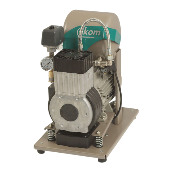
- Page 13 PRODUCT DESCRIPTION Fig. 1: DK50 PLUS – Compressor Description to Figures 1 - 3 Air pump Air tank Non-return valve Pressure switch Safety valve Pressure gauge Drain valve Inlet filter Dryer 10 – 11 – 12 – 13 Solenoid valve 14 Dryer cooler 15 Filter 16 Solenoid valve of condensate...
- Page 14 PRODUCT DESCRIPTION Fig. 2: DK50 2V/M – Compressor with dryer NP-DK50 PLUS, 2V-A-3_02-2020-MD 02/2020...
- Page 15 PRODUCT DESCRIPTION Fig. 3: – Cabinet 02/2020 NP-DK50 PLUS, 2V-A-3_02-2020-MD...
-
Page 16: Technical Data
TECHNICAL DATA TECHNICAL DATA Compressors are designed to operate in dry, ventilated and indoor dust-free rooms with the following climatic conditions: Temperature from +5°C to +40°C Relative humidity max. 70% Working pressure 5 – 7 bar DK50 PLUS DK50PLUS S DK50 PLUS/M DK50 PLUS S/M Nominal voltage... - Page 17 TECHNICAL DATA DK50 PLUS Working pressure 6 – 8 bar DK50 PLUS DK50PLUS S DK50 PLUS/M Nominal voltage 230, 115, 230, 115, 230, 230, 115, V, Hz Frequency 50/60 50/60 50/60 50/60 Capacity at 6 bar l/min 70/80 70/80 60/70 60/70 (FAD) 6.0 –...
- Page 18 TECHNICAL DATA Working pressure 8 – 10 DK50 PLUS DK50 PLUS DK50PLUS S DK50 PLUS/M Nominal voltage 230, 115, 230, 115, 230, 230, 115, V, Hz Frequency 50/60 50/60 50/60 50/60 Capacity at 8 bar l/min 60/70 60/70 50/60 50/60 (FAD) 8.0 –...
- Page 19 TECHNICAL DATA Working pressure 5 – 7 bar DK50 2V DK50 2V S DK50 2V/M DK50 2V S/M 230, 230, 230, 230, 230, 50 230, 50 230, 50 Nominal voltage 230,60 V, Hz 3x400, 3x400, 3x400, Frequency 115,60 115, 115, 3x400, 115, Capacity at 5 bar...
- Page 20 TECHNICAL DATA Working pressure 6 – 8 DK50 2V DK50 2V S DK50 2V/M DK50 2V S/M 230, 230, 50 230,50 230,50 230,50 Nominal voltage 230,60 230,60 230,60 V, Hz 3x400, 3x400, 3x400, 3x400, Frequency 115,60 115,60 115,60 115, Capacity at 6 bar l/min (FAD) Working...
- Page 21 TECHNICAL DATA Working pressure 8 – 10 DK50 2V DK50 2V S DK50 2V/M DK50 2V S/M 230, 230,50 230,50 230,50 230,50 230, Nominal voltage 230,60 , 60 V, Hz 3x400, 3x400, 3x400, 3x400, Frequency 115, 115,60 115,60 , 60 Capacity at 8 bar l/min (FAD)
- Page 22 TECHNICAL DATA FAD correction of capacity for altitude Capacity given in the form of FAD („Free Air Delivery“) applies to the following conditions: 20°C Altitude 0 m.n.m. Temperature Atmospheric pressure 101325 Pa Relative humidity To calculate FAD compressor capacity in dependence on altitude, it is necessary to apply correction factor according to the following table: Altitude [m.n.m.] 0 -1500...
-
Page 23: Installation
INSTALLATION INSTALLATION Risk of incorrect installation. Only a qualified professional can install the compressor and place it into operation for the first time His obligation is to train the operating personnel on the use and maintenance of the device. He shall confirm installation and training of operators by an entry into the installation record (see annex / anhang / príloha). - Page 24 INSTALLATION Prior to installation, ensure that the compressor is free of all transport packaging and stabilizers to avoid any risk of damage to the product Remove fixing elements of the pumps once the compressor has been assembled and balanced at the final installation place. Fig.
- Page 25 INSTALLATION Fig. 6: Changing door direction 02/2020 NP-DK50 PLUS, 2V-A-3_02-2020-MD...
- Page 26 INSTALLATION 10.3. Adding sound-insulating material into the cabinet A component from the sound-insulating material is to be installed in the opening of the cabinet of the compressor without a dryer. This component is provided in the basic equipment delivered with the product Fig.
-
Page 27: Pneumatic Connection
INSTALLATION 11. PNEUMATIC CONNECTION 11.1. Connecting to the compressed air outlet The pressure line (2) is attached to the compressed air outlet (1) on the compressor. Connect the drain hose (1) to the condensate vessel on compressors with dryers. - Page 28 INSTALLATION Fig. 10: Connection of condensate collection vessel Route the hose through the opening in the rear wall of the cabinet for compressors with dryers. Risk of damage to pneumatic components. Air hoses must not be broken. 11.4. Floor installation Connect the compressor using the hoses prepared in advance in the floor, as per the installation plan.
-
Page 29: Electrical Connection
INSTALLATION 12. ELECTRICAL CONNECTION The product is delivered with a cord equipped with a plug with earthing pin. Keep the socket easily accessible to ensure that the device can be safely disconnected from the mains. The corresponding circuit must be protected in the power distribution max. 16 A. Risk of electric shock. -
Page 30: Commissioning
INSTALLATION outlet while the latch is released. Fig. 13: Connecting a compressor installed in a cabinet 13. COMMISSIONING Check if all fixing elements used during transport have been removed. Check correct connection of compressed air (see chapter 11). ... -
Page 31: Pneumatic And Electrical Diagrams
INSTALLATION 14. PNEUMATIC AND ELECTRICAL DIAGRAMS 14.1. Pneumatic diagram DK50 PLUS, DK50 PLUS S, DK50 2V, DK50 2V S DK50 PLUS/M, DK50 PLUS S/M, DK50 2V/M, DK50 2V S/M Description to pneumatic diagrams Inlet filter 10 Air tank Compressor 11 Drain valve 12 Cooler Relief valve 13 Coalescing filter... - Page 32 INSTALLATION 14.2. Electrical diagrams DK50 PLUS, DK50 PLUS S DK50 2V, DK50 2V S 5 - 7 bar, 6 - 8 bar, 8 - 10 bar 1/N/PE 230 V, 50/60 Hz 115 V, 60 Hz ELECTRICAL OBJECT OF 1st. CAT DK50 PLUS/M, DK50 PLUS S/M DK50 2V/M, DK50 2V 5 - 7 bar, 6 - 8 bar, 8 - 10 bar 1/N/PE...
- Page 33 INSTALLATION DK50 2V, DK50 2V S 5 - 7 bar, 6 - 8 bar, 8 - 10 bar 3/N/PE 400 V, 50 Hz ELECTRICAL MAINS TN-S [TN-C-S] ELECTRICAL OBJECT OF 1st. CAT DK50 2V/M, DK50 2V S/M 5 - 7 bar, 6 - 8 bar, 8 - 10 bar 3/N/PE 400 V, 50 Hz ELECTRICAL MAINS TN-S [TN-C-S]...
- Page 34 INSTALLATION 8 – 10 bar Compressor cabinet 1/N/PE 230V, 50 Hz 230 V, 50 Hz, 230 V, 60 Hz ELECTRICAL OBJECT OF 1st. CAT Description to electrical diagrams Compressor motor Capacitor Compressor fan Pressure switch Dryer fan Terminal box Relief valve Circuit breaker switch Temperature switch Condensate drain valve...
-
Page 35: Operation
OPERATION OPERATION THE EQUIPMENT MAY ONLY BE OPERATED BY THE TRAINED STAFF! Risk of electric shock In case of any danger, disconnect the compressor from the mains (pull out the mains plug). Risk of burn or fire. During compressor operation, the pump parts may heat to temperatures dangerous for contact with persons or materials. -
Page 36: Switching On The Compressor
OPERATION 15. SWITCHING ON THE COMPRESSOR Start the compressor (without a cabinet) at the pressure switch (1) by turning the switch (2) to position “I.” This starts the compressor and fills the tank to the switching off pressure, which then shuts off the compressor. -
Page 37: Product Maintenance
PRODUCT MAINTENANCE PRODUCT MAINTENANCE 17. PRODUCT MAINTENANCE The operator should carry out device checks regularly in the intervals defined by applicable regulations. Test results must be recorded. The device has been designed and manufactured to keep its maintenance to a minimum. For correct and reliable operation of the compressor perform the following operations: Risk of servicing by persons without required qualification. - Page 38 PRODUCT MAINTENANCE 17.1. Maintenance intervals operator qualified technician NP-DK50 PLUS, 2V-A-3_02-2020-MD 02/2020...
- Page 39 PRODUCT MAINTENANCE 17.2. Check of product operation Check pump condition – the pumps must operate evenly without excessive vibrations or noise. If there is any negative result, find the cause of the given condition or call service engineers. Check fans operation (visually) –...
- Page 40 PRODUCT MAINTENANCE 17.5. Condensate drain Compressors Open the drain valve carefully and slowly. If the drain valve is opened too much, it is accompanied by high noise level and uncontrolled jet of the accumulated condensate Risk of slipping on a wet floor in case of the collecting vessel overflow. During regular operation, it is recommended to drain condensate from the pressure tank.
- Page 41 PRODUCT MAINTENANCE 17.6. Check of safety valve Turn the screw (2) on the safety valve (1) several times to the left until the safety valve releases the air. Let the safety valve vent for a few seconds. Turn the screw (2) fully to the right, the valve must be closed now.
- Page 42 PRODUCT MAINTENANCE Pull out the pre-filter by hand (3) Replace the element and re-insert Fig. 19: Inlet pre-filter replacement 17.8. Replacement of filter element Remove the tube (1) from the quick coupling. Loosen the filter bowl (3) using a wrench and dismantle. ...
- Page 43 PRODUCT MAINTENANCE 17.10. Procedure for connecting a compressor disconnected from the cabinet Prior to any maintenance or repair work, switch off the compressor and disconnect it from the mains (pull out the mains plug). The compressor (without cabinet) requires that the jumper is always mounted in the terminal strip for correct operation (Fig.
- Page 44 PRODUCT MAINTENANCE Fig. 21 230V NP-DK50 PLUS, 2V-A-3_02-2020-MD 02/2020...
- Page 45 PRODUCT MAINTENANCE Fig. 22 400V 17.11. Procedure for connecting a compressor to a new cabinet Prior to any maintenance or repair work, switch off the compressor and disconnect it from the mains (pull out the mains plug). The compressor in a cabinet requires that the jumper is not mounted in the terminal strip for correct operation (Fig.
-
Page 46: Long-Term Shutdown
PRODUCT MAINTENANCE PROCESS: Jumper removal (B-A process): Disconnect the product from the mains by pulling the plug out of the socket. Remove the cover on the electrical panel (on the compressor). The jumper is in the terminal strip – B ... -
Page 47: Troubleshooting
TROUBLESHOOTING TROUBLESHOOTING Risk of electric shock. Before any of the following operations on the device, disconnect the device from the mains (pull out the mains plug). Risk of injury during work with pneumatic components under pressure. Before any of the following operations on the device, it is necessary to decrease pressure in the air tank and in the pneumatic system to zero. -
Page 48: Repair Service
TROUBLESHOOTING compressor Worn piston ring Replace worn piston ring Dirty inlet filter Replace dirty filter with new filter Incorrect function of solenoid valve Repair or replace fan or coil Damaged piston bearing, piston Replace damaged bearing Compressor is rods, motor bearing noisy (knocking, Loose (cracked) dampening metal noises) - Page 49 INHAT INHAT ALLGEMEINE INFORMTIONEN ....................50 KONFORMITÄT MIT DEN ANFORDERUNGEN DER EU ..........50 SYMBOLE ........................50 NUTZUNG DES GERÄTS ....................51 ALLGEMEINE SICHERHEITSANWEISUNGEN ............. 52 LAGERUNGS- UND TRSANSPORTBEDINGUNGEN ........... 53 PRODUKTBESCHREIBUNG ....................... 54 MODELLE ........................54 ZUBEHÖR ........................54 PRODUKTFUNKTION ....................
-
Page 50: Allgemeine Informtionen
ALLGEMEINE INFORMTIONEN ALLGEMEINE INFORMTIONEN Lesen Sie das Benutzerhandbuch vor der Nutzung des Produkts sorgfältig durch und bewahren Sie es auf. Das Benutzerhandbuch enthält Anleitungen zur korrekten Nutzung, Installation, Bedienung und Wartung des Produkts. Zum Zeitpunkt des Drucks entspricht das Benutzerhandbuch dem Produktdesign und erfüllt die geltenden Sicherheits- und Technikstandards. -
Page 51: Nutzung Des Geräts
ALLGEMEINE INFORMTIONEN Sicherung Etikett für die Handhabung der Verpackung – zerbrechlich Etikett für die Handhabung der Verpackung – diese Seite nach oben Etikett für die Handhabung der Verpackung – trocken halten Etikett für die Handhabung der Verpackung – Temperaturlimits Etikett für die Handhabung der Verpackung – Stapelbeschränkung Verpackungsetikett –... -
Page 52: Allgemeine Sicherheitsanweisungen
ALLGEMEINE INFORMTIONEN 4. ALLGEMEINE SICHERHEITSANWEISUNGEN Das Produkt wurde entwickelt und hergestellt, um alle Risiken in Verbindung mit seiner Nutzung zu minimieren. Das Produkt ist für den Benutzer und für die Umgebung sicher, wenn es gemäß seinem Verwendungszweck und den nachfolgend aufgeführten Anweisungen verwendet wird. 4.1. -
Page 53: Lagerungs- Und Trsansportbedingungen
ALLGEMEINE INFORMTIONEN 5. LAGERUNGS- UND TRSANSPORTBEDINGUNGEN Der Hersteller versendet den Kompressor in einer Transportverpackung. Diese schützt das Gerät während des Transports vor Schäden. Beschädigungsgefahr für Pneumatikteile. Der Kompressor darf nur drucklos transportiert werden. Lassen Sie die Druckluft aus dem Druckluftbehälter und den Druckluftschläuchen ab und entleeren Sie das Kondensat aus dem Druckluftbehälter, bevor Sie den Kompressor transportieren. -
Page 54: Produktbeschreibung
PRODUKTBESCHREIBUNG PRODUKTBESCHREIBUNG 6. MODELLE Der Kompressor wurde gemäß seinem Verwendungszweck in den folgenden Modellen erbaut: Kompressor auf Sockel für unabhängige Installation in Räumen DK50 PLUS DK50 PLUS/M Kompressor auf Sockel mit Lufttrockner Kompressor in einem Gehäuse mit effektiver Geräuschdämpfung für den DK50 PLUS S Einbau in Räumen Kompressor in Gehäuse mit Lufttrockner... - Page 55 PRODUKTBESCHREIBUNG Filter set Bei Bedarf kann der Kompressor mit einem Filter-Kit am Druckluftausgang ausgestattet werden. Das Filter-Kit kann einen Druckregler umfassen. Die Filtersätze sind ein geeignetes Zubehör für alle oben aufgeführten Kompressoren. HINWEIS: Ist ein anderer Grad an Luftfilterung nötig, muss dies mit dem Lieferanten vereinbart und in der Bestellung klar angegeben werden.
-
Page 56: Produktfunktion
PRODUKTBESCHREIBUNG 8. PRODUKTFUNKTION 8.1. Kompressor Abb. 1 Die Kompressorpumpe (1) saugt die Außenluft durch den Ansaugfilter (8) an und komprimiert sie durch das Absperrventil (3) in den Druckluftbehälter (2), von dem aus das Gerät die Druckluft bezieht. Fällt der Druck im Druckluftbehälter auf den Einschaltdruck ab, schaltet der Druckschalter (4) den Kompressor ein und der Kompressor verdichtet die Luft in dem Druckluftbehälter, bis der Ausschaltdruck erreicht wird und der Kompressor abschaltet. - Page 57 PRODUKTBESCHREIBUNG Überhitzungsgefahr des Kompressors. Stellen Sie sicher, dass keine Blockaden am Einlass der Kühlluft in das Gehäuse (im Bodenbereich des Gehäuses) und am Auslass der Warmluft an der Hinterseite des Gehäuses im oberen Bereich bestehen. Wird der Kompressor auf eine weiche Unterlage gestellt (z.B. auf einen Teppich), schaffen Sie einen Abstand zwischen der Basis und dem Boden oder dem Gehäuse und dem Boden, indem die Füße z.B.
- Page 58 PRODUKTBESCHREIBUNG Abb. 2: DK50 2V/M – Kompressor mit Trockner NP-DK50 PLUS, 2V-A-3_02-2020-MD 02/2020...
- Page 59 PRODUKTBESCHREIBUNG Abb. 3: – Kompressorgehäuse 02/2020 NP-DK50 PLUS, 2V-A-3_02-2020-MD...
-
Page 60: Technische Daten
TECHNISCHE DATEN TECHNISCHE DATEN Die Kompressoren sind für den Betrieb in trockenen, belüfteten und staubfreien Innenräumen mit den folgenden klimatischen Bedingungen vorgesehen: von +5 °C bis +40 °C Temperatur Relative Feuchtigkeit max. 70 % Arbeitsdruck 5 – 7 bar DK50 PLUS DK50PLUS S DK50 PLUS/M DK50 PLUS S/M... - Page 61 TECHNISCHE DATEN DK50 PLUS Arbeitsdruck 6 – 8 bar DK50 PLUS DK50PLUS S DK50 PLUS/M Nennspannung 230, 230, 230, 230, V, Hz 115,60 115,60 115,60 115,60 Frequenz 50/60 50/60 50/60 50/60 Kapazität bei 6 l/min 70/80 70/80 60/70 60/70 bar (FAD) 6,0 –...
- Page 62 TECHNISCHE DATEN DK50 PLUS Arbeitsdruck 8 – 10 bar DK50 PLUS DK50PLUS S DK50 PLUS/M Nennspannung 230, 115, 230, 115, 230, 230, 115, V, Hz Frequenz 50/60 50/60 50/60 50/60 Kapazität bei 8 bar l/min 60/70 60/70 50/60 50/60 (FAD) 8,0 –...
- Page 63 TECHNISCHE DATEN Arbeitsdruck 5 – 7 bar DK50 2V DK50 2V S DK50 2V/M DK50 2V S/M 230, 230, 230, 230, 230, 230, 50 230, 50 230, 50 Nennspannung V, Hz 3x400, 3x400, 3x400, Frequenz 115, 115, 115, 3x400, 115, Kapazität bei 5 bar l/min (FAD)
- Page 64 TECHNISCHE DATEN Arbeitsdruck 6 – 8 bar DK50 2V DK50 2V S DK50 2V/M DK50 2V S/M 230, 230,50 230,50 230,50 230,50 Nennspannung 230,60 230,60 230,60 V, Hz 3x400, 3x400, 3x400, 3x400, Frequenz 115/60 115,60 115,60 115, Kapayität bei 6 l/min bar (FAD) 6,0 –...
- Page 65 TECHNISCHE DATEN Arbeitsdruck 8 – 10 bar DK50 2V DK50 2V S DK50 2V/M DK50 2V S/M 230, 230, 230, 230, 230,50 230,50 230,60 230,50 Nennspannung V, Hz 3x400, 3x400, 115, 3x400, Frequenz 115, 115, 3x400, 115, Kapazität bei 8 bar l/min (FAD) 8,0 –...
- Page 66 TECHNISCHE DATEN FAD-Kapazitätskorrektur für Höhenlagen Die Kapazität in Form von FAD („Free Air Delivery“, freie Druckluftversorgung) gilt für die folgenden Bedingungen: Höhenlage 20 °C 0 m.n.m. Temperatur Umgebungsdruck 101325 Pa Relative Feuchtigkeit Um die FAD-Kompressorkapazität in Abhängigkeit von der Höhenlage zu berechnen, muss der Korrekturfaktor gemäß...
-
Page 67: Installation
INSTALLATION INSTALLATION Risiko von Installationsfehlern. Der Kompressor darf ausschließlich durch eine hierfür qualifizierte Fachkraft installiert Betrieb genommen werden Dieser verpflichtet, professionelles Bedienpersonal bzgl. der Nutzung und Wartung des Geräts zu schulen. Er wird die Installation sowie die Schulung der Bediener durch einen Eintrag in das Installationsprotokoll (siehe annex / anhang / príloha) bestätigen. - Page 68 INSTALLATION Stellen Sie vor der Installation sicher, dass der Kompressor frei von Verpackungsmaterial und Stabilisatoren ist, um Schäden am Produkt zu vermeiden. Entfernen Sie die Befestigungselemente der Pumpen, nachdem der Kompressor zusammengebaut und am endgültigen Aufstellungsort nivelliert wurde. Abb. 5: Freischalten der Pumpe 10.2.
- Page 69 INSTALLATION Abb. 6: Ändern der Türöffnungsrichtung 02/2020 NP-DK50 PLUS, 2V-A-3_02-2020-MD...
- Page 70 INSTALLATION 10.3. Gehäuseeinbau von Schallschutzmaterial Ein Bauteil aus Schallschutzmaterial ist in die Gehäuseöffnung des Kompressors ohne Trockner einzubauen. Dieses Teil ist in der mit dem Produkt gelieferten Grundausstattung enthalten. Abb. 7: Gehäuseeinbau von Schallschutzmaterial NP-DK50 PLUS, 2V-A-3_02-2020-MD 02/2020...
-
Page 71: Pneumatischer Anschluss
INSTALLATION 11. PNEUMATISCHER ANSCHLÜSSE 11.1. Anschluss an den Druckluftausgang Druckleitung Druckluftauslass (1) am Kompressor Schließen befestigt. Kompressoren Trocknern Kondensatablaufschlauch (1) an den Kondensatbehälter an. Abb. 8: Anschluss an den Druckluftausgang Führen Sie bei Kompressoren mit Gehäuseeinbau den Druckluftschlauch durch die Öffnung an der Rückwand des Gehäuses (Abb. - Page 72 INSTALLATION 11.3. Anschluss des Kondensatauffangbehälter Schließen Sie bei Kompressoren mit Gehäuseeinbau den Kondensatablaufschlauch an die Kondensatauffangbehälter (Abb. 10) an. Abb. 10: Anschluss des Kondensatbehälters Führen Sie bei Kompressor-Modellen mit Trockner den Schlauch durch die Öffnung an der Rückwand des Gehäuses und verbinden Sie ihn mit dem Behälter. Beschädigungsgefahr für Pneumatikkomponenten.
-
Page 73: Elektrischer Anschluss
INSTALLATION 12. ELEKTRISCHER ANSCHLUSS Das Produkt wird mit einem Kabel mit Stecker und Erdungsstift geliefert. Die Steckdose muss leicht zugänglich sein, damit das Gerät sicher vom Strom getrennt werden kann. Der entsprechende Schaltkreis muss in der Stromverteilung mit max. 16A geschützt sein. Stromschlaggefahr. -
Page 74: Inbetriebnahme
INSTALLATION indem Sie den Stecker (1) aus der Steckdose ziehen, während die Verriegelung gelöst ist. Abb. 13: Anschließen eines Kompressors mit Gehäuse 13. INBETRIEBNAHME Überprüfen Sie, ob alle für den Transport verwendeten Befestigungselemente entfernt wurden. Überprüfen Sie den Druckluftanschluss (siehe Kapitel 11). ... -
Page 75: Druckluft- Und Elektroschaltpläne
INSTALLATION 14. DRUCKLUFT- UND ELEKTROSCHALTPLÄNE 14.1. Druckluftplan DK50 PLUS, DK50 PLUS S, DK50 2V, DK50 2V S DK50 PLUS/M, DK50 PLUS S/M, DK50 2V/M, DK50 2V S/M Beschreibung des Druckluftplans: 10 Druckluftbehälter Ansaugfilter Kompressor 11 Ablassventil Lüfter 12 Kühler Entlüftungsventil 13 Koaleszenzfilter Schalldämpfer 14 Membrantrockner... - Page 76 INSTALLATION 14.2. Elektroschaltpläne DK50 PLUS, DK50 PLUS S DK50 2V, DK50 2V S 5 - 7 bar, 6 - 8 bar, 8 - 10 bar 1/N/PE 230 V, 50/60 Hz 115 V, 60 Hz ELEKTRISCHE OBJEKTKLASSE 1 DK50 PLUS/M, DK50 PLUS S/M DK50 2V/M, DK50 2V 5 - 7 bar, 6 - 8 bar, 8 - 10 bar 1/N/PE 230 V, 50/60 Hz...
- Page 77 INSTALLATION DK50 2V, DK50 2V S 5 - 7 bar, 6 - 8 bar, 8 - 10 bar 3/N/PE 400 V, 50Hz NETZ TN-S [TN-C-S] ELEKTRISCHE OBJEKTKLASSE 1 DK50 2V/M, DK50 2V S/M 5 - 7 bar, 6 - 8 bar, 8 - 10 bar 3/N/PE 400 V, 50 Hz NETZ TN-S [TN-C-S]...
- Page 78 INSTALLATION 8 – 10 bar Kompressorschrank 1/N/PE 230 V, 50 Hz ELEKTRISCHE OBJEKTKLASSE 1 Beschreibung der Elektroschaltpläne: Kompressormotor Kondensator Kompressorlüfter Druckschalter Trocknerlüfter Klemmblock Ablasssventil Trennschalter Temperaturschalter Kondensatablassventil Gehäuselüfter Stundenzähler X10,X2 Verbinder Schalter Sicherheitsschalter Anzeige Schutz Netzdose Hinweis: J** - Schließen Sie nur den Jumper für Kompressoren ohne Schrank an (siehe Kapitel. 17.10) ...
-
Page 79: Betrieb
BETRIEB BETRIEB DAS GERÄT DARF NUR DURCH GESCHULTES PERSONAL BEDIENT WERDEN! Stromschlaggefahr Trennen Sie bei Gefahr den Kompressor vom Stromnetz (Netzstecker ziehen). Verbrennungs- oder Brandgefahr. Während des Kompressorbetriebs können die Pumpenteile Temperaturen erreichen, die für den Kontakt mit Personen oder Materialien gefährlich sein können. -
Page 80: Einschalten Des Kompressors
BETRIEB 15. EINSCHALTEN DES KOMPRESSORS Starten Sie den Kompressor (ohne Gehäuse) am Druckschalter (1), indem Sie den Schalter (2) auf Position „I“ stellen. Dadurch wird der Kompressor gestartet und der Tank bis zum Ausschaltdruck gefüllt, wodurch der Kompressor abgeschaltet wird. Starten Sie den Kompressor (mit Gehäuse) über den Schalter (5) an der Vorderseite des Gehäuses. -
Page 81: Produktwartung
PRODUKTWARTUNG PRODUKTWARTUNG 17. PRODUKTWARTUNG Der Bediener muss die Geräte in den vorgeschriebenen Intervallen kontrollieren. Die Prüfergebnisse müssen aufgezeichnet werden. Das Gerät wurde konstruiert und hergestellt, um den Wartungsaufwand gering zu halten. Führen Sie die folgenden Schritte aus, um den korrekten und zuverlässigen Betrieb des Kompressors sicherzustellen: Die Instandhaltung durch Personen ohne die erforderliche Qualifikation birgt Risiken. - Page 82 PRODUKTWARTUNG Für Wartungs- oder Reparaturarbeiten kann der Kompressor aus dem Gehäuse herausgezogen werden (auf Lenkrollen und so weit, wie es das Kabel zwischen Kompressor und Schrank erlaubt; siehe auch Kap. 17). Danach können die erforderlichen Wartungs- oder Reparaturarbeiten durchgeführt werden. ...
- Page 83 PRODUKTWARTUNG 17.1. Wartungsintervalle Bediener Qualifizierter Techniker 02/2020 NP-DK50 PLUS, 2V-A-3_02-2020-MD...
- Page 84 PRODUKTWARTUNG 17.2. Produktbetrieb überprüfen Pumpenzustand prüfen – die Pumpen müssen normal, ohne übermäßige Schwingung oder Geräuschentwicklung laufen. Suchen Sie bei negativen Prüfergebnissen die Ursache dafür oder rufen Sie einen Servicetechniker. Kontrollieren Sie die Lüfterfunktion (visuell) – die Lüfter müssen bei Pumpenbetrieb laufen. Suchen Sie bei negativen Prüfergebnissen nach der Ursache dafür oder rufen Sie einen Servicetechniker.
- Page 85 PRODUKTWARTUNG Überprüfen Sie das Netzkabel und die Stromleiter auf Unversehrtheit. Überprüfen Sie, ob die Kabel am Anschlusskasten angeschlossen sind (Sichtprüfung). Überprüfen Sie alle Schraubverbindungen der grün-gelben PE-Erdungsleiter. 17.5. Kondensatablauf Kompressor Öffnen Sie das Ablassventil vorsichtig und langsam. Wird das Ablassventil zu weit geöffnet, ist ein sehr lauter Ton zu hören und das angesammelte Kondensat wird unkontrolliert ausgestoßen.
- Page 86 PRODUKTWARTUNG 17.6. Sicherheitsventil überprüfen Drehen Schraube Sicherheitsventil (1) mehrere Umdrehungen nach links, bis das Sicherheitsventil Luft ablässt. Sicherheitsventil einige Sekunden ausblasen lassen. Drehen Sie die Schraube (2) bis zum Anschlag nach rechts. Das Ventil muss jetzt geschlossen sein. Abb.
- Page 87 PRODUKTWARTUNG Ziehen Sie den Vorfilter mit der Hand heraus (3). Ersetzen Sie den Filter und setzen Sie ihn wieder ein. Abb. 19: Austausch des Vorfilters 17.8. Austausch des Filterelements Entfernen Sie den Schlauch (1) aus der Schnellkupplung. ...
- Page 88 PRODUKTWARTUNG Es ist notwendig, dass bei einem Kompressor (ohne Gehäuse) der Jumper immer an die Klemmleiste montiert wird, damit der ordnungsgemäße Betrieb gewährleistet ist (Abb. 21, Abb. 22, Pos. B). Dies ersetzt dann den Schalter am Gehäuse. Befindet sich kein Jumper auf der Klemmleiste, funktioniert der Kompressor nicht! Löst sich das Kabel zwischen Kompressor und Gehäuse (durch Ziehen des Netzsteckers) und wird der Kompressor aus dem Gehäuse entfernt, funktioniert der Kompressor nicht mehr.
- Page 89 PRODUKTWARTUNG Abb. 21 230V 02/2020 NP-DK50 PLUS, 2V-A-3_02-2020-MD...
- Page 90 PRODUKTWARTUNG Abb. 22 400V 17.11. Vorgehensweise Anschließen eines Kompressors an einen neuen Schaltschrank Vor jeder Wartungs- oder Reparaturarbeit ist der Kompressor auszuschalten und durch Ziehen des Netzsteckers vom Stromnetz zu trennen. Es ist notwendig, dass bei einem Kompressor (mit Gehäuse) der Jumper nicht an die Klemmleiste montiert wird, damit der ordnungsgemäße Betrieb gewährleistet ist (Abb.
-
Page 91: Langfristige Außerbetriebnahme
PRODUKTWARTUNG PROZESS: Entfernen des Jumpers (B-A Prozess): Trennen Sie das Gerät vom Stromnetz, indem Sie den Stecker aus der Steckdose ziehen. Entfernen Sie die Abdeckung von der Schalttafel (des Kompressors). Der Jumper befindet sich auf der Klemmleiste – B ... -
Page 92: Fehlerbehebung
FEHLERBEHEBUNG FEHLERBEHEBUNG Stromschlaggefahr Trennen Sie das Gerät von der Stromversorgung (Netzstecker ziehen), bevor Sie eine der folgenden Arbeiten am Gerät ausführen. Arbeiten Druckluftkomponenten unter Druck besteht Verletzungsgefahr. Bevor Sie eine der folgenden Arbeiten am Gerät ausführen, reduzieren Sie den Druck im Druckluftbehälter und im Pneumatiksystem auf null. Alle Arbeiten, um Fehler und Störungen zu beheben, dürfen nur durch einen qualifizierten Techniker ausgeführt werden. -
Page 93: Informationen Zu Reparaturbetrieben
FEHLERBEHEBUNG Niedrige Pumpenkapazität Pumpe reinigen oder austauschen Pumpenstörung Pumpe reinigen oder austauschen Trocknerstörung Trockner austauschen Pneumatiksystem überprüfen – lose Luftaustritt im Pneumatiksystem Verbindungen festziehen Betrieb des Kolbenring verschlissen Verschlissenen Kolbenring ersetzen Kompressors über Verschmutzten Filter durch neuen einen längeren Ansaugfilter verschmutzt Filter ersetzen Zeitraum Lüfter oder Spule reparieren oder... - Page 94 OBSAH OBSAH VŠEOBECNÉ INFORMÁCIE......................95 ZHODA S POŽIADAVKAMI SMERNÍC EURÓPSKEJ ÚNIE ...........95 POUŽITÉ SYMBOLY ......................95 POUŽITIE ZARIADENIA ....................96 ZÁKLADNÉ BEZPEČNOSTNÉ POKYNY ...............97 SKLADOVACIE A PREPRAVNÉ PODMIENKY ..............98 POPIS VÝROBKU ........................99 VARIANTY ........................99 DOPLNKOVÉ VYBAVENIE ....................99 FUNKCIA VÝROBKU ....................101 TECHNICKÉ ÚDAJE ......................... 105 INŠTALÁCIA ..........................
-
Page 95: Všeobecné Informácie
VŠEOBECNÉ INFORMÁCIE VŠEOBECNÉ INFORMÁCIE Návod na použitie si pred použitím výrobku starostlivo prečítajte a uschovajte. Návod na použitie slúži na správne používanie - inštaláciu, obsluhu a údržbu výrobku. Návod na použitie zodpovedá pri tlači vyhotoveniu výrobku a stavu podľa príslušných bezpečnostno-technických noriem. -
Page 96: Použitie Zariadenia
VŠEOBECNÉ INFORMÁCIE Manipulačná značka na obale – krehké Manipulačná značka na obale – týmto smerom nahor Manipulačná značka na obale – chrániť pred dažďom Manipulačná značka na obale – teplotné medze Manipulačná značka na obale – obmedzené stohovanie Značka na obale – recyklovateľný materiál Výrobca 3. -
Page 97: Základné Bezpečnostné Pokyny
VŠEOBECNÉ INFORMÁCIE 4. ZÁKLADNÉ BEZPEČNOSTNÉ POKYNY Výrobok je navrhnutý a vyrobený tak, aby boli minimalizované akékoľvek riziká spojené s jeho použitím a výrobok bol bezpečný pre používateľa aj pre okolie pri používaní podľa zamýšľaného použitia a dodržaní nasledujúcich pokynov. Požadovaná kvalifikácia personálu 4.1. -
Page 98: Skladovacie A Prepravné Podmienky
VŠEOBECNÉ INFORMÁCIE 5. SKLADOVACIE A PREPRAVNÉ PODMIENKY Kompresor sa od výrobcu zasiela v prepravnom obale. Tým je výrobok zabezpečený pred poškodením pri preprave. Nebezpečenstvo poškodenia pneumatických častí. Kompresor sa smie prepravovať len bez tlaku. Pred prepravou nevyhnutne vypustiť tlak vzduchu z tlakovej nádrže a tlakových hadíc a vypustiť kondenzát zo vzdušníka. -
Page 99: Popis Výrobku
POPIS VÝROBKU POPIS VÝROBKU 6. VARIANTY Kompresor sa vyrába podľa účelu v týchto variantoch: kompresor na základni na samostatné ustavenie v miestnosti DK50 PLUS kompresor na základni so sušičom vzduchu DK50 PLUS/M kompresor v skrinke s účinným tlmením hluku pre umiestnenie v ordinácii DK50 PLUS S kompresor v skrinke so sušičom vzduchu DK50 PLUS S/M... - Page 100 POPIS VÝROBKU Súprava filtrov Kompresor môže byť vybavený súpravou filtrov výstupného stlačeného vzduchu podľa požiadavky. Súprava filtrov môže obsahovať aj regulátor tlaku. Súpravy filtrov sú vhodné pre uvedené kompresory. POZNÁMKA: V prípade požiadavky na iný stupeň filtrácie vzduchu, je treba túto požiadavku dohodnúť...
-
Page 101: Funkcia Výrobku
POPIS VÝROBKU 8. FUNKCIA VÝROBKU 8.1. Kompresor Obr. 1 Agregát kompresora (1) nasáva atmosférický vzduch cez vstupný filter (8) a stláča ho cez spätný ventil (3) do vzdušníka (2) a spotrebič odoberá stlačený vzduch zo vzdušníka. Ak klesne tlak vo vzdušníku na zapínací tlak, tlakový spínač (4) zapne kompresor a kompresor stláča vzduch do vzdušníka až... - Page 102 POPIS VÝROBKU Obr. 1: DK50 PLUS – Kompresor Popis k obrázkom 1 - 3 Agregát kompresora Vzdušník Spätný ventil Tlakový spínač Poistný ventil Tlakomer Vypúšťací ventil Vstupný filter Sušič 10 - 11 - 12 - 13 Solenoidný ventil 14 Chladič sušiča 15 Filter 16 Solenoidný...
- Page 103 POPIS VÝROBKU Obr. 2: DK50 2V/M – Kompresor so sušičom MD 02/2020 NP-DK50 PLUS, 2V-A-3_02-2020-MD...
- Page 104 POPIS VÝROBKU Obr. 3: – Skrinka NP-DK50 PLUS, 2V-A-3_02-2020-MD 02/2020...
-
Page 105: Technické Údaje
TECHNICKÉ ÚDAJE TECHNICKÉ ÚDAJE Kompresory sú konštruované pre prevádzku v suchých, vetraných a bezprašných vnútorných priestoroch pri nasledujúcich klimatických podmienkach: +5°C až +40°C Teplota Relatívna vlhkosť max. 70% Pracovný tlak 5 – 7 bar DK50 PLUS DK50PLUS S DK50 PLUS/M DK50 PLUS S/M Menovité... - Page 106 TECHNICKÉ ÚDAJE DK50 PLUS Pracovný tlak 6 – 8 bar DK50 PLUS DK50PLUS S DK50 PLUS/M Menovité napätie 230, 230, 230, 230, V, Hz 115,60 115,60 115,60 115,60 Frekvencia 50/60 50/60 50/60 50/60 Výkonnosť pri pretlaku 6 bar l/min 70/80 70/80 60/70 60/70...
- Page 107 TECHNICKÉ ÚDAJE DK50 PLUS Pracovný tlak 8 – 10 bar DK50 PLUS DK50PLUS S DK50 PLUS/M Menovité napätie 230, 115, 230, 115, 230, 230, 115, V, Hz Frekvencia 50/60 50/60 50/60 50/60 Výkonnosť pri pretlaku 8 bar l/min 60/70 60/70 50/60 50/60 (FAD)
- Page 108 TECHNICKÉ ÚDAJE Pracovný tlak 5 – 7 bar DK50 2V DK50 2V S DK50 2V/M DK50 2V S/M 230, 230, 230, 230, 230, 230, 230, 50 230, 50 Menovité napätie V, Hz 3x400, 3x400, Frekvencia 3x400, 115, 115, 115, 3x400, 115, Výkonnosť...
- Page 109 TECHNICKÉ ÚDAJE Pracovný tlak 6 – 8 bar DK50 2V DK50 2V S DK50 2V/M DK50 2V S/M 230, 230,50 230,50 230,50 230,50 Menovité napätie 230,60 230,60 230,60 V, Hz 3x400, 3x400, 3x400, 3x400, Frekvencia 115/60 115,60 115,60 115, Výkonnosť pri pretlaku 6 bar l/min (FAD)
- Page 110 TECHNICKÉ ÚDAJE Pracovný tlak 8 – 10 bar DK50 2V DK50 2V S DK50 2V/M DK50 2V S/M 230, 230, 230, 230,50 230,50 230,50 Menovité napätie 230,60 115, V, Hz 3x400, 3x400, 3x400, Frekvencia 115, 11560 3x400, 115, Výkonnosť pri pretlaku 8 bar l/min (FAD)
- Page 111 TECHNICKÉ ÚDAJE Korekcia FAD výkonnosti podľa nadmorskej výšky Výkonnosť udávaná vo forme FAD („Free Air Delivery“) sa vzťahuje na podmienky: Nadmorská výška 20°C 0 m.n.m. Teplota Atmosférický tlak Relatívna vlhkosť 101325 Pa Pre prepočet FAD výkonnosti kompresora v závislosti od nadmorskej výšky je potrebné aplikovať korekčný...
-
Page 112: Inštalácia
INŠTALÁCIA INŠTALÁCIA Nebezpečenstvo nesprávnej inštalácie. Kompresor musí inštalovať a po prvýkrát uviesť do prevádzky len kvalifikovaný odborník. Jeho povinnosťou je zaškoliť obsluhujúci personál o používaní a údržbe zariadenia. Inštaláciu a zaškolenie obsluhy potvrdí zápisom v zázname o inštalácii zariadenia (pozri annex / anhang / príloha). 9. - Page 113 INŠTALÁCIA Pred prvým uvedením do prevádzky sa musia odstrániť všetky istiace prvky slúžiace na fixáciu zariadenia počas dopravy – inak hrozí poškodenie výrobku. Fixačné prvky agregátov odstrániť až po zostavení a vyvážení kompresora na mieste konečného uloženia. Obr. 5: Odfixovanie agregátu 10.2.
- Page 114 INŠTALÁCIA Obr. 6: Zmena otvárania dverí NP-DK50 PLUS, 2V-A-3_02-2020-MD 02/2020...
- Page 115 INŠTALÁCIA 10.3. Doplnenie zvukovo-izolačného materiálu do skrinky Do skrinky pre kompresor bez sušiča je potrebné osadiť do otvoru v skrinke dielec zo zvukovo- izolačného materiálu. Dielec je súčasťou základného vybavenia výrobku. Obr. 7: Doplnenie zvukovo-izolačného materiálu do skrinky 02/2020 NP-DK50 PLUS, 2V-A-3_02-2020-MD...
-
Page 116: Pneumatické Pripojenie
INŠTALÁCIA 11. PNEUMATICKÉ PRIPOJENIE 11.1. Pripojenie k výstupu stlačeného vzduchu Na výstup stlačeného vzduchu (1) kompresora pripojiť tlakovú hadicu (2). Pri kompresore so sušičom pripojiť hadičku nádobe zber kondenzátu. Obr. 8: Pripojenie k výstupu stlačeného vzduchu Pri kompresore v skrinke vyviesť tlakovú hadicu cez otvor v zadnej stene skrinky (Obr. 10). 11.2. - Page 117 INŠTALÁCIA Obr. 10: Pripojenie nádoby na kondenzát Nebezpečenstvo poškodenia pneumatických častí. Vzduchové hadice nesmú byť zlomené. 11.4. Inštalácia do podlahy Kompresor zapojiť cez vopred pripravené rozvody v podlahe podľa inštalačného plánu Obr. 11: Inštalácia podlahy Popis k Obr. 11: 4. Prípojka stlačeného vzduchu G3/8 1.
-
Page 118: Elektrické Zapojenie
INŠTALÁCIA 12. ELEKTRICKÉ ZAPOJENIE Výrobok sa dodáva so šnúrou zakončenou vidlicou s ochranným kontaktom. Zásuvka musí byť z bezpečnostných dôvodov dobre prístupná, aby sa výrobok v prípade nebezpečenstva mohol bezpečne odpojiť zo siete. Príslušný prúdový okruh musí byť v rozvode elektrickej energie istený maximálne 16 A. Nebezpečenstvo úrazu elektrickým prúdom. -
Page 119: Prvé Uvedenie Do Prevádzky
INŠTALÁCIA Obr. 13: Zapojenie skrinky ku kompresoru 13. PRVÉ UVEDENIE DO PREVÁDZKY Skontrolovať, či boli odstránené všetky fixačné prvky použité počas prepravy. Skontrolovať správnosť pripojenia stlačeného vzduchu (pozri kap.11). Skontrolovať správne pripojenie na elektrickú sieť (pozri kap. 12). ... -
Page 120: Pneumatické A Elektrické Schémy
INŠTALÁCIA 14. PNEUMATICKÉ A ELEKTRICKÉ SCHÉMY 14.1. Pneumatické schémy DK50 PLUS, DK50 PLUS S, DK50 2V, DK50 2V S DK50 PLUS/M, DK50 PLUS S/M, DK50 2V/M, DK50 2V S/M Popis k pneumatickým schémam Vstupný filter 10 Vzdušník 11 Vypúšťací ventil Kompresor Ventilátor 12 Chladič... - Page 121 INŠTALÁCIA 14.2. Elektrické schémy DK50 PLUS, DK50 PLUS S DK50 2V, DK50 2V S 5 - 7 bar, 6 - 8 bar, 8 - 10 bar 1/N/PE 230 V, 50/60 Hz 115 V, 60 Hz ELEKTRICKÝ PREDMET TR.1 DK50 PLUS/M, DK50 PLUS S/M DK50 2V/M, DK50 2V S/M 5 - 7 bar, 6 - 8 bar, 8 - 10 bar 1/N/PE 230 V, 50/60 Hz...
- Page 122 INŠTALÁCIA DK50 2V, DK50 2V S 5 - 7 bar, 6 - 8 bar, 8 - 10 bar 3/N/PE 400 V, 50 Hz ELEKTRICKÁ SIEŤ TN-S [TN-C-S] ELEKTRICKÝ PREDMET TR.1 DK50 2V/M, DK50 2V S/M 5 - 7 bar, 6 - 8 bar, 8 - 10 bar 3/N/PE 400 V, 50 Hz ELEKTRICKÁ...
- Page 123 INŠTALÁCIA 8 – 10 bar Skrinka kompresora 1/N/PE 230V 50 Hz 230V, 50 Hz, 230V 60Hz 115 V, 60 Hz ELEKTRICKÝ PREDMET TR.1 Popis k elektrickým schémam Kondenzátor Motor kompresora Ventilátor kompresora Tlakový spínač Ventilátor sušiča Svorkovnica Odľahčovací ventil Istiaci vypínač Teplotný...
-
Page 124: Obsluha
OBSLUHA OBSLUHA ZARIADENIE SMIE OBSLUHOVAŤ LEN VYŠKOLENÝ PERSONÁL ! Nebezpečenstvo úrazu elektrickým prúdom. Pri nebezpečenstve odpojiť kompresor od elektrickej siete (vytiahnuť sieťovú zástrčku). Nebezpečenstvo popálenia alebo požiaru. Pri činnosti kompresora sa časti agregátu môžu zohriať na teploty nebezpečné pre dotyk osôb alebo materiálu. Výstraha –... -
Page 125: Zapnutie Kompresora
OBSLUHA 15. ZAPNUTIE KOMPRESORA Kompresor (bez skrinky) zapnúť na tlakovom spínači (1) otočením prepínača (2) do polohy „I“. Kompresor začne pracovať, naplní vzdušník na vypínací tlak a tlakový spínač vypne kompresor. Kompresor v skrinke zapnúť vypínačom (5) na prednej strane skrinky, kontrolka sa rozsvieti na zeleno. -
Page 126: Údržba Výrobku
ÚDRŽBA VÝROBKU ÚDRŽBA VÝROBKU 17. ÚDRŽBA VÝROBKU Prevádzkovateľ je povinný zabezpečiť vykonávanie skúšok zariadenia v intervaloch, ktoré určujú príslušné národné právne predpisy. O výsledkoch skúšok musí byť vykonaný záznam. Zariadenie je navrhnuté a vyrobené tak, aby jeho údržba bola minimálna. Pre riadnu a spoľahlivú činnosť... - Page 127 ÚDRŽBA VÝROBKU 17.1. Intervaly údržby kvalifikovaný odborník obsluha 02/2020 NP-DK50 PLUS, 2V-A-3_02-2020-MD...
- Page 128 ÚDRŽBA VÝROBKU 17.2. Kontrola činnosti Kontrolovať stav agregátov – agregáty musia mať rovnomerný chod, bez vibrácií, primeranú hlučnosť. V prípade negatívneho výsledku hľadať príčinu stavu alebo volať servis. Kontrolovať činnosti ventilátorov (zrakom) – ventilátory musia byť v činnosti v čase, keď sú v činnosti agregáty.
- Page 129 ÚDRŽBA VÝROBKU 17.5. Vypustenie kondenzátu Kompresory Vypúšťací ventil otvárať opatrne a postupne. Veľké otvorenie vypúšťacieho ventilu je sprevádzané výrazným akustickým prejavom a nekontrolovaným vystreknutím nahromadeného kondenzátu. Riziko pošmyknutia na vlhkej podlahe v prípade pretečenia nádoby. Pri pravidelnej prevádzke sa odporúča vypustiť kondenzát z tlakovej nádoby.
- Page 130 ÚDRŽBA VÝROBKU 17.6. Kontrola poistného ventilu Skrutku (2) poistného ventilu (1) otočiť niekoľko otáčok doľava kým vzduch cez poistný ventil nevyfúkne. Poistný ventil nechať len krátko voľne vyfúknuť. Skrutku (2) otáčať doprava až na doraz, ventil musí byť teraz opäť zatvorený. Obr.
- Page 131 ÚDRŽBA VÝROBKU Rukou vytiahnuť predfilter (3) Vymeniť za nový a vložiť späť Obr. 19: Výmena predfiltra 17.8. Výmena filtračnej vložky vo filtri Vytiahnuť hadičku (1) z rýchlospojky. Kľúčom (2) povoliť nádobku filtra (3) a demontovať. Filtračnú...
- Page 132 ÚDRŽBA VÝROBKU 17.10. Postup pri zapojení kompresora odpojeného od skrinky Pred každou prácou pri údržbe alebo oprave kompresor nevyhnutne vypnite a odpojte zo siete (vytiahnuť sieťovú zástrčku). Kompresor (bez skrinky) potrebuje pre správnu činnosť, aby prepojka / mostík (jumper) bola vždy osadená...
- Page 133 ÚDRŽBA VÝROBKU Obr. 21 230V 02/2020 NP-DK50 PLUS, 2V-A-3_02-2020-MD...
- Page 134 ÚDRŽBA VÝROBKU Obr. 20 400V 17.11. Postup pri zapojení kompresora k novej skrinke Pred každou prácou pri údržbe alebo oprave kompresor nevyhnutne vypnite a odpojte zo siete (vytiahnuť sieťovú zástrčku). Kompresor v skrinke potrebuje pre správnu činnosť, aby prepojka / mostík (jumper) nebola osadená v svorkovnici (Obr.
-
Page 135: Odstavenie
ÚDRŽBA VÝROBKU POSTUP: Demontáž prepojky / mostíka (postup B-A): Odpojiť výrobok od elektrickej siete vytiahnutím vidlice zo zásuvky. Demontovať kryt elektropanelu (na kompresore). Mostík je vo svorkovnici –B Vybrať mostík zo svorkovnice – A Namontovať kryt elektropanelu späť. ... -
Page 136: Vyhľadávanie Porúch A Ich Odstránenie
VYHĽADÁVANIE PORÚCH A ICH ODSTRÁNENIE VYHĽADÁVANIE PORÚCH A ICH ODSTRÁNENIE Nebezpečenstvo úrazu elektrickým prúdom. Pred zásahom do zariadenia je nutné odpojiť ho z elektrickej siete (vytiahnuť sieťovú zástrčku). Nebezpečenstvo úrazu pri práci s pneumatickými časťami pod tlakom. Pred zásahom do zariadenia je potrebné znížiť tlak vo vzdušníku a v pneumatickom systéme na nulu. -
Page 137: Informácie O Opravárenskej Službe
VYHĽADÁVANIE PORÚCH A ICH ODSTRÁNENIE Znečistený vstupný filter Znečistený filter nahradiť novým Nesprávna funkcia solenoidného Opraviť alebo vymeniť ventil alebo ventilu cievku Poškodené ložisko piesta, ojnice, Poškodené ložisko vymeniť Kompresor je ložisko motora hlučný (klepanie, Uvoľnený (prasknutý) tlmiaci člen kovové zvuky) Poškodenú... -
Page 138: Annex
ANNEX / ANHANG / PRÍLOHA ANNEX / ANHANG / PRÍLOHA 21. INSTALLATION RECORD 1. Product: (model) 2. Serial number: DK50 PLUS/M DK50 2V/M DK50 PLUS S/M DK50 2V S/M 3.1. User’s name: 3.2. Address of installation: 4. Equipment connected to the compressor: 5. -
Page 139: Installationsprotokoll
ANNEX / ANHANG / PRÍLOHA 21. INSTALLATIONSPROTOKOLL 1. Produkt: (Modell) 2. Seriennummer: DK50 PLUS/M DK50 2V/M DK50 PLUS S/M DK50 2V S/M 3.1. Benutzername: 3.2. Aufstellungsort: 4. An den Kompressor angeschlossene Geräte: 5. Installation / Inbetriebnahme: 6. Inhalte der Bedienerschulung: Vollständigkeitsprüfung des Produkts** Beschreibung Produkts... -
Page 140: Záznam O Inštalácii
ANNEX / ANHANG / PRÍLOHA 21. ZÁZNAM O INŠTALÁCII 1. Výrobok: (typ) 2. Výrobné číslo: DK50 PLUS/M DK50 2V/M DK50 PLUS S/M DK50 2V S/M 3.1. Názov užívateľa: 3.2. Adresa inštalácie: 4. Zariadenia pripojené ku kompresoru: 5. Inštalácia / Uvedenie do prevádzky: 6. - Page 144 DK50 PLUS/M DK50 2V/M EKOM spol. s r.o., Priemyselná 5031/18, 921 01 PIEŠŤANY, Slovak Republic tel.: +421 33 7967255, fax: +421 33 7967223 e-mail: ekom@ekom.sk, www.ekom.sk NP-DK50 PLUS, 2V-A-3_02-2020-MD 112000431-000...
Need help?
Do you have a question about the DK50 PLUS/M Series and is the answer not in the manual?
Questions and answers