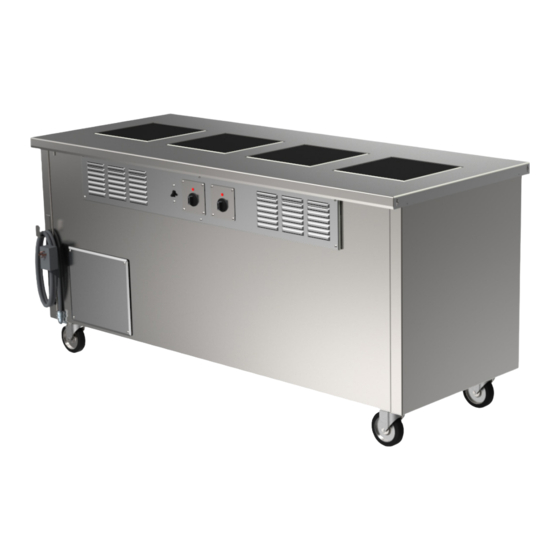
Summary of Contents for Welbilt Delfield EcoMark 1043 Series
- Page 1 Fresh Solutions, Fit For You Induction Unit Heat Retention Unit Installation, Operation and Maintenance Manual Caution Read this instruction before operating this equipment. Original Document Part Number: 9291543A 10/21...
- Page 2 Safety Notices Caution Maintenance and servicing work, other than cleaning as Warning described in this manual, must be done by an authorized Read this manual thoroughly before operating, installing service personnel. or performing maintenance on the equipment. Failure to follow instructions in this manual can cause property Notice damage, injury or death.
- Page 3 THIS PAGE INTENTIONALLY LEFT BLANK Part Number: 9291543 10/21...
-
Page 4: Table Of Contents
Table of Contents Section 1 General Information Model Numbers ........................5 Serial Number Location ..................... 5 Warranty Information ......................5 Regulatory Certifications ....................5 Section 2 Specifications General Specifications ....................... 6 Section 3 Installation Location ..........................8 Leveling ..........................9 Stabilizing ........................... -
Page 5: General Information
Section 1 General Information Model Numbers Serial Number Location Always have the serial number of your unit available This manual covers the following standard counters. when calling for parts or service. Serial numbers are Induction Units printed on serial tags. 1043A 1043B •... -
Page 6: Specifications
Section 2 Specifications Hot Holding Overview AIR INTAKE FILTER GENERATOR AIR INTAKE Cooktop Overview AIR FILTER S AIR DISCHARGE AIR INTAKE GENERATOR Part Number: 9291543A 10/21... -
Page 7: General Specifications
Section 2 Installation GENERAL SPECIFICATIONS CHART EcoMark 1043 Series Model Hobs / Sizes Wattage kW Current A Voltage 1043A (1) 12.6” x 12.6” 1043B (2) 12.6” x 12.6” 1043C (3) 12.6” x 12.6” 1.35 1043D (4) 12.6” x 12.6” 1043E (1) 20.47”... -
Page 8: Installation
Section 3 Installation The location selected for the equipment must meet the DANGER following criteria. If any of these criteria are not met, select Installation must comply with all applicable fire and another location. health codes in your jurisdiction. • Units are intended for indoor use only. -
Page 9: Leveling
Section 3 Installation Leveling Air Flow After the cabinet has been placed in the desired location, EcoMark Units cabinets with legs must be leveled. Level units from front to Units on castors or legs need a minimum of 20 inches back and from side to side. -
Page 10: Operation
Section 4 Operation Induction Unit Operation DANGER The on-site supervisor is responsible for ensuring that DANGER operators are made aware of the inherent dangers of operating this equipment. Steam can cause serious burns. Always use some type of protective covering on your hands and arms when DANGER removing lids from the unit. -
Page 11: Connections
Section 4 Operation Connections at generator – 1. Communications (A, B, C, D) 2. Control input for zone A & B 3. Control input for zone C & D 4. Power output for zone A 5. Power output for zone B 6. -
Page 12: Zone Combonations
Operation Section 4 Zone Combinations Control 1 – Controls zone A & B Control 2 – Controls zone C &D Note: Zone A is required for operation 140°F 140°F 140°F 180°F 140°F 140°F 140°F 180°F 140°F 180°F 180°F 140°F 140°F 180°F 180°F Part Number: 9291543A 10/21... -
Page 13: Errors
Section 4 Operation Temperature surveillance Errors If an error occurs, the display is used to show an error code. Heat sink temperature Example Error Display The temperature of the heat sink is detected by a temperature sensor. The temperature surveillance turns on an internal fan at 140°F to cool down the heat sink and stop at 131°F. -
Page 14: Maintenance
Section 5 Maintenance You are responsible for maintaining the equipment DANGER in accordance with the instructions in this manual. It is the responsibility of the equipment owner to Maintenance procedures are not covered by the warranty. perform a personal protective equipment hazard assessment to ensure adequate protection during maintenance procedures. -
Page 15: Exterior Cleaning
Section 5 Maintenance EXTERIOR CLEANING Tools and parts required • Scraper for stripping old silicone Warning • Degreaser or isopropyl alcohol When cleaning the unit, care should be taken to avoid • PACTAN 7076, 310ml the front power switch and the rear power cord. Keep water and/or cleaning solutions away from these parts. - Page 16 DELFIELD 980 SOUTH ISABELLA ROAD, MOUNT PLEASANT, MI 48858 800-733-8821 WWW.DELFIELD.COM ©2019 Welbilt Inc. except where explicitly stated otherwise. All rights reserved. Part Numbe: 9291543A 10/21...


Need help?
Do you have a question about the Delfield EcoMark 1043 Series and is the answer not in the manual?
Questions and answers