
Related Manuals for Raymarine AXIOM 2 PRO


Summary of Contents for Raymarine AXIOM 2 PRO
- Page 1 AXIOM 2 PRO MFD / CHARTPLOTTER INSTALLATION INSTRUCTIONS English (en-US) Date: 01-2023 Document number: 87443 (Rev 2) © 2023 Raymarine UK Limited...
- Page 3 Trademark and patents notice Raymarine, Tacktick, Clear Pulse, Truzoom, SeaTalk , SeaTalk , SeaTalkng , and Micronet, are registered or claimed trademarks of Raymarine Belgium. FLIR, YachtSense , DockSense, LightHouse, RangeFusion, DownVision, SideVision, RealVision, HyperVision, Dragonfly, Element, Quantum, Axiom, Instalert, Infrared Everywhere, The World’s Sixth Sense and ClearCruise are registered or claimed trademarks of FLIR Systems, Inc.
-
Page 5: Table Of Contents
......27 Publication copyright ............12 CHAPTER 5 PARTS SUPPLIED ..........28 CHAPTER 2 DOCUMENT INFORMATION ......13 Parts supplied - Axiom 2 Pro 9 / 12 ......29 Applicable products ............14 Parts supplied - Axiom 2 Pro 16 ........30 Document information .............14... - Page 6 CHAPTER 6 PRODUCT DIMENSIONS........31 Flush mounting ..............44 Axiom 2 Pro dimensions ..........32 Tools required (flush mount installations) ....44 Rear access requirements ...........44 CHAPTER 7 LOCATION REQUIREMENTS......33 Warnings and cautions Preparing the mounting surface — flush .............34 General location requirements ........34...
- Page 7 Miscellaneous troubleshooting 19.7 ......... 86 CHAPTER 14 VIDEO CONNECTIONS ........68 CHAPTER 20 TECHNICAL SUPPORT........88 Analog video connection 14.1 ..........69 Raymarine product support and servicing HDMI Out connection 20.1 ... 89 14.2 ........... 69 Viewing product information ........90 CHAPTER 15 AUDIO CONNECTIONS .........
- Page 8 CHAPTER 21 AXIOM 2 PRO 9 TECHNICAL Conformance/approvals 22.9 ..........100 SPECIFICATION ................. 92 Product markings 22.10 ............101 Power specification 21.1 ............93 CHAPTER 23 AXIOM 2 PRO 16 TECHNICAL Environmental specification 21.2 ........93 SPECIFICATION ............... 102 LCD specification 21.3 .............93...
- Page 9 APPENDIX A REPLACING THE NAME PLAQUE ....117 APPENDIX B REPLACING THE CARD READER DOOR ...................118 APPENDIX C NMEA 0183 SENTENCES.......119 APPENDIX D NMEA 2000 PGNS..........119...
-
Page 10: Chapter 1 Important Information
Warning: Marine-grade sealant • Raymarine highly recommends certified installation by Only use marine-grade neutral cure polyurethane sealants. a Raymarine approved installer. A certified installation Do NOT use sealants containing acetate or silicone, which can qualifies for enhanced product warranty benefits. -
Page 11: Rf Exposure
These limits are designed to provide reasonable protection against harmful interference in a residential installation. This equipment generates, uses, Raymarine does not warrant that this product is error-free or that it is and can radiate radio frequency energy and, if not installed and used in... -
Page 12: Warranty Registration
You will need this serial number when registering your product online. You should retain the label for future reference. Copyright ©2023 Raymarine UK Ltd. All rights reserved. No parts of this material may be copied, translated, or transmitted (in any medium) without the prior written permission of Raymarine UK Ltd. -
Page 13: Chapter 2 Document Information
CHAPTER 2: DOCUMENT INFORMATION CHAPTER CONTENTS • 2.1 Applicable products — page 14 • 2.2 Document information — page 14 • 2.3 Document conventions — page 14 • 2.4 Document illustrations — page 14 • 2.5 Product documentation — page 14 •... -
Page 14: Applicable Products
• Troubleshoot problems and obtain technical support if required. 2.4 Document illustrations This and other Raymarine® product documents are available to download in PDF format from www.raymarine.com/manuals Your product and if applicable, its user interface may differ slightly from that shown in the illustrations in this document, depending on product variant and date of manufacture. -
Page 15: User Manuals Print Shop
Please check the website to ensure you have the latest • 87317 — RCR-SD/USB card reader Installation Instructions documentation. • 87321 — Legacy MFD to Axiom Pro/Axiom 2 Pro adaptor plates installation instructions These and other Raymarine product documents are available to download... -
Page 16: Chapter 3 Product And System Overview
CHAPTER 3: PRODUCT AND SYSTEM OVERVIEW CHAPTER CONTENTS • 3.1 Product overview — page 17 • 3.2 Typical systems — page 18... -
Page 17: Product Overview
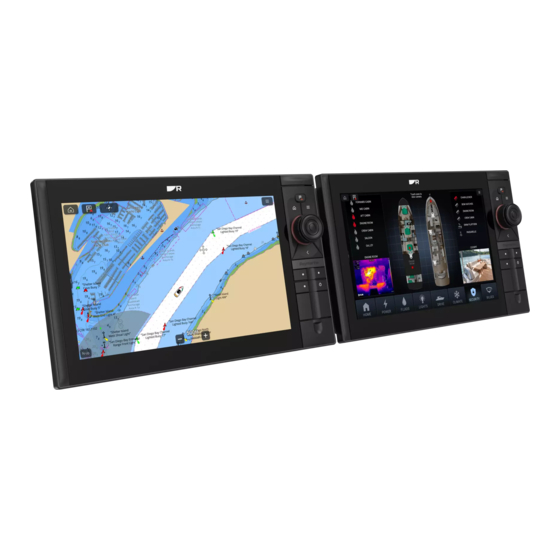
3.1 Product overview • NMEA 2000 DeviceNet connection (or SeaTalkng ®, via the supplied adapter cable). Axiom® 2 Pro is a range of HybridTouch ™ multifunction displays. • NMEA 0183 connection available, via optional NMEA 0183 to NMEA 2000 convertor (part number: A80721). •... -
Page 18: Typical Systems
5. External GNSS antenna (e.g.: GA200, part number A80589). 3. YachtSense ™ Digital Control System (Master module assembly illustrated). 6. Example Raymarine CHIRP sonar transducer, compatible with the Axiom 4. Raymarine radar scanner (Cyclone™ illustrated). 2 Pro S variant (CPT-S illustrated, connected via A80490 adaptor cable). - Page 19 8. SeaTalkng ® 5-way block (terminated SeaTalkng ® CAN bus network). 9. Example Raymarine RealVision™ Max sonar transducer, compatible with the Axiom 2 Pro RVM variant (RVM-100 illustrated). 10. Autopilot controller (P70s illustrated). 11. SeaTalkng ® 5-way block (terminated SeaTalkng ® CAN bus network).
-
Page 20: Chapter 4 Compatible Transducers
CHAPTER 4: COMPATIBLE TRANSDUCERS CHAPTER CONTENTS • 4.1 Axiom® 2 Pro RVM variant — compatible transducers — page 21 • 4.2 Axiom 2 Pro S variant - compatible transducers — page 26... -
Page 21: Axiom® 2 Pro Rvm Variant - Compatible Transducers
4.1 Axiom® 2 Pro RVM variant — compatible Transom mount transducers transducers Part number Transducer description A80703 RVM-100 RealVision™ Max 3D plastic transducer The following transducer types can be connected to the transducer connections on Axiom® 2 Pro RVM variant MFDs: Thru-hull mount transducers RV / RVM connection: Part number... -
Page 22: Sidevision™ Transducers
Part number Transducer description T70321: RV-320P / RV-320S RealVision™ 3D plastic 20° split-pair transducers A90473 A80474 A80615 RV-400 RealVision™ 3D stainless steel 0° transducer T70450: RV-412P / RV-412S RealVision™ 3D stainless steel 12° split-pair transducers A80616 A80617 T70451: RV-420P / RV-420S RealVision™ 3D stainless steel 20° split-pair transducers A80618 A80619... -
Page 23: Downvision™ Transducers
DownVision™ transducers Transom mount transducers DownVision™ transducers require an adapter cable (part number: A80490), Part number Transducer description and connect to the 25-pin RV/RVM transducer connector. E70342 CPT-S plastic transducer Thru-hull mount transducers Part number Transducer description E70339 CPT-S 0° Angled element plastic transducer A80448 CPT-S 12°... - Page 24 Part number Transducer description A80017 B75M 0° angled element bronze transducer A80018 B75H 0° angled element bronze transducer T70060 B75LH 0° angled element bronze split-pair transducers T70061 B75LM 0° angled element bronze split-pair transducers T70062 B75MH 0° angled element bronze split-pair transducers A80033 B75L 12°...
-
Page 25: Traditional Transducers
In-hull mount transducers Part number Transducer description Part number A80049 B175M 20° angled element bronze transducer Transducer description A80012 M265LH plastic transducer A80050 B175H 20° angled element bronze transducer T70075 B175LH 20° angled element bronze split-pair transducers A80038 M265LM plastic transducer T70076 B175LM 20°... -
Page 26: Axiom 2 Pro S Variant - Compatible Transducers
R199 plastic transducer A80569 SS60 12° angled element stainless steel transducer A80570 SS60 20° angled element stainless steel transducer 4.2 Axiom 2 Pro S variant - compatible A102137 B164 0° angled element bronze transducer transducers A102112 B164 12° angled element bronze transducer A102113 B164 20°... -
Page 27: Cpt-S Conical Beam Transducers
CPT-S conical beam transducers All transducer connections require the 25-pin to 9-pin transducer adapter cable accessory (part number: A80490) and connect to the transducer connector. CPT-S transducers do NOT offer DownVision™ capabilities. Transom mount transducers Part number Transducer description E70342 CPT-S plastic transducer Thru-hull mount transducers Part number... -
Page 28: Chapter 5 Parts Supplied
CHAPTER 5: PARTS SUPPLIED CHAPTER CONTENTS • 5.1 Parts supplied - Axiom 2 Pro 9 / 12 — page 29 • 5.2 Parts supplied - Axiom 2 Pro 16 — page 30... -
Page 29: Parts Supplied - Axiom 2 Pro 9 / 12
5.1 Parts supplied - Axiom 2 Pro 9 / 12 Item Description Mounting fixings x 4 (including M4 x 40 bolts, M4 plain washers, The following parts are supplied in the box. M4 nuts) Unpack your product carefully to prevent damage or loss of parts. Check the Documentation box contents against the list below. -
Page 30: Parts Supplied - Axiom 2 Pro 16
5.2 Parts supplied - Axiom 2 Pro 16 Item Description Documentation The following parts are supplied in the box. Power/video/audio cable, 1.5 m (4.92 ft) Unpack your product carefully to prevent damage or loss of parts. Check the box contents against the list below. Retain the packaging and documentation for future reference. -
Page 31: Chapter 6 Product Dimensions
CHAPTER 6: PRODUCT DIMENSIONS CHAPTER CONTENTS • 6.1 Axiom 2 Pro dimensions — page 32 Product dimensions... -
Page 32: Axiom 2 Pro Dimensions
6.1 Axiom 2 Pro dimensions Note: Trunnion bracket is included with the Axiom® 2 Pro 9 and Axiom® 2 Pro 12. For the Axiom® 2 Pro 16 the trunnion bracket is a separate accessory (part number: A80722). Axiom 2 Pro 9... -
Page 33: Chapter 7 Location Requirements
CHAPTER 7: LOCATION REQUIREMENTS CHAPTER CONTENTS • 7.1 Warnings and cautions — page 34 • 7.2 General location requirements — page 34 • 7.3 GNSS (GPS) location requirements — page 34 • 7.4 Touchscreen location requirements — page 36 • 7.5 Wireless location requirements for optimum performance —... -
Page 34: Warnings And Cautions
7.1 Warnings and cautions it in a protected area away from prolonged and direct exposure to rain and salt spray. Important: • Electrical interference — Select a location that is far enough away from Before proceeding, ensure that you have read and understood the devices that may cause interference, such as motors, generators and radio warnings and cautions provided in the following section of this document: transmitters / receivers. - Page 35 Prevailing conditions The weather and location of the vessel can affect performance. Typically calm clear conditions provide a more accurate position fix. Vessels at extreme northerly or southerly latitudes may also receive a weaker signal. An antenna mounted below decks will be more susceptible to performance issues related to the prevailing conditions.
-
Page 36: Touchscreen Location Requirements
7.4 Touchscreen location requirements Conductive materials in the signal path can have a significant impact on wireless signal performance. Reflective surfaces such as metal surfaces, some types of glass and even mirrors can drastically affect performance Note: or even block the wireless signal. Installation locations that are in close Touchscreen performance can be affected by the installation environment, proximity to these materials should be avoided. -
Page 37: Viewing Angle Considerations
Interference from other people’s wireless devices can cause interference with your products. You can use a third-party wireless analyzer tool / • Raymarine® equipment and cables connected to it are: smartphone app to assess the best wireless channel to use (e.g. a channel –... -
Page 38: Rf Interference
RF interference Certain third-party external electrical equipment can cause Radio Frequency (RF) interference with GNSS (GPS), AIS or VHF devices, if the external equipment is not adequately insulated and emits excessive levels of electromagnetic interference (EMI). Some common examples of such external equipment include LED lighting (e.g.: navigation lights, searchlights and floodlights, interior and exterior lights) and terrestrial TV tuners. -
Page 39: Chapter 8 Installation
CHAPTER 8: INSTALLATION CHAPTER CONTENTS • 8.1 Replacing the lower keypad — page 40 • 8.2 Mounting options — page 40 • 8.3 Trunnion mounting — Axiom® 2 Pro 9 and Axiom® 2 Pro 12 — page 41 • 8.4 Trunnion mounting — Axiom® 2 Pro 16 — page 42 •... -
Page 40: Replacing The Lower Keypad
5. Axiom 2 Pro 12 and Axiom 2 Pro 16 only — Insert one edge of the infill pilot control keypad with the user configurable lower keypad supplied with piece and then bend the infill piece slightly in the middle to allow the the display. -
Page 41: Trunnion Mounting - Axiom® 2 Pro 9 And Axiom® 2 Pro 12
Trunnion bracket mounting Note: Axiom® 2 Pro displays can be mounted on a trunnion bracket. Axiom® 2 Replacing a trunnion mounted or surface mounted Axiom® Pro display with Pro 9 and Axiom® 2 Pro 12 displays are supplied with a trunnion bracket. a new Axiom®... -
Page 42: Trunnion Mounting - Axiom® 2 Pro 16
3. Using the Trunnion bracket as a template, mark and drill the 5 x pilot 6. Small flat blade screwdriver (or plastic pry tool). holes on the mounting surface. 13 mm (1/2”) socket. 4. Secure the trunnion bracket to the mounting surface using your self tapping screws and an appropriate screwdriver. -
Page 43: Trunnion Bracket Mounting
1. Insert a small flat blade screwdriver or plastic pry tool into the center Ensure you have chosen a suitable mounting location for your display, which hole of the Trunnion bung. has sufficient headroom to allow the display’s angle to be adjusted, or the display to be removed if necessary. -
Page 44: Flush Mounting
6. The second person should secure the display to the trunnion bracket by 4. Half round file (or sandpaper). inserting and tightening the trunnion knobs, ensuring that the ratchet 5. Masking/self adhesive tape. teeth are correctly engaged. 6. Hand router with a router bit an appropriate size for the 11.50 mm (0.52 in) The knobs should be tightened by hand, sufficiently to prevent the corner diameter required for the flush mount rebate. -
Page 45: Flush Mounting
• 38.00 mm (1.5 in) — Axiom® 2 Pro 16. 5. Use a jigsaw or similar cutting tool to cut out the remainder of the cut out area. 6. Drill the 4 fixings holes at the marked location using a 3.7 mm ( ”) drill bit. -
Page 46: Surface Mounting
Note: The supplied gasket provides a seal between the display and a suitably flat and rigid mounting surface or binnacle. The gasket should be used in all installations. It may also be necessary to use a marine-grade sealant if the mounting surface or binnacle is not entirely flat and/or has a rough surface finish. -
Page 47: Rear Access Requirements
6. Marine grade sealant. Pozi-drive screwdriver. 8. 7 mm wrench or small adjustable wrench. 9. Drill bit 3.7 mm ( ”) for fixing holes. Rear access requirements Access to the rear of the display and mounting surface is required to surface and flush mount the display. -
Page 48: Surface Mounting
Surface mounting 4. Connect the relevant cables to the rear of the display. 5. Slide the display into the cut out area. Follow the steps below to surface mount the display. 6. Pull back the 3 corner bungs and open the card reader door. Important: 7. -
Page 49: Chapter 9 Cables And Connections - General Information
CHAPTER 9: CABLES AND CONNECTIONS — GENERAL INFORMATION CHAPTER CONTENTS • 9.1 General cabling guidance — page 50 • 9.2 Connections overview — RVM variant displays — page 51 • 9.3 Connections overview — S variant displays — page 51 •... -
Page 50: General Cabling Guidance
– High current carrying AC and DC power lines. • Unless otherwise stated only use cables supplied by Raymarine. – Antennas. • Where it is necessary to use non-Raymarine cables, ensure that they are of correct quality and gauge for their intended purpose. (e.g.: longer power Strain relief cable runs may require larger wire gauges to minimize voltage drop along the run). -
Page 51: Connections Overview - Rvm Variant Displays
9.2 Connections overview — RVM variant 8. Network — The 2 x network connectors enable connection of RayNet devices. displays 9. Ground — The optional grounding point should only be used when the display experiences touchscreen interference from nearby equipment. The following connections are available on Axiom®... -
Page 52: Connecting Cables
Unused bare ended wires Note: You can NOT connect RealVision™ Max 3D, RealVision™ 3D, DownVision™ or SideVision™ transducers to an S variant display. Any unused bare ended wires should be folded back and wrapped in insulation tape. 6. NMEA 2000 — The NMEA 2000 connector enables connection to a SeaTalkng ®... -
Page 53: Chapter 10 Power Connections
CHAPTER 10: POWER CONNECTIONS CHAPTER CONTENTS • 10.1 Power connection — page 54 • 10.2 Power distribution — page 54 • 10.3 Grounding — optional grounding point — page 57 Power connections... -
Page 54: Power Connection
• The suitable fuse rating for the thermal breaker is dependent on the number of devices you are connecting. If in doubt consult an authorized Raymarine dealer. • Your product’s power cable may have a fitted inline fuse. If not, you must fit an inline fuse to the positive wire of your product’s power connection. - Page 55 individual inline fuses for each power circuit to provide the necessary Important: protection. • When planning and wiring, take into consideration other products in • The power cable supplied with your product includes a drain wire, which your system, some of which (e.g. sonar modules) may place large power must be connected to the vessel’s common RF ground.
- Page 56 Implementation — direct connection to battery Suitable for a vessel with a common RF ground point. In this scenario, the power cable’s drain wire should be connected to the vessel’s common • Where connection to a power distribution panel is not possible, the power ground point.
-
Page 57: Grounding - Optional Grounding Point
10.3 Grounding — optional grounding point The dc power system should be either: • Negative grounded, with the negative battery terminal connected to the Frequencies emitted from equipment such as switch mode power supplies vessel's ground; or or MF/HF transmitters etc. can cause interference with your display’s touchscreen. -
Page 58: Chapter 11 Network Connections
CHAPTER 11: NETWORK CONNECTIONS CHAPTER CONTENTS • 11.1 NMEA 2000 / SeaTalkng connection — page 59 • 11.2 NMEA 0183 connection — page 59 • 11.3 Network connection — page 60... -
Page 59: Nmea 2000 / Seatalkng Connection
11.1 NMEA 2000 / SeaTalkng connection 11.2 NMEA 0183 connection The display can be connected to a NMEA 2000 / SeaTalkng ® network by The display can transmit and receive NMEA 0183 data when using a connecting a spur cable to the NMEA 2000 (DeviceNet) connector located compatible NMEA 2000 to NMEA 0183 converter, such as the Actisense®... -
Page 60: Network Connection
Example NMEA 0183 device connection using the Actisense® NGW-1 Connect to receiving device converter Converter signal (wire color) Receiving NMEA 0183 device signal TX/OUT A+ (White) RX/IN NOT CONNECTED TX/OUT B- (Blue) Shield/Screen Vessel Ground Connect to transmitting device Converter signal (wire color) Transmitting NMEA 0183 device signal RX/IN A+ (Red) -
Page 61: Cable Suppression Ferrites
2. RayNet to RayNet cable — Connect one end of the RayNet cable to your • Cable clips (not supplied) should be used to support the cable and ferrite. display, and the opposite end to a RayNet device or RayNet network •... -
Page 62: Chapter 12 Transducer Connections - Axiom 2 Pro Rvm
CHAPTER 12: TRANSDUCER CONNECTIONS - AXIOM 2 PRO RVM CHAPTER CONTENTS • 12.1 RealVision transducer connection — page 63 • 12.2 SideVision, DownVision and CPT-S transducer connection — page 64 • 12.3 CHIRP transducer connection — page 64 • 12.4 Traditional transducer connection — page 65... -
Page 63: Realvision Transducer Connection
For a list of compatible RealVision™ Max 3D transducers refer to: p.21 — RealVision™ Max 3D transducers Raymarine® offers he following optional extension cables are available: For a list of compatible RealVision™ 3D transducers refer to: • RealVision™ transducer extension cable 3 m (9.8 ft) (part number A80475) p.21 —... -
Page 64: Sidevision, Downvision And Cpt-S Transducer Connection
12.3 CHIRP transducer connection Split pair transducers: Extension cables fitted between the transducer and the ‘Y’ cable must be fitted in equal length pairs (i.e.: each transducer’s final cable length must be the same). CHIRP transducers can be connected directly to the display’s 11-pin 1kW Transducer connection. -
Page 65: Traditional Transducer Connection
Transducer connection using the 11-pin to 8-pin adaptor cable (part number: A80496). Display’s 1kW Transducer 11–pin connector. 2. 11-pin to 8-pin adaptor cable (part number: A80496). 3. Traditional transducer. For a list of compatible traditional transducers refer to: p.25 — Traditional transducers Transducer connections - Axiom 2 Pro RVM... -
Page 66: Chapter 13 Transducer Connections - Axiom 2 Pro S
CHAPTER 13: TRANSDUCER CONNECTIONS - AXIOM 2 PRO S CHAPTER CONTENTS • 13.1 CPT-S transducer connection — page 67... -
Page 67: Cpt-S Transducer Connection
Display’s Transducer 25-pin connector. 2. RV 25-pin to DV 9-pin adaptor cable (part number: A80490). 3. CPT-S transducer. For a list of compatible CPT-S transducers refer to: p.23 — CPT-S conical beam transducers Transducer connections - Axiom 2 Pro S... -
Page 68: Chapter 14 Video Connections
CHAPTER 14: VIDEO CONNECTIONS CHAPTER CONTENTS • 14.1 Analog video connection — page 69 • 14.2 HDMI Out connection — page 69... -
Page 69: Analog Video Connection
14.1 Analog video connection • 720 x 576p @ 50 Hz • 1280 x 720p @ 50 Hz / 60 Hz Analog video feeds from sources such as a Thermal camera or Security • 1920 x 1080p @ 50 Hz / 60 Hz camera can be connected to your display by connecting the device to the BNC connector on the display’s power/video/audio cable. -
Page 70: Chapter 15 Audio Connections
CHAPTER 15: AUDIO CONNECTIONS CHAPTER CONTENTS • 15.1 Audio (RCA) connections — page 71... -
Page 71: Audio (Rca) Connections
15.1 Audio (RCA) connections Note: Audio can also be output by connecting a Bluetooth speaker to the display. The display can output audio from installed 3rd party apps, such as Netflix For instructions on pairing a Bluetooth speaker refer to the operations and Spotify by connecting the RCA Audio connectors on the display’s instructions for your display (Document number: 81406). -
Page 72: Chapter 16 Usb Connections
CHAPTER 16: USB CONNECTIONS CHAPTER CONTENTS • 16.1 Accessory connection — page 73... -
Page 73: Accessory Connection
16.1 Accessory connection Axiom® 2 Pro displays include a built in dual slot MicroSD card reader. The Accessory connector can be used to expand storage capabilities by connecting an external memory card reader or external storage device to the display. ACCESSORY connector. -
Page 74: Chapter 17 Gps Antenna Connection
CHAPTER 17: GPS ANTENNA CONNECTION CHAPTER CONTENTS • 17.1 GNSS (GPS) antenna connection — page 75... -
Page 75: Gnss (Gps) Antenna Connection
17.1 GNSS (GPS) antenna connection For installations where the display does not have a clear view of the sky, or where a position fix is not possible or unreliable due to structure or other obstacles, a passive antenna (such as the GA200, part number A80589) can be connected to improve the performance of the display’s internal GNSS (GPS) receiver. -
Page 76: Chapter 18 Maintaining Your Display
CHAPTER 18: MAINTAINING YOUR DISPLAY CHAPTER CONTENTS • 18.1 Service and maintenance — page 77 • 18.2 Product cleaning — page 77... -
Page 77: Service And Maintenance
18.1 Service and maintenance 18.2 Product cleaning Best cleaning practices. This product contains no user serviceable components. Please refer all maintenance and repair to authorized Raymarine dealers. Unauthorized When cleaning products: repair may affect your warranty. • Switch off power supply. -
Page 78: Chapter 19 Troubleshooting
CHAPTER 19: TROUBLESHOOTING CHAPTER CONTENTS • 19.1 Troubleshooting — page 79 • 19.2 Power up troubleshooting — page 79 • 19.3 GNSS (GPS) troubleshooting — page 80 • 19.4 Sonar troubleshooting — page 81 • 19.5 Wi-Fi troubleshooting — page 83 •... -
Page 79: Troubleshooting
Blown fuse / tripped Check condition of relevant fuses and breakers Before packing and shipping, all Raymarine® products are subjected to breaker. and connections, replace if necessary. (Refer comprehensive testing and quality assurance programs. If you do experience... -
Page 80: Performing A Power On Reset On An Axiom® Pro Display
In the unlikely event that the product’s software No position fix has become corrupted, try downloading and Possible causes Possible solutions installing the latest software from the Raymarine website. Display installation Connect an external passive GNSS (GPS) antenna location (e.g.: such as the GA200 to the display GPS antenna 2. -
Page 81: Sonar Troubleshooting
• Check that the unit is correctly connected to connected to your external sonar module, which is correctly networked module: / RayNet the multifunction display or Raymarine network to your display. network problem. switch. If a crossover coupler or other coupler... - Page 82 No depth reading / lost bottom lock: Possible causes Possible solutions Possible causes Possible solutions Damaged cables Check the unit’s connector for broken or bent pins. Transducer location Check that the transducer has been installed in accordance with the instructions provided with the 2.
-
Page 83: Wi-Fi Troubleshooting
Possible causes Possible solutions Possible causes Possible solutions Sensitivity settings Check and adjust sensitivity settings or perform a Damaged or fouled Check the condition of the transducer ensuring it is may be inappropriate Sonar reset. transducer not damaged and is free from debris / fouling. for present Damaged transducer Check that the transducer cable and connection... - Page 84 Possible cause Possible solutions Possible cause Possible solutions Device not Try to enable broadcasting of the device’s Bulkheads, decks Try repositioning the devices so the structure is broadcasting. network using the Wi-Fi settings on the device and other heavy removed from the direct line of sight between you are trying to connect to.
- Page 85 Connection extremely slow and or keeps dropping out Possible cause Possible solutions Interference caused Temporarily switch off each device in turn until you Possible cause Possible solutions by other devices have identified the device causing the interference, Wi-Fi performance • Move devices closer together. that use the 2.4GHz then remove or reposition the offending device(s).
-
Page 86: Touchscreen Troubleshooting
Mobile application running slowly or not at all Possible cause Possible solutions 19.7 Miscellaneous troubleshooting Raymarine® app not Install mobile app from relevant app store. installed Miscellaneous problems and their possible causes and solutions are described here. - Page 87 • Check that the power source is of the correct voltage and sufficient current. Software mismatch Go to www.raymarine.com and click on support for on system (upgrade the latest software downloads. required). Corrupt data / other Perform a factory reset.
-
Page 88: Chapter 20 Technical Support
CHAPTER 20: TECHNICAL SUPPORT CHAPTER CONTENTS • 20.1 Raymarine product support and servicing — page 89 • 20.2 Learning resources — page 90... -
Page 89: Raymarine Product Support And Servicing
Raymarine offers dedicated service departments for warranty, service, and • E-Mail: support.it@raymarine.com repairs. • Tel: +39 02 9945 1001 Don’t forget to visit the Raymarine website to register your product for Spain (Authorized Raymarine distributor): extended warranty benefits: http://www.raymarine.co.uk/display/?id=788. • E-Mail: sat@azimut.es United Kingdom (UK), EMEA, and Asia Pacific: •... -
Page 90: Viewing Product Information
Use the [Settings] menu to view hardware and software information about To get started, you will first need to contact Raymarine Product Support. If the your display, and connected products. representative considers that your support case would benefit from a remote session, you need to first ensure that your display has an active Internet connection via Wi-Fi. - Page 91 Training courses Raymarine regularly runs a range of in-depth training courses to help you make the most of your products. Visit the Training section of the Raymarine website for more information: • http://www.raymarine.co.uk/view/?id=2372 Technical support forum You can use the Technical support forum to ask a technical question about a Raymarine product or to find out how other customers are using their Raymarine equipment.
-
Page 92: Chapter 21 Axiom 2 Pro 9 Technical Specification
CHAPTER 21: AXIOM 2 PRO 9 TECHNICAL SPECIFICATION CHAPTER CONTENTS • 21.1 Power specification — page 93 • 21.2 Environmental specification — page 93 • 21.3 LCD specification — page 93 • 21.4 Physical specification — page 93 • 21.5 Internal GNSS (GPS) receiver specification — page 94 •... -
Page 93: Power Specification
Internal storage: 64 GB solid state. Humidity: up to 93% @ 40°C (104°F) External storage: Dual slot MicroSDXC card reader IPx6 and IPx7 Water ingress protection: • Above decks Installation location: • Below decks Axiom 2 Pro 9 technical specification... -
Page 94: Internal Gnss (Gps) Receiver Specification
21.5 Internal GNSS (GPS) receiver specification 21.6 Connections specification Specification Specification Almanac Update: Automatic Accessory connection: USB Micro B (for external card reader connection). Antenna: Internal antenna, optional external antenna connection. Analog video connections: Composite BNC connectors via Power/Video/Audio cable. Channels: Track up to 28 satellites simultaneously. -
Page 95: Rvm Variant Sonar Specification
This product is compliant or approved to the following standards or by the listed entities. The following ranges apply to RealVision™ Max 3D sonar channels: • Radio Equipment Directive 2014/53/EU • EN 60945:2002 (Europe, Australia New Zealand) Axiom 2 Pro 9 technical specification... -
Page 96: Product Markings
• FCC Part 15C and Part 15E • ISED ICES-003 • NMEA 2000 certified 21.10 Product markings The product includes the following approval / compliance markings and/or IDs. • UKCA • CE • FCC • ISED • Japan • Australian Tick •... -
Page 97: Chapter 22 Axiom 2 Pro 12 Technical Specification
CHAPTER 22: AXIOM 2 PRO 12 TECHNICAL SPECIFICATION CHAPTER CONTENTS • 22.1 Power specification — page 98 • 22.2 Environmental specification — page 98 • 22.3 LCD specification — page 98 • 22.4 Physical specification — page 98 • 22.5 Connections specification — page 99 •... -
Page 98: Power Specification
22.1 Power specification 22.3 LCD specification Specification Specification Nominal supply voltage: 12 V / 24 V dc Size (diagonal): 12.1” Operating voltage range: 8 V dc to 32 V dc Type: IPS (In-Plane Switching) Current (Maximum): Color depth: 24-bit 11 mA (0.13 Watts) Off-current (Maximum @ 12 1280 x 800 (WXGA) Resolution:... -
Page 99: Connections Specification
• 165 dBm (Tracking) – 1x Antenna is used for Wi-Fi only • 160 dBm (Re-acquisition) – 1x Antenna is used for Bluetooth only • 148 dBm (Cold start) Refresh Rate: 10 Hz (10 times per second) Axiom 2 Pro 12 technical specification... -
Page 100: Rvm Variant Sonar Specification
Note: Specification • EGNOS The listed sonar channel ranges are indicative only, and are subject to SBAS compatibility: change depending upon the connected transducer. • GAGAN • MSAS Sonar channel Range • QZSS CHIRP sonar: 0.6 m (2 ft) to 366 m (1,200 ft) •... -
Page 101: Product Markings
• NMEA 2000 certified 22.10 Product markings The product includes the following approval / compliance markings and/or IDs. • UKCA • CE • FCC • ISED • Japan • Australian Tick • Brazil Anatel • WEEE Directive Axiom 2 Pro 12 technical specification... -
Page 102: Chapter 23 Axiom 2 Pro 16 Technical Specification
CHAPTER 23: AXIOM 2 PRO 16 TECHNICAL SPECIFICATION CHAPTER CONTENTS • 23.1 Power specification — page 103 • 23.2 Environmental specification — page 103 • 23.3 LCD specification — page 103 • 23.4 Physical specification — page 103 • 23.5 Connections specification — page 104 •... -
Page 103: Power Specification
Internal storage: 64 GB solid state. Humidity: up to 93% @ 40°C (104°F) External storage: Dual slot MicroSDXC card reader IPx6 and IPx7 Water ingress protection: • Above decks Installation location: • Below decks Axiom 2 Pro 16 technical specification... -
Page 104: Connections Specification
23.5 Connections specification Specification Transducer connections • 25-pin RV / RVM connector. Specification (RVM variants): • 11-pin 1kW connector. Accessory connection: USB Micro B (for external card reader Transducer connections (S 25-pin RV / RVM connector (requires connection). variants): adaptor cable for CPT-S only transducers. Analog video connections: Composite BNC connectors via Power/Video/Audio cable. -
Page 105: Rvm Variant Sonar Specification
The sonar range is the effective depth or distance that the transducer can • Radio Equipment Directive 2014/53/EU operate to, in optimum weather conditions. The following ranges apply to RealVision™ Max 3D sonar channels: • EN 60945:2002 (Europe, Australia New Zealand) Axiom 2 Pro 16 technical specification... -
Page 106: Product Markings
• FCC Part 15C and Part 15E • ISED ICES-003 • NMEA 2000 certified 23.10 Product markings The product includes the following approval / compliance markings and/or IDs. • UKCA • CE • FCC • ISED • Japan • Australian Tick •... -
Page 107: Chapter 24 Spares And Accessories
CHAPTER 24: SPARES AND ACCESSORIES CHAPTER CONTENTS • 24.1 Compatible transducers — page 108 • 24.2 Spares — page 108 • 24.3 Accessories — page 108 • 24.4 RayNet to RayNet cables and connectors — page 110 • 24.5 RayNet to RJ45, and RJ45 (SeaTalkhs) adapter cables — page 111 •... -
Page 108: Compatible Transducers
24.1 Compatible transducers 24.3 Accessories The following accessories are available for Axiom® 2 Pro displays. For a list of transducers that are compatible with your sonar module, refer to the following section: p.20 — Compatible transducers. Part number Description In addition, the following speed/temp sensing transducers are also Axiom®... -
Page 109: Legacy Adaptor Plates
Pro displays in the place of a legacy display. Part number Adaptor description C90W / E90W to Axiom Pro 9 / A80530 Axiom 2 Pro 9 adaptor plate C120W / E120W to Axiom Pro 12 / A80531 Axiom 2 Pro 12 adaptor plate A80533... -
Page 110: Raynet To Raynet Cables And Connectors
24.4 RayNet to RayNet cables and connectors Standard RayNet connection cable with a RayNet (female) socket on both ends. 2. Right-angle RayNet connection cable with a straight RayNet (female) socket on one end, and a right-angle RayNet (female) socket on the other end. Suitable for connecting at 90°... -
Page 111: Raynet To Rj45, And Rj45 (Seatalkhs) Adapter Cables
24.5 RayNet to RJ45, and RJ45 (SeaTalkhs) adapter cables Spares and accessories... - Page 112 Adapter cable with a RayNet (female) socket on one end, and a waterproof (female) RJ45 (SeaTalkhs ®) socket on the other end, accepting the following cables with an RJ45 (SeaTalkhs ®) waterproof locking (male) plug: • A62245 (1.5 m). • A62246 (15 m). 2.
-
Page 113: Seatalkng ® Cables And Accessories
24.6 SeaTalkng ® cables and accessories 2 x Backbone cables 5 m (16.4 ft) (part number: A06036). Used to create and extend the SeaTalkng backbone. SeaTalkng ® cables and accessories for use with compatible products. 1 x Backbone cable 20 m (65.6 ft) (part number: A06037). Used to create and extend the SeaTalkng backbone. - Page 114 1 x Power cable 2 m (6.6 ft) (part number: A06049). Used to provide 12 V dc power to the SeaTalkng backbone. 2. 1 x Spur cable 1 m (3.3 ft) (part number: A06039). Used to connect a device to the SeaTalkng backbone. 3.
- Page 115 • Spur cable 5 m (16.4 ft) (part number: A06041). 2. Elbow (right angled) to elbow (right angled) spur cable 0.4 m (1.3 ft) (part number: A06042). Used in confined spaces where a straight spur cable will not fit. 3. Elbow (right angled) to straight spur cable 1 m (3.3 ft) (part number: A06081).
- Page 116 SeaTalkng ® adaptors and adaptor cables 5. SeaTalkng to DeviceNet (male) adaptor cables. Connect NMEA 2000 devices that use a DeviceNet connector to the SeaTalkng backbone, or SeaTalkng adaptor cables are used to connect devices designed for different connect SeaTalkng devices to an NMEA 2000 network. The following CAN bus backbones (e.g.: SeaTalk or DeviceNet) to the SeaTalkng backbone.
-
Page 117: Appendix A Replacing The Name Plaque
7. Axiom 2 Pro 12 and Axiom 2 Pro 16 only — Insert one edge of the infill piece and then bend the infill piece slightly in the middle to allow the other edge to be inserted into the opposite side. -
Page 118: Appendix B Replacing The Card Reader Door
Refer to the Marabu website for ink details: https://www.marabu-inks.com/ • This information is provided for information only. Raymarine will not be held liable for the use of inappropriate ink or printing methods. 1. Open the Card reader door. -
Page 119: Appendix C Nmea 0183 Sentences
Operations manual LightHouse version Operations manual LightHouse 3 81360 LightHouse 3 81360 LightHouse 4 81406 LightHouse 4 81406 To obtain the latest version of the manual, visit: www.raymarine.com/manuals To obtain the latest version of the manual, visit: www.raymarine.com/manuals NMEA 0183 sentences... - Page 121 Index Analog video..................69 Audio ....................71 Bare wires .................... 52 Battery ....................56 Accessories ................... 108 Card reader..................73 Network adapter cables ..............111 CHIRPtransducers................64 Network cables................... 110 CPT-S transducers ................. 64, 67 RayNet cables..................110 DeviceNet .................... 59 SeaTalkng adaptor cables ..............
- Page 122 Documentation ..................14 Legacy adaptor..................15 Location requirements General ....................34 e-Label......................10 GNSS ....................34 Electromagnetic Compatibility..............37 GPS ...................... 34 EMC, See Electromagnetic Compatibility Touchscreen ..................36 Ethernet connection ................60 Viewing angle ..................37 External storage ..................73 Wireless ....................36 Wireless interference................
- Page 123 Sharing a breaker ................55 Suppression ferrite ...................61 Power connection ................... 54 Surface mounting ..................47 Power troubleshooting ................79 System examples ..................18 Product Dimensions ................32 Product documentation ................14 Product information .................90 Product overview..................17 Technical specification Product recycling (WEEE) .................12 Approvals................
- Page 126 Raymarine (UK / EU) Marine House, Cartwright Drive, Fareham, Hampshire. PO15 5RJ. United Kingdom. Tel: (+44) (0)1329 246 700 www.raymarine.co.uk Raymarine (US) 110 Lowell Road, Hudson, NH 03051. United States of America. Tel: (+1) 603-324-7900 www.raymarine.com...
Need help?
Do you have a question about the AXIOM 2 PRO and is the answer not in the manual?
Questions and answers