Raymarine AXIOM Advanced Operation Instructions
Hide thumbs
Also See for AXIOM:
- Basic operation instructions (60 pages) ,
- Installation instructions manual (114 pages) ,
- Advanced operation instructions (194 pages)

Related Manuals for Raymarine AXIOM


Summary of Contents for Raymarine AXIOM
- Page 1 Advanced operation instructions English (en-US) Date: 04-2017 Document number: 81370-1 © 2017 Raymarine UK Limited...
- Page 3 Software updates Check the Raymarine website for the latest software releases for your product. www.raymarine.com/software Product documentation The latest versions of all English and translated documents are available to download in PDF format from the website: www.raymarine.com/manuals.
-
Page 5: Table Of Contents
Contents Chapter 1 Important information..................11 Disclaimers ..........................11 Open source license agreements ................... 11 Warranty registration ......................... 11 Technical accuracy ........................11 Chapter 2 Document and product information............13 2.1 Product documentation...................... 14 Software revision ........................14 Chapter 3 Set up.......................15 3.1 Getting started........................ - Page 6 Demo profiles ........................29 4.5 My data ..........................31 Trip data..........................31 Files ............................32 Import/export ........................32 4.6 Settings..........................33 Selecting display language....................33 Boat details ...........................33 Units of measure........................34 Data master ..........................35 4.7 Man Overboard (MOB) ...................... 36 MOB mode..........................36 4.8 Alarms ..........................37 4.9 Satellite navigation / positioning ..................
- Page 7 Chart ranging and panning ....................61 Chart app context menu ....................... 61 Selecting a chart card ......................62 Chart modes ........................62 Vessel details........................63 Object selection and information..................63 Layers ...........................64 View and motion........................65 7.2 Navigation .......................... 66 Performing a Goto ....................... 66 Following a Route ........................
- Page 8 Bearing alignment........................ 96 9.5 Radar modes........................97 9.6 Range and bearing ......................98 VRM (Variable Range Marker) / EBL (Electronic Bearing Line)..........98 9.7 Target tracking......................... 100 Acquiring a target ....................... 100 Radar target symbols......................101 Target vectors and history ....................101 Dangerous targets alarm ....................
- Page 9 13.6 Camera troubleshooting ....................137 13.7 Data troubleshooting ......................139 13.8 Touchscreen troubleshooting ..................140 Chapter 14 Technical support..................141 14.1 Raymarine product support and servicing..............142 Viewing product information ....................143 14.2 Learning resources ......................144 Appendix A NMEA 2000 PGN support ...............145...
-
Page 11: Chapter 1 Important Information
Raymarine is not responsible for damages or injuries caused by your use or inability to use the product, by the interaction of the product with products manufactured by others, or by errors in chart data or information utilized by the product and supplied by third parties. -
Page 13: Chapter 2 Document And Product Information
Chapter 2: Document and product information Chapter contents • 2.1 Product documentation on page 14 Document and product information... -
Page 14: Product Documentation
2.1 Product documentation The following documentation is applicable to your product: All documents are available to download in PDF format from the Raymarine website www.raymarine.com. Description Part number LightHouse 3 Basic operation instructions 81369 LightHouse 3 Advanced operation instructions 81370... -
Page 15: Chapter 3 Set Up
Chapter 3: Set up Chapter contents • 3.1 Getting started on page 16 • 3.2 Inserting a MicroSD card on page 20 • 3.3 Shortcuts on page 21 • 3.4 Software updates on page 22 • 3.5 Device pairing on page 23 •... -
Page 16: Getting Started
3.1 Getting started First power up When you power up your new Multifunction Display (MFD) for the first time a number of actions are required. The list below shows the actions that should be performed on your new MFD: Power on the display. 2. -
Page 17: First Power Up Data Master Selection
Switching on and off at the breaker If you wish to ensure that the MFD is not consuming any power then it must be switched off at the breaker or have the power cable unplugged. When the breaker is switched back on, or the cable is reconnected, the MFD will resume in the same power state that it was in when it was switched off. -
Page 18: Data Sources
For MDS to be available all products in the system that use the data sources, must be MDS-compliant. The system will report any products that are NOT MDS-compliant. It may be possible to upgrade the software for these products, to make them compliant. Visit the Raymarine website (www.raymarine.com) to obtain the latest software for your products. -
Page 19: Identifying Engines
Identifying engines Engine data can be displayed on your MFD if your engines are transmitting the relevant supported data on to the MFD network. If your system has mislabelled your engines then you can correct this using the Engine identification wizard. The Engine identification wizard can be accessed from the Boat details tab: Homescreen >... -
Page 20: Inserting A Microsd Card
3.2 Inserting a MicroSD card 1. Pull back the microSD card reader cover as shown above. 2. Insert you microSD card with the contacts facing down. 3. Close the cover and ensure it is seated correctly. Removing a MicroSD card 1. -
Page 21: Shortcuts
3.3 Shortcuts The Shortcuts menu can be accessed by swiping left to right across the Power button swipe area. The following shortcuts are available: • Take Screenshot • Activate Touchlock • Stop Radar transmitting • Power off • Adjust Brightness Adjusting brightness LCD brightness can be adjusted from the Shortcuts menu. -
Page 22: Software Updates
Raymarine® regularly issues software updates for its products which provide new and enhanced features and improved performance and usability. You should ensure that you have the latest software for your products by regularly checking the Raymarine® website for new software releases. www.raymarine.com/software Note: •... -
Page 23: Device Pairing
3.5 Device pairing Pairing a RMK remote keypad You can control your MFD with an RMK external keypad. 1. Select Pair keypad from the This display tab of the Settings menu: Homescreen > Settings > This display > Pair keypad. 2. -
Page 24: Performing A Settings Or Factory Reset
3.6 Performing a settings or factory reset Performing a Factory reset will erase ALL user data and reset the MFD’s settings to Factory default values. Performing a Settings reset will restore your MFD’s settings to factory defaults, whilst retaining user data. 1. -
Page 25: Chapter 4 Homescreen
Chapter 4: Homescreen Chapter contents • 4.1 Accepting the Limitations on Use on page 26 • 4.2 Homescreen overview on page 27 • 4.3 Creating / Customizing an App page on page 28 • 4.4 User profiles on page 29 •... -
Page 26: Accepting The Limitations On Use
4.1 Accepting the Limitations on Use After your MFD has powered up the Homescreen is displayed. 1. Before using the MFD you must accept the Limitations on Use (LoU) disclaimer. To view the full LoU Disclaimer, select ‘more details’. The LoU acknowledgment is displayed each time the display is powered on and for each new user profile. -
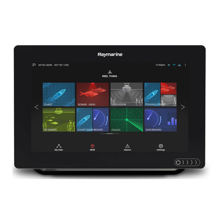
Page 27: Homescreen Overview
4.2 Homescreen overview All settings and apps can be accessed from the Homescreen. GNSS position/fix details — Select the area to view fix accuracy and access GNSS settings. 2. Profile — Select the area to change the profile in use or to create, edit or delete profiles. 3. -
Page 28: Creating / Customizing An App Page
4.3 Creating / Customizing an App page 1. Press and hold on an existing App page icon to display Popover options. You can Customize, Rename or Delete app pages from the Popover options. 2. Select Customize from the Popover options to change page layout and apps used. To Create a new page press and hold on a blank space on the Homescreen. -
Page 29: User Profiles
4.4 User profiles You can share your MFD with other users by creating user profiles on your MFD. Profiles enable you to retain your own personal settings whilst letting other users personalize the MFD’s settings to their preference. Note: User data such as Waypoints, Routes, Tracks, images and video recordings etc. will be available to all users. - Page 30 Selecting a Demo profile will provide your MFD with simulated data to help you practice operating your display. Important: • It is recommended that Demo profiles are NOT activated whilst navigating. • Demo profiles will NOT display any real data, including safety warnings and messages. •...
-
Page 31: My Data
4.5 My data Selecting the My data icon from the Homescreen provides access to user data such as Waypoints, Routes, Tracks, Trip data and media Files. You can also Import/export User data from the My data menu. Selecting Waypoints, Routes or Tracks will take you to the relevant list where you can manage and customize your data. -
Page 32: Files
Trip logs can be viewed by selecting Trip from the My Data page: Homescreen > My Data > Trip. The Trip logs available are: • Trip (manual) — accumulates data until reset. • Trip (day) — resets automatically when local time passes midnight. •... -
Page 33: Settings
4.6 Settings The Settings menu contains important information and settings for your MFD. The Settings menu is split up into different tabs, the settings available are: Options • View hardware and software information about your MFD. Getting started • View cartography details for inserted chart cards. •... -
Page 34: Units Of Measure
Option Description Enter your vessel’s maximum unladen height from the waterline. Min safe height: To ensure adequate clearance, it is recommended that you add a safety margin to this figure to allow for variation caused by vessel movements. Enter your vessel’s maximum width at its widest point. To Min safe width: ensure adequate clearance on both sides, it is recommended that you add a safety margin for port and starboard to this figure... -
Page 35: Data Master
Data master Systems containing more than one MFD must have a designated Data master MFD. The Data master is the primary MFD in the network, this should be the MFD that has the connection to the SeaTalkng ® / NMEA 2000 CAN bus network and any other devices and sources of data in your system. The Data master bridges the data over the SeaTalkhs ™... -
Page 36: Man Overboard (Mob)
4.7 Man Overboard (MOB) If a person or object falls overboard, you can use the Man Overboard (MOB) feature to mark the position that your vessel was at when the MOB alarm was activated. The MOB feature can be activated by pressing and holding on the MOB icon: on the Homescreen or the waypoint/MOB icon: found at the top of all apps. -
Page 37: Alarms
4.8 Alarms The Alarm manager can be accessed from the Homescreen. Example: Active alarms list Alarms are raised by system functions, and also external equipment connected to your display. When an Alarm is triggered all networked MFDs will display audible and visual warnings. The onscreen warning provides details of why the alarm has been triggered. -
Page 38: Satellite Navigation / Positioning
4.9 Satellite navigation / positioning GNSS Status Your vessel’s GNSS position is provided in the top left corner of the Homescreen. You can access fix accuracy and settings by selecting the area. If latitude and longitude is displayed on the Homescreen then you have a valid position fix. If the text turns red then your fix accuracy is low. - Page 39 • enable and disable your MFD’s internal GNSS receiver. Disable if you do not want to use this unit’s internal GNSS receiver as a source for positioning data. • restart the GNSS receiver that is being used as the source for your positioning data. Homescreen...
-
Page 40: External Devices
4.10 External devices You can view the status of peripheral devices connected to your MFD using the Status area, located at the top right of the Homescreen. You can also connect and disconnect from some devices using the Status area popover menu. Status area icons The following devices’... - Page 41 Icon Status Icon Status Sonar pinging Wi-Fi connected, signal strength High Sonar not pinging Wi-Fi connected, signal strength Medium Sonar error Wi-Fi connected, signal strength Touchlock active Wi-Fi not connected Wi-Fi error Homescreen...
-
Page 43: Chapter 5 General App Settings
Chapter 5: General app settings Chapter contents • 5.1 Sidebar on page 44 • 5.2 Data overlays on page 45 • 5.3 Editing the split ratio of a Splitscreen app page on page 46 • 5.4 App settings menus on page 47 General app settings... -
Page 44: Sidebar
5.1 Sidebar The Sidebar is available in all apps and provides quick access to system data. By default the Sidebar is set up to display navigation data. The Sidebar is displayed automatically in the Chart app when a Goto or follow is initiated. It can also be displayed at anytime by sliding your finger from left to right from the left edge of the screen. -
Page 45: Data Overlays
5.2 Data overlays System data can be overlaid onto the Chart app, Radar app, Sonar app and Camera app. Some apps have Data overlays enabled by default. Data overlays can be placed anywhere on the app page and can be placed over any app in a Splitscreen app page. -
Page 46: Editing The Split Ratio Of A Splitscreen App Page
5.3 Editing the split ratio of a Splitscreen app page With a Splitscreen app page displayed: 1. Select Edit split ratio from the Page settings tab: Menu > Settings > Page settings > Edit split ratio. 2. Drag the Resize icon to create the desired split ratio. 3. -
Page 47: App Settings Menus
5.4 App settings menus Each app includes a settings menu that provides access to app settings and features. The settings menu in each app is signified by the Settings icon. General app settings... -
Page 49: Chapter 6 Waypoints, Routes And Tracks
Chapter 6: Waypoints, Routes and Tracks Chapter contents • 6.1 Waypoints on page 50 • 6.2 Routes on page 53 • 6.3 Tracks on page 56 Waypoints, Routes and Tracks... -
Page 50: Waypoints
6.1 Waypoints Waypoints are used to mark specific locations or points of interest. Waypoints can be used in the Chart, Radar and Sonar apps. Your MFD can store up to 10,000 waypoints which can be sorted into up to 200 waypoint groups. In the Chart app you can navigate to a waypoint by selecting Goto from the Waypoint context menu. -
Page 51: Waypoint Management
1. Select and hold on the waypoint and select Goto from the context menu. 2. The Chart app will begin navigation, if required, physically engage your autopilot. 3. An alarm will sound when you reach the waypoint. Waypoint management Waypoints are managed using the Waypoint list. The Waypoint list can be accessed from the Homescreen and from the Chart app: Homescreen >... - Page 52 If the Waypoint list is accessed from the Chart app menu, the selected group or waypoint is displayed in a Chart pane on the right of the screen. You can Rename, Delete or Hide/Show the group by selecting the Group name at the top of the list. From the group list you can change the list sort order, Hide/Show the Waypoint group in the current Chart app instance or create a New waypoint.
-
Page 53: Routes
Routes are used to plan your journey in advance. You can plan your journey directly on your MFD, or at home using software capable of exporting Waypoints and Routes in standard .gpx format, such as Raymarine’s Voyage Planner software. Routes consist of a number of waypoints. Your MFD can store up to 250 Routes, each Route consisting of up to 500 waypoints. - Page 54 Route list From the route list you can Delete routes or create a New route using existing waypoints. To view a route plan, select a route and choose View route plan. Route plan The route plan displays a list of all waypoints in the route and when accessed from the Chart app also includes a Chart pane showing the route’s location.
- Page 55 Route options Rename route Give the route a name. Color Change the color the route appears in the Chart app. Switch the time between ETA (Estimated Time of Arrival) and Time TTG (Time To Go). Speed Switch the speed between Actual (SOG) and Planned. When the speed is set to Planned you can select a desired speed for navigating the route.
-
Page 56: Tracks
6.3 Tracks Tracks are used to record where you have been. Tracks are made up of track points that are created at regular time or distance intervals. You can store up to 15 tracks on your MFD, each track can contain up to 10,000 points. - Page 57 Track list From the track list you can Start or Stop tracks recording, Delete a track or choose how tracks are recorded. Track interval The track interval determines the time period or distance between track points when recording a track. You can choose whether to record track points by Time, by Distance or set to Auto. •...
-
Page 59: Chapter 7 Chart App
Chapter 7: Chart app Chapter contents • 7.1 Chart app overview on page 60 • 7.2 Navigation on page 66 • 7.3 Target tracking on page 67 • 7.4 Chart settings menu on page 71 Chart app... -
Page 60: Chart App Overview
7.1 Chart app overview The Chart app displays a representation of your vessel in relation to land masses and other charted objects, which enables you to plan and navigate to your desired destination. The Chart app requires a GNSS position fix in order to display your vessel at the correct location on a world map. For each instance of the Chart app you can select which electronic cartography that you want to use, the selection will persist over a power cycle. -
Page 61: Chart App Controls
Chart app controls Icon Description Action Home icon Takes you to the Homescreen Menu icon Opens the app menu Waypoint / MOB Place waypoint / hold down to activate Man overboard (MOB) alarm Find vessel Centers your vessel onscreen. Range In Decreases the range/distance displayed onscreen. -
Page 62: Selecting A Chart Card
Selecting a chart card You can use electronic charts from supported vendors to enhance the level of detail provided by the Chart app. The electronic chart card must be inserted into the MFD’s MicroSD card reader (or the card reader of an MFD on the same network). From the Chart app menu: 1. -
Page 63: Vessel Details
Vessel details The Vessel details popover provides access to vessel-related settings. From the Vessel details popover you can: • start/stop a track. • offset the position of the vessel symbol. • change the symbol used to represent your vessel. • set the length of vessel vectors. •... -
Page 64: Layers
Selecting and holding on the object will display the object context menu. From the context menu select: More options > Chart info and then select the object from the list to view its details. In areas where there is a high concentration of charted objects, selecting Nearby objects from the context menu will display a list of objects located nearby for you to choose from. -
Page 65: View And Motion
View and motion The view and motion tab allows you to control how the chart is displayed in relation to your vessel. Chart motion Chart motion controls how the chart and boat are drawn to keep the boat onscreen as you move. Chart orientation The orientation of the chart affects the alignment of the chart relative to your vessel, route or North. -
Page 66: Navigation
7.2 Navigation Performing a Goto You can perform a “Goto” to a Waypoint or specific location. 1. Select and hold on the Waypoint or point of interest on the Chart. 2. Select Goto from the context menu. You can stop the Goto at any time by selecting and holding anywhere in the Chart app and choosing Stop, or selecting another Goto. -
Page 67: Target Tracking
7.3 Target tracking With compatible AIS and Radar hardware connected to your MFD, you can track AIS and Radar targets. AIS targets can be tracked in the Chart app and Radar targets can be tracked in the Radar app and also in the Chart app, when the Radar layer is switched on. When targets are being tracked they appear in the AIS or Radar targets list. -
Page 68: Dangerous Targets Alarm
The vectors can be set to True or Relative. The Vector length identifies where the target will be after the specified time has passed. You can adjust the length of the vector by selecting a time from the Vector length popover options. AIS vectors can be set to All (displayed for all targets) or Manual (only displayed when turned on using the target’s context menu). -
Page 69: Radar Settings
To set up the Dangerous target alarm, first adjust the Safe distance to the desired value and then select a Time to reach safe distance. The alarm will be triggered if a tracked target will reach the specified Safe distance from your vessel within the time period selected. You can select whether you want the Dangerous target alarm to track Radar targets, AIS targets or both. - Page 70 Setting Description Options When enabled AIS target • On Hide static targets travelling under 2 knots will • Off be hidden, unless they are or become dangerous. When enabled your vessel’s • On Silent mode AIS will not transmit your •...
-
Page 71: Chart Settings Menu
7.4 Chart settings menu The table below lists settings applicable to the Chart app and their location within the app Settings menu. Cartography Settings Description Options Allows you to select the cartography that you Navionics List of available want to use in the current Chart app. LightHouse Charts cartography Layers tab... - Page 72 Settings Description Options Vendor Safe water from Determines the depth at which the Numeric value LightHouse Safety contour is displayed. (Vector) The Safety contour cannot be set less than the Shallow contour or greater than the Deep contour. Deep water from Allows you specify the depth at which Numeric value •...
- Page 73 Advanced tab Settings Description Options • North-up Chart orientation • Head-up • Course-up Enhanced AIS When the AIS layer is enabled, switches between • On targets using standard and enhanced AIS targets. • Off Enables use of Radar overlay without Heading •...
-
Page 75: Chapter 8 Sonar App
Chapter 8: Sonar app Chapter contents • 8.1 Sonar app overview on page 76 • 8.2 Opening the Sonar app on page 78 • 8.3 Sonar channels on page 81 • 8.4 Placing a Waypoint in the Sonar app on page 82 •... -
Page 76: Sonar App Overview
8.1 Sonar app overview The Sonar app displays a visualization of the echoes received from a Sonar module and transducer. The Sonar app is compatible with Traditional, CHIRP, DownVision™, SideVision™ and RealVision™ 3D sonar modules and transducers. The Sonar app builds an underwater view of bottom structure and targets in the water column. -
Page 77: Realvision 3D Controls
Icon Description Action When Auto range is enabled, pressing the plus icon activates Range/Zoom In Zoom mode, subsequent presses will increase the Zoom factor. When Range is set to Manual pressing the Plus icon decreases the distance displayed onscreen. Auto range can be enabled and disabled from the Menu: Menu >... -
Page 78: Opening The Sonar App
The Sonar app is opened by selecting a page icon from the Homescreen that includes a Sonar app. Pre-requisites: Ensure your Sonar module is compatible (check the latest details available on the Raymarine website). If in doubt please contact an authorized Raymarine dealer for advice. - Page 79 No sonar source available If the ’No sonar source available’ warning is displayed then either: • your sonar module is still powering up. • your MFD cannot establish a connection with your external Sonar module • your Internal Sonar module has no transducer connected. Check your external sonar module’s network and power connection, check your MFD’s network or transducer connection ensuring the connections and cabling is correct and free from damage, then power cycle your system.
- Page 80 Check your transducer connection(s) are correct and free from damage, then power cycle your system. If the transducer is still not found then refer to your equipment’s installation documentation for further troubleshooting information.
-
Page 81: Sonar Channels
8.3 Sonar channels The Sonar channels that are available depend on the Sonar module and transducer you have connected. RealVision™ 3D SideVision™ DownVision™ High CHIRP / High Frequency Medium CHIRP / Medium Low CHIRP / Low Frequency Frequency Selecting a Sonar channel The first time you open a new Sonar app page you will be requested to select a channel, subsequently you can change the sonar channel by selecting a channel icon from the Sonar app menu. -
Page 82: Placing A Waypoint In The Sonar App
8.4 Placing a Waypoint in the Sonar app When you observe something of interest in the Sonar app you can place a waypoint at its location so that you can find the area again. 1. Select and hold on the point of interest onscreen. The Context menu is displayed and scrolling is paused, temporarily. -
Page 83: Sonar Sensitivity Controls
8.5 Sonar sensitivity controls Optimum performance is usually achieved using the default settings. You can adjust the image using the Sensitivity controls to improve the displayed image. Sensitivity settings can be accessed using the onscreen Image adjustment icon, or the Adjust sensitivity menu option: Menu >... -
Page 84: Sonar Settings Menu
8.6 Sonar settings menu The table below lists settings applicable to the Sonar app and their location within the app Settings menu. The settings available are dependant upon the Sonar module in use. Sonar display tab Settings Description Options Color palette Various color palettes are available to suit List of color palettes. - Page 85 Settings Description Options Bottom colors Changes the color used for bottom structure. List of colors. Background Changes the color used for the app background. List of colors. Transducer tab Settings Description Options Transducer Allows selection of Sonar transducer. List of available transducers.
- Page 86 Settings Description Options Interference Removes interference caused by other • Auto rejection transducers on your vessel or from vessels • Low equipped with transducers close by. • Medium • High • Off 2nd echo rejection The control helps to remove false target returns •...
-
Page 87: Chapter 9 Radar Application
Chapter 9: Radar application Chapter contents • 9.1 Radar app overview on page 88 • 9.2 Radar feature comparison on page 90 • 9.3 Opening the Radar app on page 93 • 9.4 Set up on page 95 • 9.5 Radar modes on page 97 •... -
Page 88: Radar App Overview
9.1 Radar app overview The Radar app displays a visualization of the echoes received from a connected Radar scanner. The Radar app is an aid used to help enhance collision and situational awareness by enabling target’s distance and speed to be tracked in relation to your vessel. Up to 2 Radar scanners can be connected at the same time. -
Page 89: Radar App Context Menu
Icon Description Action Range In Decreases the distance displayed onscreen (minimum range: 1/16nm). Range Out Increases the distance displayed onscreen (up to your Radar scanner’s maximum range). Radar app context menu Context menus provide context sensitive menu options. • Context menus are accessed in the Radar app by selecting a location or target. -
Page 90: Radar Feature Comparison
9.2 Radar feature comparison The range of features and settings that are available in the Radar app is dependent on the type of connected Radar scanner. Sensitivity controls Features/settings Radar type Gain • All Color Gain • Quantum™ • SuperHD™ Open Array •... - Page 91 Features/settings Radar type Radar Targets • Quantum™ = 10 • SuperHD™ Open Array = 25 • HD Open Array = 25 • HD Radome = 25 • Digital Radome = 10 Tuning • SuperHD™ Open Array • HD Open Array •...
-
Page 92: Compatible Radar Scanners
Compatible Radar scanners The table below lists Radar scanners that can be used with the Radar app. • Quantum™. • SuperHD™ Open Array. • HD Open Array. • HD Radome. • Digital Radome. -
Page 93: Opening The Radar App
The Radar app is opened by selecting a page icon from the Homescreen that includes the Radar app. Pre-requisites: Ensure your Radar scanner is compatible, check the latest details available on the Raymarine website, if in doubt please contact an authorized Raymarine dealer for advice. -
Page 94: Putting The Radar Into Standby
Standby (Not transmitting) If the ‘Standby’ message is displayed then select Transmit to begin transmitting. Transmitting If your Radar scanner is connected, powered up and transmitting then the Radar image is displayed and echoes/targets are displayed onscreen. Putting the Radar into Standby With your selected Radar displayed onscreen: 1. -
Page 95: Set Up
9.4 Set up Selecting a Radar scanner On systems with 2 Radar scanners, you can select which Radar scanner is used in each instance of the Radar app. 1. Select the Settings icon from the Radar app menu. 2. Select the Scanner: box on the Transmission tab. A list of available Radar scanners is displayed. -
Page 96: Timed Radar Transmission
Dual range limitations: • Dual range cannot be enabled when Radar targets are being tracked (clear the target list and try again). • When Dual range is enabled Radar target tracking is disabled. • When Dual range is enabled Automatic Radar target acquisition is disabled. •... -
Page 97: Radar Modes
9.5 Radar modes The Radar app provides preset modes that can be used to quickly achieve the best picture depending on your current situation. Only Radar modes supported by your Radar scanner are shown. To change Radar mode select the required mode from the Radar app menu. HARBOR Harbor mode takes into account land clutter that is typically encountered in a Harbor, so that smaller targets are still visible. -
Page 98: Range And Bearing
9.6 Range and bearing The Radar app helps you identify a target’s range (distance) and bearing from your vessel. SHM (Ships heading marker). 2. COG/SOG line (Points in the direction of travel (COG), with the length of the vector providing an indication of speed (SOG)). - Page 99 Centered VRM/EBLYou can use a ‘Centered’ (on your vessel) VRM/EBL to determine the range and bearing of targets in relation to your vessel. 2. Floating VRM/EBLYou can use a ‘Floating’ VRM/EBL to determine the range and bearing between 2 targets. Editing a VRM-EBL Once a VRM/EBL has been placed you can adjust its size and position.
-
Page 100: Target Tracking
9.7 Target tracking The Radar app can be used to acquire and track targets. When a target is being tracked it will be displayed in the Radar target list. The target lists can be accessed by selecting Targets from the app menu: Menu > Targets . Selecting a target from the list will highlight the selected target in the app pane on the right of the screen. -
Page 101: Radar Target Symbols
Radar target symbols Symbol Status Description Acquiring target — Manual Thin dashed Green circle Acquiring target — Auto Thick dashed Red circle, flashes until acknowledged Auto-acquired target — Red circle, flashes until acknowledged Unacknowledged Acquired target Green circle with Target ID Dangerous target Red circle with Target ID, flashes until acknowledged... - Page 102 Target vectors The vectors can be set to True or Relative. The Vector length identifies where the target will be after the specified time has passed. You can adjust the length of the vector by selecting a time from the Vector length popover options. Additional CPA and target information can be displayed for each target using the context menu (select a target to display the context menu).
-
Page 103: Dangerous Targets Alarm
Dangerous targets alarm You can use the Dangerous targets alarm to notify you if a target will reach a specified distance from your vessel within a specified time. To set up the Dangerous target alarm, first adjust the Safe distance to the desired value and then select a Time to reach safe distance. - Page 104 A Guard zone can be configured as a sector or as a circle around your vessel. Selecting Adjust Zone allows you to configure the size of the Guard Zone. Adjust the guard zone size by dragging the inner and outer perimeter end points (circles) to the desired locations.
-
Page 105: Radar Sensitivity Controls
9.8 Radar sensitivity controls Optimum performance is usually achieved using the default settings. You can adjust the image using the Sensitivity controls to improve the displayed image. Sensitivity settings can be accessed using the onscreen Image adjustment icon, or the Adjust sensitivity menu option: Menu >... -
Page 106: Radar Settings
9.9 Radar settings The Settings menu provides access to the Radar app’s features and functions. The options available in the Settings menu are dependent on the type of Radar scanner connected. Transmission tab Settings Description Options Scanner Allows you to select the Radar scanner that you List of available Radar want to use. - Page 107 Settings Description Options screen, the image is redrawn to reveal the area ahead. In True motion mode the boat position is fixed to Full offset. The boat position determines the position of • Center Boat position your vessel onscreen. You can adjust the Boat •...
- Page 108 Installation tab Under normal circumstances it should not be necessary to adjust Installation settings. Settings Description Options Bearing alignment Enables you to align the Radar image correctly • 179.5° Port to 180° in relation to your vessel’s bow. Starboard Parking offset Allows you to select the ‘parked position of your •...
-
Page 109: Chapter 10 Dashboard App
Chapter 10: Dashboard app Chapter contents • 10.1 Dashboard app overview on page 110 • 10.2 Dashboard settings menu on page 112 Dashboard app... -
Page 110: Dashboard App Overview
10.1 Dashboard app overview The Dashboard app enables you to view system data. System data may be generated by your MFD or by devices connected to your MFD via SeaTalkng ® / NMEA 2000 and SeaTalkhs ™. The Dashboard app can also be configured to provide control of your compatible Digital Switching devices. Note: For data to be available in the Dashboard app it must be being transmitted to your MFD from compatible hardware using supported protocols and messages. -
Page 111: Customizing Existing Data Pages
Customizing existing Data pages The data items displayed on each page can be changed. 1. Select and hold on the relevant Data item. 2. Select Edit from the Data item popover menu. 3. Select the new Data item that you want to display. Alternatively you can select Customize page from the app menu: Menu >... -
Page 112: Dashboard Settings Menu
• Reset all Import custom You can import custom pages that have been Displays file browser pages created using approved PC based page creation software. Please refer to Raymarine Product support for more details. Circuits tab Settings Description Options • Acknowledged... - Page 113 Settings Description Options Determines how bearing and heading data is • True Bearing mode displayed. • Magnetic System Datum Determines the datum used by your MFD. List of available datums. This should be set to the same datum used by your paper charts.
-
Page 115: Chapter 11 Camera App
Chapter 11: Camera app Chapter contents • 11.1 Camera app overview on page 116 • 11.2 Opening the Camera app on page 117 • 11.3 Camera settings on page 119 Camera app... -
Page 116: Camera App Overview
11.1 Camera app overview IP (Internet protocol) video feeds can be viewed, recorded and played back using the Camera app. Examples of IP video feeds include: IP CCTV camera and IP Thermal imaging camera. It may be possible to view analog video feeds when using a suitable Analog to IP video converter. Up to 4 IP video feeds can be displayed simultaneously when using a splitscreen app page. -
Page 117: Opening The Camera App
The Camera app is opened by selecting an app page from the Homescreen that includes the Camera app. Pre-requisites: Ensure your camera is compatible by checking the latest details available on the Raymarine website against your IP camera’s specification. If in doubt please contact an authorized Raymarine dealer for advice. -
Page 118: Selecting An Ip Video Feed
• a Camera app page is opened for the first time and no compatible camera is connected. • a Camera app page is opened for the first time before the camera has finished booting up. If the ‘No camera detected’ message is displayed for more than 2 minutes, then your MFD cannot connect to your camera. -
Page 119: Camera Settings
11.3 Camera settings The Settings menu provides access to the Camera app’s features and functions. The options available in the Settings menu are dependent on your system configuration and connected Cameras. Cycling tab Settings Description Options Cycle Delay Determines the time each camera will be •... - Page 120 Photo & Video recording tab Settings Description Options Determines the save location for photos and • SD 1 Save files to: video recordings. • External SD 1 USB Media Note: External SD 1 and USB Media are available when using the RCR-SDUSB Accessory.
-
Page 121: Chapter 12 Audio Application
Chapter 12: Audio application Chapter contents • 12.1 Audio app overview on page 122 • 12.2 Opening the Audio app on page 124 • 12.3 Getting started on page 126 • 12.4 Audio app menu options on page 128 Audio application... -
Page 122: Audio App Overview
12.1 Audio app overview The Audio app can be used to control a compatible NMEA 2000 entertainment system that is connected to the same SeaTalkng ® network. The Audio app can be displayed in Fullscreen and half screen portrait app pages. If more than 1 compatible Entertainment system is present on the network then the first system to obtain a network connection will be controlled by the Audio app. - Page 123 Icon Description Function Volume Up Increases volume for current zone. Forwards • Skip to the next track (USB and Bluetooth) • Seek/Search Forward (Radio) Backwards • Skip back to beginning of current track (USB and Bluetooth) • Seek/Search Backward (Radio) Manual Tune •...
-
Page 124: Opening The Audio App
Ensure your Entertainment system is compatible by checking the latest details available on the Raymarine website. If in doubt please contact an authorized Raymarine dealer for advice. 2. Ensure you have installed your Entertainment system in accordance with the documentation that was supplied with the system. - Page 125 No audio devices found If the ‘No audio device found’ message is displayed for more than 10 seconds, then your MFD cannot connect to your Entertainment system. Ensure network and power connections to your Entertainment system and MFD are correct and free from damage and then power cycle your system.
-
Page 126: Getting Started
12.3 Getting started Selecting an audio source 1. Select the audio source you want to listen to from the app Menu. Before you can select an audio source from your MFD, the source must already be available to your Entertainment system’s main control unit (“head unit”). Muting and unmuting 1. -
Page 127: Saving Presets
Saving presets Up to 4 presets can be saved for each Radio audio source (i.e.: AM Radio, FM Radio, Weather, SiriusXM and Pandora). 1. Whilst listening to the station you want to save, press and hold the relevant Preset button for approximately 3 seconds. -
Page 128: Audio App Menu Options
12.4 Audio app menu options Menu item Description Options Tracks Enables you to browse for tracks on • Folder USB/Bluetooth devices connected to your • Play Queue Entertainment system Channels Provides a list of available SiriusXM Channel list channels Stations Provides a list of available Pandora stations Station list Enables you to select an audio source... -
Page 129: Chapter 13 Troubleshooting
Chapter 13: Troubleshooting Chapter contents • 13.1 Troubleshooting on page 130 • 13.2 Power up troubleshooting on page 131 • 13.3 Radar troubleshooting on page 132 • 13.4 GNSS troubleshooting on page 133 • 13.5 Sonar troubleshooting on page 134 •... -
Page 130: Troubleshooting
If after referring to this section you are still having problems with your product, please refer to the Technical support section of this manual for useful links and Raymarine Product Support contact details. -
Page 131: Power Up Troubleshooting
Software corruption In the unlikely event that the products software has become corrupted please try re-flashing the latest software from the Raymarine website. 2. On display products, as a last resort, you can try to perform a ‘Power on Reset’, however this will delete all settings/presets and user data (such as waypoints and tracks) and revert the unit back to factory defaults. -
Page 132: Radar Troubleshooting
Open Array • Ensure Open Array power switch is in the On position. power in Off position Software • Ensure all Raymarine products contain the latest available software, check the mismatch Raymarine website: www.raymarine.com/software for software compatibility. between... -
Page 133: Gnss Troubleshooting
13.4 GNSS troubleshooting No fix displayed Possible causes Possible solutions Geographic location or prevailing conditions Check to see if a fix is obtained in better preventing satellite fix. conditions or another geographic location. GNSS connection fault. Ensure that external GNSS connections and cabling are correct and fault free. -
Page 134: Sonar Troubleshooting
Check all connections ensuring connections are secure, problem. clean and free from corrosion, replace if necessary. External sonar module: Ensure all Raymarine products contain the latest available software, Software mismatch between check the Raymarine website: www.raymarine.com/software equipment may prevent software compatibility. - Page 135 Possible causes Possible solutions Damaged cables Check the unit’s connector for broken or bent pins. 2. Check that the cable connector is fully inserted into the unit and that the locking collar is in the locked position. 3. Check the cable and connectors for signs of damage or corrosion, replace if necessary.
- Page 136 Possible causes Possible solutions Transducer location • Check that the transducer has been installed in accordance with the instructions provided with the transducer. • If a transom mount transducer is mounted too high on the transom it may be lifting out of the water, check that the transducer face is fully submerged when planing and turning.
-
Page 137: Camera Troubleshooting
13.6 Camera troubleshooting Video not displayed Possible causes Possible solutions Incorrect power up sequence Your MFD needs to be powered up before your camera to enable the MFD to provide the camera with a valid IP address. Camera not compatible. Ensure the camera feed and network settings are compatible: •... - Page 138 Noisy image Possible causes Possible solutions Poor quality or faulty cabling. • Ensure cable runs are no longer than they need to be. • Use only high quality shielded cable suitable for the marine environment. • Ensure you are using a high quality shielded cable. Cable is picking up electromagnetic interference •...
-
Page 139: Data Troubleshooting
• Check power to the data bus. Software mismatch between equipment may • Check the Raymarine website and ensure prevent communication. all your Raymarine products have the latest software. Instrument or other system data is missing from some but not all displays... -
Page 140: Touchscreen Troubleshooting
13.8 Touchscreen troubleshooting Touchscreen does not operate as expected. Possible causes Possible solutions Touch lock is enabled. Disable TouchLock, using the power button.. Screen is not being operated with bare fingers, Bare fingers must make contact with the screen for example gloves are being worn. for correct operation. -
Page 141: Chapter 14 Technical Support
Chapter 14: Technical support Chapter contents • 14.1 Raymarine product support and servicing on page 142 • 14.2 Learning resources on page 144 Technical support... -
Page 142: Raymarine Product Support And Servicing
You can obtain this product information using the menus within your product. Servicing and warranty Raymarine offers dedicated service departments for warranty, service, and repairs. Don’t forget to visit the Raymarine website to register your product for extended warranty benefits: http://www.raymarine.co.uk/display/?id=788. Telephone... -
Page 143: Viewing Product Information
Denmark +45 437 164 64 support.dk@raymarine.com (Raymarine subsidiary) Russia +7 495 788 info@mikstmarine.ru 0508 (Authorized Raymarine distributor) Viewing product information The Getting started tab contains hardware and software information for your MFD. 1. Select Settings, from the Homescreen. Technical support... -
Page 144: Learning Resources
14.2 Learning resources Raymarine has produced a range of learning resources to help you get the most out of your products. Video tutorials Raymarine official channel on YouTube: • http://www.youtube.com/user/RaymarineInc Video Gallery: • http://www.raymarine.co.uk/view/?id=2679 Product Support videos: • http://www.raymarine.co.uk/view/?id=4952 Note: •... -
Page 145: Appendix A Nmea 2000 Pgn Support
Appendix A NMEA 2000 PGN support Description Transmit Receive • • 59392 ISO Acknowledgment • • 59904 ISO Request • • 60928 ISO Address Claim • • 126208 NMEA - Request group function • • 126464 Receive/Transmit PGN's group function •... - Page 146 130577 Direction Data • • • 130578 Vessel Speed Components Raymarine® provides field programmability of the Device and System Instances within PGN 60928 which can be commanded via use of PGN 126208 as required by the latest NMEA 2000 standard.
- Page 149 Index GNSS ...............38 GNSS (GPS) Settings ..........38 GNSS/GPS troubleshooting........133 Goto Enhanced targets..........69 waypoint ..............66 silent mode ............70 GPS................38 Alarm manager ............37 Alarms ..............37 App pages Creating ...............28 Customizing ............28 Homescreen ............27 Backup ..............32 Import/export............31 Battery selection............34 Initial setup ..............
- Page 150 follow ..............66 Routes ..............53 Variation ..............113 capacity..............53 Routes list ..............31 Warranty ..............142 Waypoint ..............50 Safe depth, minimum..........34 capacity............... 50 Safe height, minimum ..........34 Waypoint list .............31 Safe width, minimum ..........34 SBAS ...............38 Screenshot .............. 21 Selection..............35 Service Center............
- Page 152 Raymarine Marine House, Cartwright Drive, Fareham, Hampshire. PO15 5RJ. United Kingdom. Tel: +44 (0)1329 246 700 www.raymarine.com a brand by...
Need help?
Do you have a question about the AXIOM and is the answer not in the manual?
Questions and answers
How is the autopilot engaged?
@Gordon Adam From my dashbaord on a switch.
Silent mode in Targets-AIS settings is appears and disappears. I am unable to turn silent mode on due to this
the light is yellow and the display on my Axiom 9 are black. What is wrong?