
Related Manuals for Teledyne Forge 5GigE


Summary of Contents for Teledyne Forge 5GigE
- Page 1 INSTALLATION GUIDE FORGE® Version 1.0 Revised 1/18/2023 1/18/2023 ©2015-2023 FLIR Integrated Imaging Solutions Inc. All rights reserved.
- Page 2 Hardware Warranty The warranty for the Forge 5GigE camera is 3 years. For detailed information on how to repair or replace your camera, please see the terms and conditions on our website.
-
Page 3: Table Of Contents
3.2 Installing your Interface Card and Software 3.3 Installing your Forge 5GigE 3.4 Powering your Forge 5GigE 4 Tools to Control your Forge 5GigE 4.1 Using the Spinnaker® SDK 4.1.1 SpinView Camera Evaluation Application 4.1.2 Custom Applications Built with the Spinnaker API 4.2 Using GenICam Applications... - Page 4 6.7 Mounting your Forge 5GigE 6.8 Camera Temperature and Heat Dissipation 6.9 Lens Mounting 6.9.1 Back Flange Distance 6.10 Non-Volatile Flash Memory 6.11 Dust Protection 6.12 Infrared Cut-Off Filters 6.13 Readout Method 6.13.1 Global Shutter 7 Input/Output Control 7.1 General Purpose Input/Output (GPIO) 7.2 GPIO Electrical Characteristics...
-
Page 5: Forge 5Gige Installation Guide
1 Forge 5GigE Installation Guide Forge 5GigE Installation Guide Welcome to the Forge 5GigE camera. We offer a number of resources to assist you with the Forge 5GigE. Spinnaker SDK—software development kit that provides GenICam-compliant controls to create applications for the camera. -
Page 6: Handling Precautions And Camera Care
Terms and Conditions on our website. Your Teledyne FLIR machine vision camera is a precisely manufactured device and should be handled with care. Here are some tips on how to care for the device. Avoid electrostatic charging. When handling the camera unit, avoid touching the lenses. Fingerprints will affect the quality of the image produced by the device. -
Page 7: Forge 5Gige Installation
5GigE) Interface card (see Interface Card) Teledyne FLIR sells a number of the additional parts required for installation. To purchase, visit the Accessories page. Have you visited the Teledyne FLIR website? A downloads account is required to download software and firmware. -
Page 8: Installing Your Interface Card And Software
3 Forge 5GigE Installation Installing your Interface Card and Software 1. Install your Interface Card Ensure the card is installed per the manufacturer's instructions. Connect the internal IDE or SATA power connector on the card to the computer power supply. Alternatively, use your PC's built-in host controller, if equipped. -
Page 9: Installing Your Forge 5Gige
3 Forge 5GigE Installation 3. Optimize the settings of your Ethernet card a. In Start->All Programs-> Spinnaker SDK->SpinView, right click on the Network Adapter and select Adapter Configuration. The Adapter Config Utility lists your network adapters and allows you to access the following:... - Page 10 3 Forge 5GigE Installation If both power sources are connected the camera always uses external power over the GPIO connector. The camera does not transmit images for the first 100 ms after power-up. The auto-exposure and auto-white balance algorithms do not run while the camera is powered down. It may therefore take several images to get a satisfactory image.
-
Page 11: Tools To Control Your Forge 5Gige
4 Tools to Control your Forge 5GigE Tools to Control your Forge 5GigE The Forge 5GigE's features can be accessed using various controls, including: Spinnaker SDK including API examples SpinView camera evaluation application, included in the Spinnaker SDK installation Third-party GenICam applications ®... -
Page 12: Using Genicam Applications
4 Tools to Control your Forge 5GigE Using GenICam Applications GigE Vision is an interface standard that allows for fast image transfer over Ethernet networks. All cameras supporting GigE Vision interact the same way with software also supporting GigE Vision. -
Page 13: Configuring Forge 5Gige Setup
GenICam Features Transport Layer Control. Alternatively, SpinView is a tool included with the Spinnaker SDK that allows you to set the internet protocol (IP) configuration for any GigE interface cards or Teledyne FLIR GigE Vision cameras connected to your system. Using SpinView, you can: Set the IP address for the current connection. -
Page 14: Allocating Bandwidth
5 Configuring Forge 5GigE Setup Dynamic (DHCP)—The camera is set to automatically obtain an IP address. This means that the IP address may change (within a range) every time the camera or computer is restarted. It may take up to one minute for the IP address to resolve and the camera to enumerate. -
Page 15: Configuring Other Ethernet Settings
5 Configuring Forge 5GigE Setup If using the first method, each camera has the full bandwidth allocation available to it. If using the second method, the combination of all cameras on a switch cannot exceed the available bandwidth. Related Knowledge Base Articles Setting Up Multiple GigE Cameras... -
Page 16: Forge 5Gige Firmware
Firmware is programming that is inserted into the programmable read-only memory (programmable ROM) of most Teledyne FLIR cameras. Firmware is created and tested like software. When ready, it can be distributed like other software and installed in the programmable read-only memory by the user. - Page 17 5 Configuring Forge 5GigE Setup Related Knowledge Base Articles Teledyne FLIR machine vision software and firmware version numbering systems Determining my camera's firmware version Should I upgrade my camera firmware or software? 1/18/2023 ® Teledyne FLIR Forge Installation Guide ©2015-2023 FLIR Integrated Imaging...
-
Page 18: Forge 5Gige Physical Interface
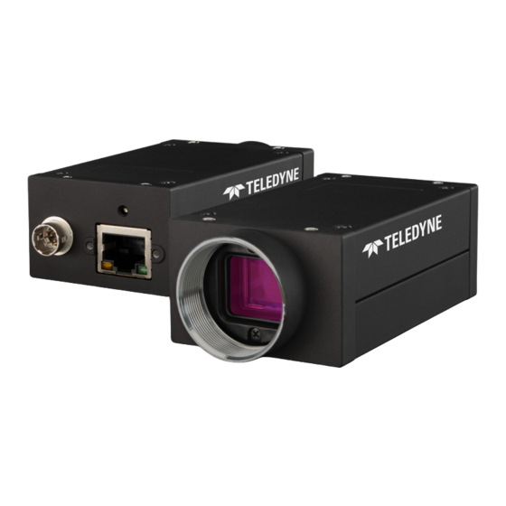
6 Forge 5GigE Physical Interface Forge 5GigE Physical Interface Forge 5GigE Physical Description 1. Glass/IR filter system 5. M3X0.5 mounting holes (x4) Dust Protection Infrared Cut-Off Filters See Mounting your Forge 5GigE 2. Lens holder 6. General purpose I/O connector Lens Mounting General Purpose Input/Output (GPIO) 3. -
Page 19: Forge 5Gige Dimensions
6 Forge 5GigE Physical Interface Forge 5GigE Dimensions Download 3D CAD Models / Drawings: CAD Models Forge 5GigE Dimensional Drawing Barrel Length "A" Models (+0.1/-0.3) FG-5PG-50S4 1/18/2023 ® Teledyne FLIR Forge Installation Guide ©2015-2023 FLIR Integrated Imaging Solutions Inc. All rights reserved. -
Page 20: Interface Connector
Category 5e cables up to 40 meters in length can be used with 5GigE. For cable lengths greater than 40 meters, Category 6a cables should be used. Teledyne FLIR sells Category 5e cables. Note: For optimal ESD protection, we recommend using a shielded Ethernet cable or connecting the camera housing to chassis ground (earth). -
Page 21: General Purpose Input/Output (Gpio)
9014 Bytes. How to Optimize GigE Network Adapter Settings for more information on configuring for best performance. To purchase a compatible card from Teledyne FLIR, visit the Products Accessories page. Note: For optimal video streaming and camera control performance, we recommend an Intel Pro chipset on a PCIe interface. -
Page 22: Mounting Your Forge 5Gige
6 Forge 5GigE Physical Interface Mounting your Forge 5GigE Using the Case The case is equipped with: Two (2) M3x0.5 mounting holes on the top of the case Four (4) M3x0.5 mounting holes on the bottom of the case Forge Mounting Top... -
Page 23: Camera Temperature And Heat Dissipation
Make sure the camera has enough open space around it to facilitate the free flow of air. To access temperature information query the GenICam Device Control feature DeviceTemperature. Lens Mounting Lenses are not included with cameras. Teledyne FLIR sells a number of lenses compatible with our cameras from website. There is also a Lens Calculator to help choose an appropriate lens. -
Page 24: Dust Protection
6 Forge 5GigE Physical Interface 6.11 Dust Protection The camera housing is designed to prevent dust from falling directly onto the sensor's protective glass surface. This is achieved by placing a piece of clear glass (monochrome camera models) or an IR cut-off filter (color models) that sits above the surface of the sensor's glass. - Page 25 6 Forge 5GigE Physical Interface Transmission Wavelength T=50% 680 nm ±10 nm T>80% 400 nm - 420 nm T>85% 420 nm - 650 nm T average 1% 750 nm - 1100 nm T<3% 750 nm - 1100 nm The following are the properties of the IR filter glass:...
-
Page 26: 6.13 Readout Method
6 Forge 5GigE Physical Interface 6.13 Readout Method 6.13.1 Global Shutter For cameras with a global shutter sensor, for each frame all of the lines start and stop exposure at the same time. The exposure time for each line is the same. Following exposure, data readout begins. The readout time for each line is the same but the start and end times are staggered. -
Page 27: Input/Output Control
The camera is equipped with a 6-pin GPIO connector on the back of the case. The connector is a Hirose HR10A-7R-6PB, the mating connector is a Hirose HR10A-7P-6S(73). 1/18/2023 ® Teledyne FLIR Forge Installation Guide ©2015-2023 FLIR Integrated Imaging Solutions Inc. All rights reserved. - Page 28 1—GPIO cable assembly wire colors 2—Dual function pin 3—Open drain output, requires pullup resistor 4—Output low level depends on the output voltage / pullup resistor combination 1/18/2023 ® Teledyne FLIR Forge Installation Guide ©2015-2023 FLIR Integrated Imaging Solutions Inc. All rights reserved.
-
Page 29: Gpio Electrical Characteristics
11.93 V 5.4 mA 12 V 2.4 KΩ 0.98 V 11.93 V 4.5 mA 24 V 4.7 KΩ 0.75 V 23.75 V 4.9 mA 1/18/2023 ® Teledyne FLIR Forge Installation Guide ©2015-2023 FLIR Integrated Imaging Solutions Inc. All rights reserved. - Page 30 7 Input/Output Control Note: Parts designators in the schematics shown below are for reference only. Opto-isolated input/output circuit Non-isolated input/output circuit 1/18/2023 ® Teledyne FLIR Forge Installation Guide ©2015-2023 FLIR Integrated Imaging Solutions Inc. All rights reserved.
-
Page 31: Input Timing Characteristics
Output Rise Time 5.77 µS Output Fall Time 2.99 µS Propagation Delay (High to Low) tPDHL 4.01 µS Propagation Delay (Low to High) tPDLH 25.29 µS 1/18/2023 ® Teledyne FLIR Forge Installation Guide ©2015-2023 FLIR Integrated Imaging Solutions Inc. All rights reserved. - Page 32 Propagation delay was measured at middle of rising and falling edges of the pulses Camera’s top case temperature during measurements was ~55°C Values are for reference only. They could vary depending on the test conditions. 1/18/2023 ® Teledyne FLIR Forge Installation Guide ©2015-2023 FLIR Integrated Imaging Solutions Inc. All rights reserved.
-
Page 33: Output Timing Characteristics
Propagation delay measured at middle of rising and falling edges of the pulses Camera’s top case temperature during measurements was ~55°C Values are for reference only. They could vary depending on the test conditions 1/18/2023 ® Teledyne FLIR Forge Installation Guide ©2015-2023 FLIR Integrated Imaging Solutions Inc. All rights reserved. - Page 34 Measured Pulse Frequency from FPGA = 65.52 Hz Measured Pulse Width from FPGA = 500.1 uS Values are for reference only. They could vary depending on the test conditions. 1/18/2023 ® Teledyne FLIR Forge Installation Guide ©2015-2023 FLIR Integrated Imaging Solutions Inc. All rights reserved.
-
Page 35: Troubleshooting
8 Troubleshooting Troubleshooting Support Teledyne FLIR endeavors to provide the highest level of technical support possible to you. Most support resources can be accessed through your product's Support page. Forge Support Articles Forge Resources The Overview tab contains links to: Spinnaker SDK download... -
Page 36: Status Indicator Led
DHCP IP Address Blinking Green (3 blinks) Persistent IP Address Solid Green Acquisition Started Rapid Flashing Green Firmware update in progress Flashing Green and Red General Error 1/18/2023 ® Teledyne FLIR Forge Installation Guide ©2015-2023 FLIR Integrated Imaging Solutions Inc. All rights reserved. -
Page 37: Contacting Us
For any questions, concerns or comments please contact us via the following methods: Email General questions Support Ticket Technical support Find specifications, support articles, downloads on the Website product page at Teledyne FLIR machine vision Revision History Version Date Description January 18, 2023 Support for FG-P5G-50S4 1/18/2023 ®...
Need help?
Do you have a question about the Forge 5GigE and is the answer not in the manual?
Questions and answers