Table of Contents
Advertisement
Quick Links
LIST OF FIGURES ............................................................................................................. 1
LIST OF TABLES ............................................................................................................... 1
1.
INTRODUCTION ......................................................................................................... 1
2.
BOARD ASSEMBLY ................................................................................................... 1
3.
QUICK START ............................................................................................................ 3
4.
FUNCTIONAL DESCRIPTION .................................................................................... 4
5.
HARDWARE SCHEMATIC ......................................................................................... 5
6.
ADC161S626 EVALUATION BOARD BILL OF MATERIALS ................................... 6
EVALUATION BOARD/KIT/MODULE (EVM).................................................................. 11
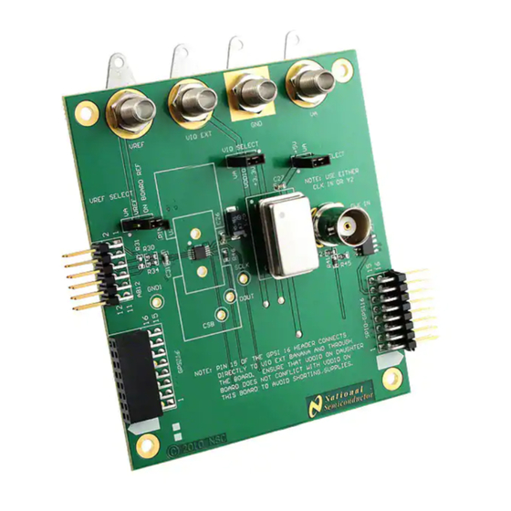
Figure 1: ADC161S626 Eval board connected to SPIO board. ..................................... 3
Table 1: Test Points on the ADC161S626 Evaluation Board ........................................ 2
Table 2: Connectors on the ADC161S626 Evaluation Board ....................................... 2
Table 3: Jumpers .............................................................................................................. 2
1.
Introduction
The ADC161S626BEB Evaluation Board Design Kit (consisting of the ADC161S626BEB board, this users
guide, an optional SPIO4 board and an optional sensor board) is intended to ease evaluation of the
ADC161S626. With the optional SPIO4 board and optional Sensor board, the board allows evaluation of an
entire Sensor AFE system.
The evaluation board can be used in stand alone mode, in which the user interfaces with the part through the
SPIO-GPSI16 connector and applies input signals on the AB12 connector. The board can also be used with
an SPIO4 board in place of an external pattern generator. Finally, in the Sensor AFE system, the
ADC161S626BEB board and the optional sensor board (for example, the LMP91000 Configurable AFE Gas
Sensor board) can be used with an SPIO4 board to evaluate the entire Sensor AFE system.
2.
Board Assembly
The ADC161S626BEB evaluation board comes fully assembled and ready for use. Refer to the Bill of
Materials for a description of components and to the schematic at the end of this document. There are
jumper selections for choosing between different power supply and clock configurations.
SNAU120-April 2012
ADC161S626BEB User's Guide
LIST OF FIGURES
LIST OF TABLES
User's Guide
SNAU120-April 2012
ADC161S626BEB User's Guide
1
Advertisement
Table of Contents

Related Manuals for Texas Instruments ADC161S626BEB


Summary of Contents for Texas Instruments ADC161S626BEB
-
Page 1: Table Of Contents
Sensor board) can be used with an SPIO4 board to evaluate the entire Sensor AFE system. Board Assembly The ADC161S626BEB evaluation board comes fully assembled and ready for use. Refer to the Bill of Materials for a description of components and to the schematic at the end of this document. There are jumper selections for choosing between different power supply and clock configurations. -
Page 2: Board Assembly
Va, 3.3V from the SPIO connector or the VIO EXT banana jack. VA SELECT Allows choice of VA for the part. Choices are VA banana jack or 5V from the SPIO connector. Table 3: Jumpers ADC161S626BEB User’s Guide SNAU120-April 2012... -
Page 3: Quick Start
Ensure that a 4MHz crystal is installed in the socket Y2 and that there is no signal applied at the CLK IN BNC jack. • Connect the SPIO4 board to the ADC161S626BEB board at the SPIO-GSPI16 male header. Line up the white arrows on the bottom of the headers. •... -
Page 4: Functional Description
These signals can be provided by the SPIO4 or SPUSI2 board. In stand alone mode, these signals must be provided by the user on the SPIO-GPSI16 header. The signal levels are TTL and CMOS compatible. The voltage expected is set by the value of VDDIO that is applied to the board. ADC161S626BEB User’s Guide SNAU120-April 2012... -
Page 5: Hardware Schematic
Hardware Schematic SNAU120-April 2012 ADC161S626BEB User’s Guide... -
Page 6: Adc161S626 Evaluation Board Bill Of Materials
RES, 20.0 ohm, 1%, 0.1W, 0603 Vishay-Dale CRCW060320R0F RES, 27.4 ohm, 1%, 0.1W, 0603 Vishay-Dale CRCW060327R4F R41, R45 RES, 51.1 ohm, 1%, 0.1W, 0603 Vishay-Dale CRCW060351R1F GND, VA, Standard Banana Jack, Johnson 108-0740-001 VIO EXT, Uninsulated, 15A Components VREF ADC161S626BEB User’s Guide SNAU120-April 2012... - Page 7 EVALUATION BOARD/KIT/MODULE (EVM) ADDITIONAL TERMS Texas Instruments (TI) provides the enclosed Evaluation Board/Kit/Module (EVM) under the following conditions: The user assumes all responsibility and liability for proper and safe handling of the goods. Further, the user indemnifies TI from all claims arising from the handling or use of the goods.
- Page 8 Concerning EVMs including detachable antennas Under Industry Canada regulations, this radio transmitter may only operate using an antenna of a type and maximum (or lesser) gain approved for the transmitter by Industry Canada. To reduce potential radio interference to ADC161S626BEB User’s Guide SNAU120-April 2012...
- Page 9 Also, please do not transfer this product, unless you give the same notice above to the transferee. Please note that if you could not follow the instructions above, you will be subject to penalties of Radio Law of Japan. Texas Instruments Japan Limited SNAU120-April 2012 ADC161S626BEB User’s Guide...
- Page 10 (address) 24-1, Nishi-Shinjuku 6 chome, Shinjukku-ku, Tokyo, Japan http://www.tij.co.jp 【ご使用にあたっての注意】 本開発キットは技術基準適合証明を受けておりません。 本製品のご使用に際しては、電波法遵守のため、以下のいずれかの措置を取っていただく必要がありますのでご注 意ください。 (1)電波法施行規則第6条第1項第1号に基づく平成18年3月28日総務省告示第173号で定められた電波暗 室等の試験設備でご使用いただく。 (2)実験局の免許を取得後ご使用いただく。 (3)技術基準適合証明を取得後ご使用いただく。 なお、本製品は、上記の「ご使用にあたっての注意」を譲渡先、移転先に通知しない限り、譲渡、移転できないも のとします。 上記を遵守頂けない場合は、電波法の罰則が適用される可能性があることをご留意ください。 日本テキサス・インスツルメンツ株式会社 東京都新宿区西新宿6丁目24番1号 西新宿三井ビル http://www.tij.co.jp ADC161S626BEB User’s Guide SNAU120-April 2012...
-
Page 11: Evaluation Board/Kit/Module (Evm)
FDA Class III or similar classification, then you must specifically notify TI of such intent and enter into a separate Assurance and Indemnity Agreement. SNAU120-April 2012 ADC161S626BEB User’s Guide... - Page 12 TI products are designated by TI as compliant with ISO/TS 16949 requirements. Buyers acknowledge and agree that, if they use any non-designated products in automotive applications, TI will not be responsible for any failure to meet such requirements. Following are URLs where you can obtain information on other Texas Instruments products and application solutions: Products...
- Page 13 Mailing Address: Texas Instruments, Post Office Box 655303, Dallas, Texas 75265 Copyright © 2007, Texas Instruments Incorporated SNAU120-April 2012 ADC161S626BEB User’s Guide...
Need help?
Do you have a question about the ADC161S626BEB and is the answer not in the manual?
Questions and answers