Table of Contents
Advertisement
Quick Links
See also:
Operator's Manual
Table of Contents
Predelivery Instructions
Read the Pre-Delivery and Operator manuals entirely. When you see this sym-
!
bol, the subsequent instructions and warnings are serious - follow without ex-
ception. Your life and the lives of others depend on it!
Cover illustration may show optional equipment not supplied with standard unit.
ORIGINAL INSTRUCTIONS
© Copyright 2018
Table of Contents
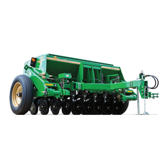
706NT/1006NT
End-Wheel No-Till Drill
Manufacturing, Inc.
www.greatplainsmfg.com
Printed 01/22/2018
21718
EN
150-285Q
Advertisement
Chapters
Table of Contents

Related Manuals for GREAT PLAINS 706NT


Summary of Contents for GREAT PLAINS 706NT
- Page 1 Table of Contents Predelivery Instructions 706NT/1006NT End-Wheel No-Till Drill Manufacturing, Inc. www.greatplainsmfg.com Read the Pre-Delivery and Operator manuals entirely. When you see this sym- bol, the subsequent instructions and warnings are serious - follow without ex- ception. Your life and the lives of others depend on it! 21718 Cover illustration may show optional equipment not supplied with standard unit.
- Page 2 Table of Contents Table of Contents...
-
Page 3: Table Of Contents
Great Plains Manufacturing, Inc. assumes no responsibility for errors or omissions. Neither is any liability assumed for damages resulting from the use of the information contained herein. Great Plains Manufacturing, Inc. reserves the right to revise and improve its products as it sees fit. - Page 4 Table of Contents Table of Contents...
-
Page 5: Important Safety Information
706/1006NT Table of Contents Important Safety Information Important Safety Information Look for Safety Symbol The SAFETY ALERT SYMBOL indicates there is a potential hazard to personal safety involved and extra safety precaution must be taken. When you see this symbol, be alert and carefully read the message that follows it. - Page 6 706/1006NT Table of Contents Important Safety Information Wear Protective Equipment Wear protective clothing and equipment. Wear clothing and equipment appropriate for the job. Avoid loose-fitting clothing. Because prolonged exposure to loud noise can cause hearing impairment or hearing loss, wear suitable hearing protection such as earmuffs or earplugs.
- Page 7 706/1006NT Table of Contents Important Safety Information Keep Riders Off Machinery Riders obstruct the operator’s view. Riders could be struck by foreign objects or thrown from the machine. Never allow children to operate equipment. Keep all bystanders away from machine during operation. Use Safety Lights and Devices Slow-moving tractors and towed implements can create a hazard when driven on public roads.
- Page 8 706/1006NT Table of Contents Important Safety Information Shutdown and Storage Lower drill, put tractor in park, turn off engine, and remove the key. Secure drill using blocks and supports provided. Detach and store drill in an area where children normally do not play.Use A Safety Chain ...
-
Page 9: Safety Decals
Keep all safety decals clean and legible. Replace all damaged or missing decals. Order new decals from your Great Plains dealer. Refer to this section for proper decal placement. When ordering new parts or components, also request corresponding safety decals.To install new decals:... -
Page 10: Introduction
Introduction Introduction Great Plains Manufacturing wants you to be satisfied with any new machine delivered by the Great Plains Trucking network. To ease the assembly task and produce a properly working machine, read this entire manual before setting up new equipment. -
Page 11: Using This Manual
For additional help with understanding these assembly instructions or for any other assembly or setup related questions, please contact our service department at the following address: Great Plains Service Department 1525 E. North St. P.O. Box 5060 Salina, KS 67402-5060 Or call us at (800) 270-9302 to speak over the phone with a service representative. -
Page 12: Setup
706/1006NT Table of Contents Preparation Preparation Step-by-step instructions for assembling the drill begin in the next section of the manual. Before commencing work, review the Tools Required and Pre-Assembly Checklist to make sure you have all necessary parts and equipment. The drill is shipped via flat bed truck. -
Page 13: Refer To Figure 2
706/1006NT Table of Contents Unloading Truck Unloading Truck See page 11 for hoisting tongue. Hoist drill from above. Do not fork-lift from beneath drill. There are no suitable lift points. Do not hoist via lugs after tongue is installed. Drill is not balanced at lugs with tongue installed. Refer to Figure 2 1. -
Page 14: Refer To Figure 3
706/1006NT Table of Contents Assembly Assembly Pre-Assembly Checklist 1. Read understand “Important Safety Information” before assembling. 2. Have at least two people on hand while assembling. 3. Make sure the assembly area is level and free of obstructions (preferably an open concrete area). 4. -
Page 15: Prepare Folding Tongue
706/1006NT Table of Contents Assembly Prepare Folding Tongue If tongue is already unfolded, continue at “Install Tongue” below. Refer to Figure 4 4. Locate two sets: (22) 802-615C HHCS 1-8X2 3/4 GR. 5 (29) 804-027C WASHER LOCK SPRING 1 PLT (24) 803-031C NUT HEX 1-8 PLT These fasteners may need to be removed from a tongue weldment to allow the weldments to mate. -
Page 16: Secure Tongue
706/1006NT Table of Contents Assembly Secure Tongue Refer to Figure 6 6. Insert all four U-bolts (32), and add lock washers (28) and nuts (23), finger tight. 7. Make final side-to-side leveling adjustments, and tighten all nuts (23) to torque specifications. Figure 6 21719 Secure Tongue... -
Page 17: Route Hoses And Harness
706/1006NT Table of Contents Assembly Route Hoses and Harness The hydraulic hoses are pre-installed on the drill and are tied to the hitch mounting plate. Refer to Figure 9 1. Connect the rear lighting harness (1) to the red and amber lamps. -
Page 18: Setup
706/1006NT Table of Contents Setup Setup In addition to basic assembly, there are several items requiring adjustment or installation, in order to deliver a drill ready for planting. NOTE: The final adjustment, coulter depth (page 22), is particularly important. Adjust Hitch Height Although the specified hitch option (clevis or pintle) is factory-installed, it may not be at the ideal height for the... -
Page 19: Hitch Heights
706/1006NT Table of Contents Setup Hitch Heights 706NT Clevis 66.6cm 59.0cm 55.8cm 51.4cm 48.2cm 40.6cm 706NT Pintle Null4: 65.6cm 58.0cm 54.9cm 50.4cm 47.2cm 39.6cm 1006NT Clevis ... -
Page 20: Adjusting Either Hitch
706/1006NT Table of Contents Setup Adjusting Either Hitch If the proposed hitch adjustment does not involve the hole used for the safety chain, skip step 6 and step 11. Refer to Figure 12 (facing page) 5. Determine which tongue mounting holes and which hitch orientation provide the necessary height. -
Page 21: Hitching
706/1006NT Table of Contents Setup Hitching Crushing Hazard: You may be severely injured or killed by being crushed between the tractor, cart and drill. Do not stand or place any part of your body between machines being hitched. Stop tractor engine and set park brake before hitching. Either Hitch 1. -
Page 22: Hydraulic Connections
706/1006NT Table of Contents Setup Hydraulic Connections Only trained personnel should work on system hydraulics! Escaping fluid under pressure can have sufficient pressure to penetrate the skin, causing serious injury. Avoid the hazard by relieving pressure before disconnecting hydraulic lines. Use a piece of paper or cardboard, NOT BODY PARTS, to check for leaks. -
Page 23: Hydraulic Charge And Bleed
706/1006NT Table of Contents Setup Hydraulic Charge and Bleed Refer to Figure 18 The drill lifting system is equipped with rephasing type hydraulic cylinders that require a special procedure for bleeding air from the hydraulic circuits. Read and follow this procedure carefully. Rephasing type cylinders will not function properly with air in hydraulic circuit. -
Page 24: Leveling Drill
706/1006NT Table of Contents Setup Leveling Drill Refer to Figure 19 1. Loosen jam nuts (1) and adjust cylinder eyebolt nuts (2). The eyebolts (3) are factory pre-set to: (4) 4 in (12.1cm) of exposed thread above mounting plate. 2. -
Page 25: Scraper Installation
706/1006NT Table of Contents Setup Scraper Installation Optional carbide disk scrapers are not factory installed. 1. Remove one or both disk blades to gain safe access to the mount. Note the position of bushings and spacers for correct re-assembly (see Operator Manual). -
Page 26: Coulter Depth Control
706/1006NT Table of Contents Setup Coulter Depth Control Coulter depth control is not factory pre-set for planting. Adjustment is required prior to first field use of drill, or planting will be too deep. The drill is shipped with the valve and bracket assembly in the highest position, to prevent shipping damage. -
Page 27: Appendix
706/1006NT Table of Contents Appendix Appendix Tire Size and Pressure 9.0 x 13 8-Ply Rib Implement, 40 psi (276 kPa) Torque Values Chart Bolt Head Identification Bolt Head Identification Bolt Bolt 10.9 Size Size Grade 2 Grade 5 Grade 8 Class 5.8 Class 8.8 Class 10.9... -
Page 28: Hydraulic Diagrams
706/1006NT Table of Contents Appendix Hydraulic Diagrams 7 1/2 and 8” Row Spacing S/N 4483XX- 68669 01/22/2018 Table of Contents 150-285Q... - Page 29 706/1006NT Table of Contents Appendix 7 1/2 and 8” Row Spacing S/N 4484XX+ 68660 01/22/2018 Table of Contents 150-285Q...
- Page 30 706/1006NT Table of Contents Appendix 7” Row Spacing S/N 4483XX- 68661 01/22/2018 Table of Contents 150-285Q...
- Page 31 706/1006NT Table of Contents Appendix 7” Row Spacing S/N 4484XX+ 68663 01/22/2018 Table of Contents 150-285Q...
- Page 32 Table of Contents Table of Contents...
- Page 33 Table of Contents Table of Contents...
- Page 34 Great Plains, Mfg. 1525 E. North St. P.O. Box 5060 Salina, KS 67402...
Need help?
Do you have a question about the 706NT and is the answer not in the manual?
Questions and answers