H3C S6825 Series Installation Manual
Hide thumbs
Also See for S6825 Series:
- Installation manual (59 pages) ,
- Troubleshooting manual (58 pages) ,
- Configuration manual (38 pages)

Related Manuals for H3C S6825 Series


Summary of Contents for H3C S6825 Series
- Page 1 H3C S6825 Switch Series Installation Guide New H3C Technologies Co., Ltd. http://www.h3c.com Document version: 6W103-20221230...
- Page 2 The information in this document is subject to change without notice. All contents in this document, including statements, information, and recommendations, are believed to be accurate, but they are presented without warranty of any kind, express or implied. H3C shall not be liable for technical or editorial errors or omissions contained herein.
- Page 3 Preface H3C S6825 Switch Series Installation Guide describes the appearance, installation, power-on, maintenance, and troubleshooting of the H3C S6825 Switch Series. This preface includes the following topics about the documentation: • Audience. • Conventions. • Documentation feedback. Audience This documentation is intended for: •...
- Page 4 Symbols Convention Description An alert that calls attention to important information that if not understood or followed WARNING! can result in personal injury. An alert that calls attention to important information that if not understood or followed CAUTION: can result in data loss, data corruption, or damage to hardware or software. An alert that calls attention to essential information.
- Page 5 Documentation feedback You can e-mail your comments about product documentation to info@h3c.com. We appreciate your comments.
-
Page 6: Table Of Contents
Contents 1 Preparing for installation ·········································································· 1-1 Safety recommendations ································································································································ 1-1 Examining the installation site ························································································································· 1-1 Temperature/humidity ····························································································································· 1-1 Cleanliness ·············································································································································· 1-2 Corrosive gas limit ··································································································································· 1-2 EMI ·························································································································································· 1-3 Laser safety ············································································································································· 1-3 Installation tools ·············································································································································· 1-4 Installation accessories ··································································································································· 1-4 2 Installing the switch ··················································································... - Page 7 Symptom ··············································································································································· 5-37 Solution ················································································································································· 5-37 Fan tray failure ·············································································································································· 5-37 Symptom ··············································································································································· 5-37 Solution ················································································································································· 5-37 Configuration terminal display issues············································································································ 5-37 No display on the configuration terminal ······························································································· 5-37 Garbled display on the configuration terminal ······················································································· 5-38...
-
Page 8: Preparing For Installation
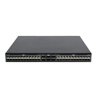
Preparing for installation This document is applicable to the H3C S6825-54HF switch (product code: LS-6825-54HF). Safety recommendations To avoid any equipment damage or bodily injury caused by incorrect use, read the following safety recommendations before installation. Note that the recommendations do not cover every possible hazardous condition. -
Page 9: Cleanliness
• High temperature can accelerate the aging of insulation materials and significantly lower the reliability and lifespan of the switch. For the temperature and humidity requirements of different switch models, see H3C S6825 Switch Series Hardware Information and Specifications. Cleanliness Dust buildup on the chassis might cause electrostatic adsorption and dust corrosion, resulting in poor contact of metal connectors and contact points. -
Page 10: Emi
CAUTION: As a best practice, control the corrosive gas concentrations in the equipment room at their average values. Make sure the corrosive gas concentrations do not exceed 30 minutes per day at their maximum values. To control corrosive gases, use the following guidelines: •... -
Page 11: Installation Tools
Installation tools No installation tools are provided with the switch. Prepare the following tools yourself: • Phillips screwdriver. • Flathead screwdriver. • ESD wrist strap. • Marker. Installation accessories Before installation, make sure you have all the required installation accessories. If any accessory is damaged or missing, use the part No. - Page 12 Part No. Description Quantity Serial console cable 04042967 Optional USB-to-RJ45 console cable 0404A1EE Optional Mini USB console cable User supplied SFP port dust plug Same number as the 14990101 SFP28 ports QSFP port dust plug Same number as the 1499A01G QSFP28 ports...
-
Page 13: Installing The Switch
Installing the switch CAUTION: Keep the tamper-proof seal on a mounting screw on the chassis cover intact, and if you want to open the chassis, contact H3C for permission. Otherwise, H3C shall not be liable for any consequence caused thereby. CAUTION: When installing the switch, always wear an ESD wrist strap and make sure the wrist strap makes good skin contact and is reliably grounded. -
Page 14: Installing The Switch In A 19-Inch Rack
Installing the switch in a 19-inch rack Accessories for switch rack-mounting Table2-2 Accessories for switch rack-mounting Mounting brackets Rack mounting rail kit 1U high, one pair • (provided). See Figure2-2. 1U rack mounting rail kit A, including one pair of chassis rails and one pair of long slide rails (provided). -
Page 15: Rack-Mounting Procedure At A Glance
Rack-mounting procedure at a glance Figure2-5 Rack-mounting procedure Select an installation Attach the Attach the Connect the position for the mounting mounting Attach the slide Mount the switch chassis rails to grounding cable to a brackets (near the power brackets to the rails to the rack in the rack the switch... -
Page 16: Attaching The Mounting Brackets, Chassis Rails, And Grounding Cable To The Chassis
Table2-3 Distance requirements between the front and rear rack posts Installation method Distance between the front and rear rack posts Using mounting brackets and rack 621 mm to 793 mm (24.45 in to 31.22 in) mounting rail kit A (long slide rails) Using mounting brackets and rack mounting rail kit B (super-short slide rails, 330 mm to 505 mm (12.99 in to 19.88 in) - Page 17 Figure2-8 Mounting bracket installation positions and grounding point positions (1) Mounting bracket installation position near the power supply side (2) Primary grounding point (3) Auxiliary grounding point (4) Mounting bracket installation position near the port side Attaching the mounting brackets and chassis rails to the chassis IMPORTANT: M4 screws are used to secure the mounting brackets and chassis rails to the switch.
- Page 18 Figure2-9 Attaching the mounting brackets and chassis rails to the chassis (mounting brackets installed near the port side, rack mounting rail kit A) Figure2-10 Attaching the mounting brackets and chassis rails to the chassis (mounting brackets installed near the port side, rack mounting rail kit B, narrow-spacing installation) Figure2-11 Attaching the mounting brackets and chassis rails to the chassis (mounting brackets installed near the port side, rack mounting rail kit B, wide-spacing installation) 2-11...
-
Page 19: Connecting The Grounding Cable To The Chassis
Figure2-12 Attaching the mounting brackets and chassis rails to the chassis (mounting brackets installed near the power supply side, rack mounting rail kit A) Figure2-13 Attaching the mounting brackets and chassis rails to the chassis (mounting brackets installed near the power supply side, rack mounting rail kit B, narrow-spacing installation) Figure2-14 Attaching the mounting brackets and chassis rails to the chassis (mounting brackets installed near the power supply side, rack mounting rail kit B, wide-spacing... - Page 20 Use M5 grounding screws to attach a grounding cable that has a two-hole grounding lug or single-hole grounding lug to the grounding point on the switch. If the grounding cable length or terminal type cannot meet your requirement, make an applicable grounding cable or contact H3C Support.
-
Page 21: Attaching The Slide Rails To The Rack
Attaching the slide rails to the rack IMPORTANT: M6 screws and cage nuts are used to attach the slide rails to the rack. Prepare M6 screws and cage nuts yourself. As a best practice, use a torque of 30 kgf-cm (2.94 Nm) to fasten the M6 screws. Before mounting the switch in the rack, you must attach slide rails to the rack. - Page 22 Attach cage nuts (user-supplied) to the front rack posts and make sure they are at the same level as the slide rails. One person performs the following operations: a. Supporting the bottom of the switch, aligns the chassis rails with the slide rails on the rack posts.
-
Page 23: Grounding The Switch By Using A Grounding Strip
Figure2-19 Mounting the switch in the rack (mounting brackets installed near the port side) Grounding the switch by using a grounding strip CAUTION: • Correctly connecting the grounding cable is crucial to lightning protection and EMI protection. • Do not connect the grounding cable to a fire main or lightning rod. •... -
Page 24: Installing And Removing A Fan Tray
As a best practice, make sure the power supplies and fan trays on the switch have the same airflow direction. For the fan trays available for the switch and their specifications, see H3C S6825 Switch Series Hardware Information and Specifications. Installing a fan tray CAUTION: To prevent damage to the fan tray or the connectors on the backplane, insert the fan tray gently. -
Page 25: Removing A Fan Tray
• Do not touch any bare wires and terminals on a fan tray. • Do not place a fan tray in a moist location or let liquid flow into it. • Contact H3C Support if the circuits or components on a fan tray are faulty. Do not remove any fan tray components. -
Page 26: Installing And Removing A Power Supply
As a best practice, install two power supplies of the same model for the switch. Select power supplies for the switch as required. For the power supplies available for the switch and their specifications, see H3C S6825 Switch Series Hardware Information and Specifications. Precautions •... -
Page 27: Removing A Power Supply
The installation procedure is the same for different models of power supplies. The following procedure installs a PSR450-12A power supply. To install a power supply: Wear an ESD wrist strap and make sure it makes good skin contact and is reliably grounded. Unpack the power supply and verify that the power supply model is correct. - Page 28 Removing a PSR450-12A/PSR450-12A1 power supply The removal procedure is the same for the PSR450-12A and PSR450-12A1 power supplies. The following procedure removes a PSR450-12A power supply. To remove a PSR450-12A power supply: Wear an ESD wrist strap and make sure it makes good skin contact and is reliably grounded. Remove the power cord.
-
Page 29: Connecting The Power Cord
Figure2-29 Removing the power cord from the power supply Hold the handle of the power supply with one hand, press the latch on the power supply towards the handle direction with your thumb, and pull the power supply part way out of the slot. Supporting the power supply bottom with the other, slowly pull the power supply out of the slot along the guide rails. -
Page 30: Connecting The Power Cord For A Psr450-12A/Psr450-12A1 Power Supply
Connecting the power cord for a PSR450-12A/PSR450-12A1 power supply Insert the female connector of the power cord supplied with the power supply into the power receptacle on the power supply. Use a releasable cable tie to secure the power cord to the handle of the power supply, as shown in Figure2-31. -
Page 31: Connecting The Dc Power Cord For A Psr450-12D Power Supply
Figure2-34 Connecting the power cord for a PSR450-12AHD power supply (3) Connecting the DC power cord for a PSR450-12D power supply Correctly orient the DC power cord connector and insert the connector into the power receptacle on the power supply. If you orient the DC power cord connector upside down, you cannot insert the connector into the power receptacle. -
Page 32: Verifying The Installation
Table2-5 Requirements for a suitable DC power cord Cross sectional Maximum Minimum cross Power supply Power cord area of the cross sectional sectional area of model connector provided power area of the the conductor cord conductor Use the connector of the 3.3 mm or 12 PSR450-12D... -
Page 33: Accessing The Switch For The First Time
The signal pinout for the RJ-45 connector of a serial console cable varies by vendor. To avoid abnormal configuration terminal display, use a serial console cable provided by H3C as shown in Table3-2. To prepare a serial console cable yourself, make sure the signal pinout for the RJ-45 connector is the same as that shown in Table3-3. -
Page 34: Connecting The Console Cable
Table3-2 Console cable views Product code for the Console cable type Console cable view recommended H3C console cable DB9-to-RJ45 console cable 04042967 USB-to-RJ45 console cable 0404A1EE Mini USB console cable User supplied, Connecting the console cable Connecting a DB9-to-RJ45 console cable... -
Page 35: Connecting A Usb-To-Rj45 Console Cable
Click the following link, or copy it to the address bar on your browser and download the USB-to-RJ45 console driver. http://www.h3c.com/en/home/USB_to_RJ45_Console/ View the TXT file named Read me in the Windows folder to check whether the Windows system of the configuration terminal supports the driver. - Page 36 Figure3-3 Driver installation wizard Click Finish after the drive installation is completed. Figure3-4 Finishing the driver installation Connect the standard USB connector of the cable to the USB port of the configuration terminal. 3-29...
-
Page 37: Connecting A Mini Usb Console Cable
After the startup completes, you can access the CLI to configure the switch. For more information about the configuration commands and CLI, see H3C S6805 & S6825 & S6850 & S9850 Switch Series Configuration Guides and H3C S6805 & S6825 & S6850 &... -
Page 38: Setting Up An Irf Fabric
Setting up an IRF fabric You can use H3C IRF technology to connect and virtualize multiple switches into a large virtual switch called an "IRF fabric" for flattened network topology, and high availability, scalability, and manageability. The switch can set up an IRF fabric only with switches from the same switch series. -
Page 39: Planning Irf Fabric Setup
IRF member switches will automatically elect a master. You can affect the election result by assigning a high member priority to the intended master switch. For more information about master election, see IRF configuration in H3C S6805 & S6825 & S6850 & S9850 Switch Series Virtual Technologies Configuration Guide. -
Page 40: Planning Irf Topology And Connections
Planning IRF topology and connections You can create an IRF fabric in daisy chain topology, or more reliably, ring topology. In ring topology, the failure of one IRF link does not cause the IRF fabric to split as in daisy chain topology. Rather, the IRF fabric changes to a daisy chain topology without interrupting network services. -
Page 41: Identifying Physical Irf Ports On The Member Switches
If the IRF member switches are all in one equipment room, use QSFP+/QSFP28 copper or fiber cables. For more information about transceiver modules and cables available for the switch, see H3C S6825 Switch Series Hardware Information and Specifications. The following subsections describe several H3C recommended IRF connection schemes by using QSFP28 transceiver modules and optical fibers, QSFP28 copper cables, and QSFP28 fiber cables. - Page 42 Figure4-4 Connecting the switches in one rack Figure4-5 IRF fabric topology IRF-port2 IRF-port1 IRF-port2 IRF-port1 IRF-port2 IRF-port1 IRF-port2 IRF-port1 Connecting the IRF member switches in a ToR solution You can install IRF member switches in different racks side by side to deploy a top of rack (ToR) solution.
-
Page 43: Configuring Basic Irf Settings
IRF settings, including their member IDs, member priorities, and IRF port bindings. For the approaches to accessing the switch, see login management in H3C S6805 & S6825 & S6850 & S9850 Switch Series Fundamentals Configuration Guide. -
Page 44: Maintenance And Troubleshooting
The status LED on a power supply is not steady green (active state) or flashing green (standby state). You can use the status LED on a power supply to identify a power supply failure. For more information about the status LED on a power supply, see H3C PSR450 Power Module Series User Manual. Solution To resolve the issue: Verify that the power cord is correctly connected. - Page 45 Stop bits—1. Parity—None. Flow control—None. If the issue persists, contact H3C Support. Garbled display on the configuration terminal Symptom The configuration terminal displays garbled text when the switch is powered on. Solution To resolve the issue: Verify that the terminal parameter settings are correct: Baud rate—9600.
Need help?
Do you have a question about the S6825 Series and is the answer not in the manual?
Questions and answers