H3C S6825 Series Installation Manual
Hide thumbs
Also See for S6825 Series:
- Installation manual (45 pages) ,
- Troubleshooting manual (58 pages) ,
- Configuration manual (38 pages)

Related Manuals for H3C S6825 Series


Summary of Contents for H3C S6825 Series
- Page 1 H3C S6825 Switch Series Installation Guide New H3C Technologies Co., Ltd. http://www.h3c.com Document version: 5W100-20200810...
- Page 2 The information in this document is subject to change without notice. All contents in this document, including statements, information, and recommendations, are believed to be accurate, but they are presented without warranty of any kind, express or implied. H3C shall not be liable for technical or editorial errors or omissions contained herein.
- Page 3 Preface H3C S6825 Switch Series Installation Guide describes the appearance, installation, power-on, maintenance, and troubleshooting of the H3C S6825 Switch Series. This preface includes the following topics about the documentation: • Audience. • Conventions. • Documentation feedback. Audience This documentation is intended for: •...
- Page 4 Symbols Convention Description An alert that calls attention to important information that if not understood or followed WARNING! can result in personal injury. An alert that calls attention to important information that if not understood or followed CAUTION: can result in data loss, data corruption, or damage to hardware or software. An alert that calls attention to essential information.
- Page 5 Documentation feedback You can e-mail your comments about product documentation to info@h3c.com. We appreciate your comments.
-
Page 6: Table Of Contents
Contents 1 Preparing for installation ······························································· 1-1 Safety recommendations ·········································································································· 1-1 Examining the installation site ···································································································· 1-1 Temperature/humidity ······································································································· 1-1 Cleanliness ····················································································································· 1-2 EMI ······························································································································· 1-2 Laser safety ···················································································································· 1-3 Installation tools ······················································································································ 1-3 Installation accessories ············································································································ 1-3 2 Installing the switch ····································································· 2-5 Installing the switch in a 19-inch rack ··························································································... - Page 7 Symptom ······················································································································ 5-35 Solution ························································································································ 5-35 Configuration terminal display issues ························································································ 5-35 No display on the configuration terminal ·············································································· 5-35 Garbled display on the configuration terminal ······································································· 5-36 6 Appendix A Chassis views and technical specifications ····················· 6-37 Chassis views ······················································································································ 6-37 S6825-54HF ··················································································································...
-
Page 8: Preparing For Installation
Preparing for installation This document is applicable to H3C S6825-54HF switch (BOM code: 0235A2LJ, product code: LS-6825-54HF). Safety recommendations To avoid any equipment damage or bodily injury caused by incorrect use, read the following safety recommendations before installation. Note that the recommendations do not cover every possible hazardous condition. -
Page 9: Cleanliness
• Lasting low relative humidity can cause washer contraction and ESD and cause problems including loose screws and circuit failure. • High temperature can accelerate the aging of insulation materials and significantly lower the reliability and lifespan of the switch. For the temperature and humidity requirements of different switch models, see "Appendix A Chassis views and technical... -
Page 10: Laser Safety
• To prevent signal ports from getting damaged by overvoltage or overcurrent caused by lightning strikes, route interface cables only indoors. Laser safety WARNING! Disconnected optical fibers or transceiver modules might emit invisible laser light. Do not stare into beams or view directly with optical instruments when the switch is operating. The switch is a Class 1M laser device. - Page 11 Part No. Description Quantity Grounding cable 0404A0KM 1 (provided) Grounding screw 2 (provided) Power supply filler panel 2114A09C 1 (provided) Releasable cable tie User supplied Serial console cable 04042967 1 (provided) SFP port dust plug Same number as 14990101 the SFP28 ports QSFP port dust plug Same number as 1499A01G...
-
Page 12: Installing The Switch
Installing the switch CAUTION: Keep the tamper-proof seal on a mounting screw on the chassis cover intact, and if you want to open the chassis, contact H3C for permission. Otherwise, H3C shall not be liable for any consequence caused thereby. CAUTION: When installing the switch, always wear an ESD wrist strap and make sure the wrist strap makes good skin contact and is reliably grounded. -
Page 13: Installing The Switch In A 19-Inch Rack
Installing the switch in a 19-inch rack Accessories for switch rack-mounting Table2-2 Accessories for switch rack-mounting Mounting brackets Rack mounting rail kit • 1U rack mounting rail kit A, including one pair of chassis rails and one pair of long slide rails (provided). See Figure2-3. 1U high, one pair •... -
Page 14: Rack-Mounting Procedure At A Glance
Rack-mounting procedure at a glance Figure2-5 Rack-mounting procedure Select an installation Attach the Attach the Connect the position for the mounting mounting Attach the slide Mount the switch chassis rails to grounding cable to a brackets (near the power brackets to the rails to the rack in the rack the switch... -
Page 15: Attaching The Mounting Brackets, Chassis Rails, And Grounding Cable To The Chassis
Table2-3 Distance requirements between the front and rear rack posts Installation method Distance between the front and rear rack posts Using mounting brackets and rack 621 mm to 793 mm (24.45 in to 31.22 in) mounting rail kit A (long slide rails) Using mounting brackets and rack mounting rail kit B (super-short slide rails, 330 mm to 505 mm (12.99 in to 19.88 in) - Page 16 Figure2-8 Mounting bracket installation positions and grounding point positions (1) Mounting bracket installation position near the power supply side (2) Primary grounding point (3) Auxiliary grounding point (4) Mounting bracket installation position near the port side Attaching the mounting brackets and chassis rails to the chassis IMPORTANT: M4 screws are used to secure the mounting brackets and chassis rails to the switch.
- Page 17 Figure2-9 Attaching the mounting brackets and chassis rails to the chassis (mounting brackets installed near the port side, rack mounting rail kit A) Figure2-10 Attaching the mounting brackets and chassis rails to the chassis (mounting brackets installed near the port side, rack mounting rail kit B, narrow-spacing installation) Figure2-11 Attaching the mounting brackets and chassis rails to the chassis (mounting brackets installed near the port side, rack mounting rail kit B, wide-spacing installation) 2-10...
-
Page 18: Connecting The Grounding Cable To The Chassis
Figure2-12 Attaching the mounting brackets and chassis rails to the chassis (mounting brackets installed near the power supply side, rack mounting rail kit A) Figure2-13 Attaching the mounting brackets and chassis rails to the chassis (mounting brackets installed near the power supply side, rack mounting rail kit B, narrow-spacing installation) Figure2-14 Attaching the mounting brackets and chassis rails to the chassis (mounting brackets installed near the power supply side, rack mounting rail kit B, wide-spacing... -
Page 19: Attaching The Slide Rails To The Rack
grounding cable to a grounding point before you mount the switch in the rack. Select the primary or auxiliary grounding point as required. The procedure is the same for connecting the grounding cable to the primary and auxiliary grounding points. The following procedure connects the grounding cable to the primary grounding point (near the power supply side). -
Page 20: Mounting The Switch In The Rack
Figure2-16 Installing the 1U long slide rails Mounting the switch in the rack This task requires two people. To mount the switch in the rack: Wear an ESD wrist strap and make sure it makes good skin contact and is reliably grounded. Verify that the mounting brackets and chassis rails have been securely attached to the switch chassis. - Page 21 Figure2-17 Mounting the switch in the rack (mounting brackets installed near the power supply side) Figure2-18 Mounting the switch in the rack (mounting brackets installed near the port side) 2-14...
-
Page 22: Grounding The Switch By Using A Grounding Strip
• For information about lightning protection for the switch, see H3C Lightning Protection Guide. The power input end of the switch has a noise filter, whose central ground is directly connected to the chassis to form the chassis ground (commonly known as PGND). -
Page 23: Installing And Removing A Fan Tray
• Do not touch any bare wires and terminals on a fan tray. • Do not place a fan tray in a moist location or let liquid flow into it. • Contact H3C Support if the circuits or components on a fan tray are faulty. Do not remove any fan tray components. -
Page 24: Installing And Removing A Power Supply
To remove an LSPM1FANSA or LSPM1FANSB fan tray: Wear an ESD wrist strap and make sure it makes good skin contact and is reliably grounded. Press the fan tray handles towards each other to release the fan tray and slowly pull the fan tray out of the slot along the guide rails. -
Page 25: Removing A Power Supply
To install a power supply: Wear an ESD wrist strap and make sure it makes good skin contact and is reliably grounded. Unpack the power supply and verify that the power supply model is correct. Correctly orient the power supply with the lettering on it upward. Grasp the handle of the power supply with one hand and support its bottom with the other, and slide the power supply slowly along the guide rails into the slot. - Page 26 To remove a PSR450-12A power supply: Wear an ESD wrist strap and make sure it makes good skin contact and is reliably grounded. Remove the power cord. Hold the handle of the power supply with one hand, press the latch on the power supply towards the handle direction with your thumb, and pull the power supply part way out of the slot, as shown in Figure2-26.
-
Page 27: Connecting The Power Cord
Figure2-28 Removing the power cord from the power supply Hold the handle of the power supply with one hand, press the latch on the power supply towards the handle direction with your thumb, and pull the power supply part way out of the slot. Supporting the power supply bottom with the other, slowly pull the power supply out of the slot along the guide rails. -
Page 28: Connecting The Power Cord For A Psr450-12A/Psr450-12A1 Power Supply
Connecting the power cord for a PSR450-12A/PSR450-12A1 power supply Insert the female connector of the power cord supplied with the power supply into the power receptacle on the power supply. Use a releasable cable tie to secure the power cord to the handle of the power supply, as shown in Figure2-30. -
Page 29: Connecting The Dc Power Cord For A Psr450-12D Power Supply
Figure2-33 Connecting the power cord for a PSR450-12AHD power supply (3) Connecting the DC power cord for a PSR450-12D power supply Correctly orient the DC power cord connector and insert the connector into the power receptacle on the power supply. If you orient the DC power cord connector upside down, you cannot insert the connector into the power receptacle. - Page 30 • There is enough space for heat dissipation around the switch, and the rack is stable. • The grounding cable is securely connected. • The power source is as required by the switch. • The power cords are correctly connected. •...
-
Page 31: Accessing The Switch For The First Time
Accessing the switch for the first time Setting up the configuration environment You can access the switch from the serial console port or the mini USB console port. As a best practice, use the serial console port to access the switch (the switch is provided with a serial console cable). -
Page 32: Connecting A Mini Usb Console Cable
Connect the USB mini Type B connector to the Mini USB console port on the switch. Click http://www.h3c.com/en/home/USB_Console/, or copy it to the address bar on the browser to log in to download page of the USB console driver, and download the driver. - Page 33 Figure3-3 Device Driver Installation Wizard Click Continue Anyway if the following dialog box appears. Figure3-4 Software Installation Click Finish. 3-26...
-
Page 34: Setting Terminal Parameters
Figure3-5 Completing the device driver installation wizard Setting terminal parameters To configure and manage the switch through the serial console port or mini USB console port, you must run a terminal emulator program, TeraTermPro or PuTTY, on your configuration terminal. You can use the emulator program to connect a network device, a Telnet site, or an SSH site. - Page 35 After the startup completes, you can access the CLI to configure the switch. For more information about the configuration commands and CLI, see H3C S6805 & S6825 & S6850 & S9850 Switch Series Configuration Guides and H3C S6805 & S6825 & S6850 &...
-
Page 36: Setting Up An Irf Fabric
Setting up an IRF fabric You can use H3C IRF technology to connect and virtualize multiple switches into a large virtual switch called an "IRF fabric" for flattened network topology, and high availability, scalability, and manageability. The switch can set up an IRF fabric only with switches from the same switch series. -
Page 37: Planning Irf Fabric Setup
IRF member switches will automatically elect a master. You can affect the election result by assigning a high member priority to the intended master switch. For more information about master election, see IRF configuration in H3C S6805 & S6825 & S6850 & S9850 Switch Series Virtual Technologies Configuration Guide. -
Page 38: Planning Irf Topology And Connections
Planning IRF topology and connections You can create an IRF fabric in daisy chain topology, or more reliably, ring topology. In ring topology, the failure of one IRF link does not cause the IRF fabric to split as in daisy chain topology. Rather, the IRF fabric changes to a daisy chain topology without interrupting network services. -
Page 39: Identifying Physical Irf Ports On The Member Switches
"Appendix C Ports and LEDs." The following subsections describe several H3C recommended IRF connection schemes by using QSFP28 transceiver modules and optical fibers, QSFP28 copper cables, and QSFP28 fiber cables. All these schemes use a ring topology. - Page 40 Figure4-4 Connecting the switches in one rack Figure4-5 IRF fabric topology IRF-port2 IRF-port1 IRF-port2 IRF-port1 IRF-port2 IRF-port1 IRF-port2 IRF-port1 Connecting the IRF member switches in a ToR solution You can install IRF member switches in different racks side by side to deploy a top of rack (ToR) solution.
-
Page 41: Configuring Basic Irf Settings
IRF settings, including their member IDs, member priorities, and IRF port bindings. For the approaches to accessing the switch, see login management in H3C S6805 & S6825 & S6850 & S9850 Switch Series Fundamentals Configuration Guide. -
Page 42: Maintenance And Troubleshooting
The status LED on a power supply is not steady green (active state) or flashing green (standby state). You can use the status LED on a power supply to identify a power supply failure. For more information about the status LED on a power supply, see H3C PSR450 Power Module Series User Manual. Solution To resolve the issue: Verify that the power cord is correctly connected. -
Page 43: Garbled Display On The Configuration Terminal
Stop bits—1. Parity—None. Flow control—None. If the issue persists, contact H3C Support. Garbled display on the configuration terminal Symptom The configuration terminal displays garbled text when the switch is powered on. Solution To resolve the issue: Verify that the terminal parameter settings are correct: Baud rate—9600. -
Page 44: Appendix A Chassis Views And Technical Specifications
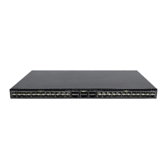
Appendix A Chassis views and technical specifications Chassis views S6825-54HF Figure6-1 Front panel (1) SFP28 port (2) SFP28 port LED (3) QSFP28 port (4) QSFP28 port LED Figure6-2 Rear panel (1) Fiber management Ethernet port (2) Console port (3) Mini USB console port (4) USB port (5) Fan tray 1 (6) Fan tray 2... -
Page 45: Technical Specifications
information about installing and removing a power supply, see "Installing and removing a power supply." The switch comes with the five fan tray slots empty. You must install five fan trays of the same model for the switch. In Figure6-2, five LSPM1FANSA fan trays are installed on the switch. For more information about installing and removing a fan tray, see "Installing and removing a fan tray."... - Page 46 Item Specification • Max voltage range: –36 to –72 VDC PSR450-12A/PSR450-12A1: • Single AC input: 78 W • Dual AC inputs: 87 W PSR450-12AHD: Minimum power • Single DC input: 77 W consumption • Dual DC inputs: 84 W PSR450-12D: •...
-
Page 47: Appendix B Frus And Compatibility Matrixes
For more information the power supply side about the power Max input voltage range: 90 to 290 VAC @ 47 to to the port side) supplies, see H3C 63 Hz PSR450-12A1 (with PSR450 Power Max output power: 450 W ... -
Page 48: Fan Trays
Input voltage 12 V Maximum power 9.8 W consumption Documentation reference H3C LSPM1FANSA & LSPM1FANSB Fan Trays User Guide LSPM1FANSB Dimensions 41 × 40 × 105 mm (1.61 × 1.57 × 4.13 in), including the handle Fan number Fan speed 20000 R.P.M... -
Page 49: Appendix C Ports And Leds
• As a best practice, use H3C transceiver modules and cables for the switch. • The H3C transceiver modules and cables are subject to change over time. For the most up-to-date list of H3C transceiver modules and cables, contact H3C Support or marketing staff. -
Page 50: Usb Port
IMPORTANT: • USB devices from different vendors vary in compatibility and driver. H3C does not guarantee correct operation of all USB devices on the switch. If a USB device fails to operate on the switch, replace it with one from another vendor. - Page 51 • SFP+ copper cables in Table8-9. • SFP+ fiber cables in Table8-10. • 1-GE SFP transceiver modules in Table8-11. IMPORTANT: When connecting an SFP28 port on the switch to a peer port, follow these guidelines: • To use an SFP28 or SFP+ copper cable, you must configure the speed and the duplex mode for the SFP28 port and the peer port if the peer port does not support autonegotiation of the speed and duplex mode.
- Page 52 Table8-8 10-GE SFP+ transceiver modules available for the SFP28 ports 10-GE SFP+ Central Modal Fiber type and transceiver waveleng Connector bandwidth transmission diameter (µm) module th (nm) (MHz × km) distance 2000 300 m (984.25 ft) Multi-mode, 82 m (269.03 ft) 50/125 SFP-XG-SX-MM 66 m (216.54 ft)
-
Page 53: Qsfp28 Port
1-GE SFP Central Cable/Fiber Modal transceiver wavelength Connector type and bandwidth transmission module (nm) diameter (µm) (MHz × km) distance Single-mode, 10 km (6.21 miles) 9/125 SFP-GE-LX-SM Multi-mode, 1310 500 or 400 550 m (1804.46 ft) 1310-A 50/125 Multi-mode, 550 m (1804.46 ft) 62.5/125 SFP-GE-LH40- Single-mode,... - Page 54 Central Cable/Fiber Modal Model wavelength Connector type and bandwidth transmission (nm) diameter (µm) (MHz × km) distance Four lanes: • 1271 QSFP-100G-L Single-mode, 2 km (1.24 • R4L-WDM130 1291 9/125 miles) • 1311 • 1331 Four lanes: • 1295.56 QSFP-100G- Single-mode, 40 km (24.86 •...
-
Page 55: Leds
QSFP+ Central Fiber type Modal transceiver wavelength Connector and diameter bandwidth transmission module (nm) (µm) (MHz × km) distance Four lanes: • 1271 QSFP-40G-LR4 Single-mode, • 1291 10 km (6.21 miles) -WDM1300 9/125 • 1311 • 1331 Four lanes: • 1271 QSFP-40G-LR4 Single-mode,... -
Page 56: Sfp28 Port Led
The switch is powered off or has failed to start up. SFP28 port LED Each SFP28 port has a status LED to show its operating status and activities. Table8-19 SFP28 port LED description LED status Description A transceiver module or cable has been correctly installed. The port has a link Steady green and is operating at 25 Gbps. -
Page 57: Fan Tray Alarm Leds
Table8-22 Fiber management Ethernet port LED description LED mark Status Description No link is present. Steady green The port is operating at 1000 Mbps and a link is present. LINK/ACT Flashing green The port is receiving or sending data at 1000 Mbps. Steady yellow The port is operating at 100 Mbps and a link is present. - Page 58 Figure9-2 Airflow from the port side to the power supply side (with LSPM1FANSB fan trays) 9-51...
-
Page 59: Index
Index A C E F G I L M N P Q R S T U Accessories for switch rack-mounting,2-6 Management Ethernet port,8-42 Attaching the mounting brackets, chassis rails, and Management Ethernet port LEDs,8-49 grounding cable to the chassis,2-8 Mounting the switch in the rack,2-13 Attaching the slide rails to the rack,2-12...
Need help?
Do you have a question about the S6825 Series and is the answer not in the manual?
Questions and answers