Table of Contents
Advertisement
Quick Links
Contents
1 Preparing for installation ·········································································· 1-1
Safety recommendations ································································································································ 1-1
Examining the installation site ························································································································· 1-1
Temperature/humidity ····························································································································· 1-1
Cleanliness ·············································································································································· 1-2
EMI ·························································································································································· 1-2
Laser safety ············································································································································· 1-3
Installation tools ·············································································································································· 1-3
Installation accessories ··································································································································· 1-3
2 Installing the switch ·················································································· 2-5
Installing the switch in a 19-inch rack·············································································································· 2-6
Accessories for switch rack-mounting ····································································································· 2-6
Rack-mounting procedure at a glance ···································································································· 2-7
Chassis dimensions and rack requirements ··························································································· 2-7
Attaching the mounting brackets, chassis rails, and grounding cable to the chassis······························ 2-8
Connecting the grounding cable to the chassis ···················································································· 2-11
Attaching the slide rails to the rack ······································································································· 2-12
Mounting the switch in the rack ············································································································· 2-13
Grounding the switch by using a grounding strip ·························································································· 2-15
Installing and removing a fan tray ················································································································· 2-16
Installing a fan tray ································································································································ 2-16
Removing a fan tray ······························································································································ 2-17
Installing and removing a power supply ········································································································ 2-17
Precautions ··········································································································································· 2-17
Installing a power supply ······················································································································· 2-18
Removing a power supply ····················································································································· 2-19
Connecting the power cord ··························································································································· 2-21
Connecting the power cord for a PSR450-12A/PSR450-12A1 power supply ······································· 2-21
Connecting the power cord for a PSR450-12AHD power supply·························································· 2-22
Connecting the DC power cord for a PSR450-12D power supply ························································ 2-23
Verifying the installation ································································································································ 2-23
3 Accessing the switch for the first time ···················································· 3-24
Setting up the configuration environment ····································································································· 3-24
Connecting the serial console cable ····································································································· 3-24
Connecting a mini USB console cable ·································································································· 3-25
Setting terminal parameters ·················································································································· 3-27
Starting the switch ········································································································································· 3-27
4 Setting up an IRF fabric ········································································· 4-29
IRF fabric setup flowchart ····························································································································· 4-29
Planning IRF fabric setup ······························································································································ 4-30
Planning IRF fabric size and the installation site ··················································································· 4-30
Identifying the master switch and planning IRF member IDs ································································ 4-30
Planning IRF topology and connections································································································ 4-31
Identifying physical IRF ports on the member switches ········································································ 4-32
Planning the cabling scheme ················································································································ 4-32
Configuring basic IRF settings ······················································································································ 4-34
Connecting the physical IRF ports ················································································································ 4-34
Accessing the IRF fabric to verify the configuration ······················································································ 4-34
5 Maintenance and troubleshooting ·························································· 5-35
Power supply failure ······································································································································ 5-35
Symptom ··············································································································································· 5-35
Solution ················································································································································· 5-35
Fan tray failure ·············································································································································· 5-35
i
Advertisement
Table of Contents

Related Manuals for H3C S6825-54HF


Summary of Contents for H3C S6825-54HF
-
Page 1: Table Of Contents
Contents 1 Preparing for installation ·········································································· 1-1 Safety recommendations ································································································································ 1-1 Examining the installation site ························································································································· 1-1 Temperature/humidity ····························································································································· 1-1 Cleanliness ·············································································································································· 1-2 EMI ·························································································································································· 1-2 Laser safety ············································································································································· 1-3 Installation tools ·············································································································································· 1-3 Installation accessories ··································································································································· 1-3 2 Installing the switch ·················································································· 2-5 Installing the switch in a 19-inch rack··············································································································... - Page 2 Symptom ··············································································································································· 5-35 Solution ················································································································································· 5-35 Configuration terminal display issues············································································································ 5-35 No display on the configuration terminal ······························································································· 5-35 Garbled display on the configuration terminal ······················································································· 5-36...
-
Page 3: Preparing For Installation
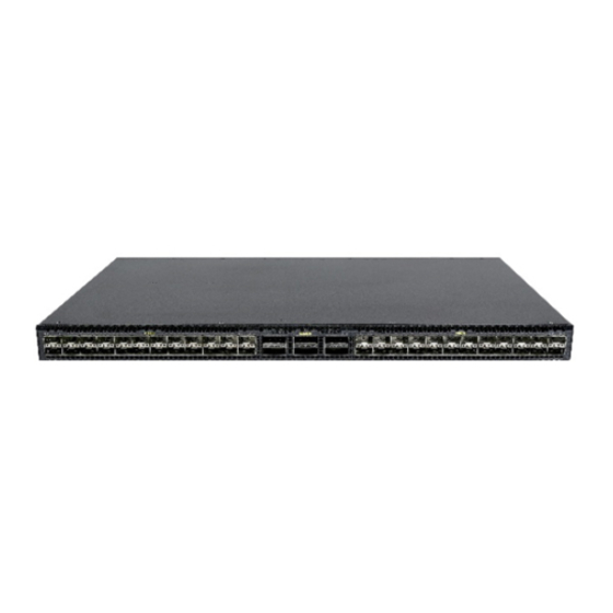
Preparing for installation This document is applicable to the H3C S6825-54HF switch (BOM code: 0235A2LJ, product code: LS-6825-54HF). Safety recommendations To avoid any equipment damage or bodily injury caused by incorrect use, read the following safety recommendations before installation. Note that the recommendations do not cover every possible hazardous condition. -
Page 4: Cleanliness
• Lasting low relative humidity can cause washer contraction and ESD and cause problems including loose screws and circuit failure. • High temperature can accelerate the aging of insulation materials and significantly lower the reliability and lifespan of the switch. For the temperature and humidity requirements of different switch models, see the hardware information and specifications for the switch. -
Page 5: Laser Safety
• If AC power is used, use a single-phase three-wire power receptacle with protection earth (PE) to filter interference from the power grid. • Keep the switch far away from radio transmitting stations, radar stations, and high-frequency devices. • Use electromagnetic shielding, for example, shielded interface cables, when necessary. •... - Page 6 Part No. Description Quantity Grounding cable 0404A0KM 1 (provided) Grounding screw 2 (provided) Power supply filler panel 2114A09C 1 (provided) Releasable cable tie User supplied Serial console cable 04042967 1 (provided) SFP port dust plug Same number as 14990101 the SFP28 ports QSFP port dust plug Same number as 1499A01G...
-
Page 7: Installing The Switch
Installing the switch CAUTION: Keep the tamper-proof seal on a mounting screw on the chassis cover intact, and if you want to open the chassis, contact H3C for permission. Otherwise, H3C shall not be liable for any consequence caused thereby. CAUTION: When installing the switch, always wear an ESD wrist strap and make sure the wrist strap makes good skin contact and is reliably grounded. -
Page 8: Installing The Switch In A 19-Inch Rack
Installing the switch in a 19-inch rack Accessories for switch rack-mounting Table2-2 Accessories for switch rack-mounting Mounting brackets Rack mounting rail kit • 1U rack mounting rail kit A, including one pair of chassis rails and one pair of long slide rails (provided). See Figure2-3. 1U high, one pair •... -
Page 9: Rack-Mounting Procedure At A Glance
Rack-mounting procedure at a glance Figure2-5 Rack-mounting procedure Select an installation Attach the Attach the Connect the position for the mounting mounting Attach the slide Mount the switch chassis rails to grounding cable to a brackets (near the power brackets to the rails to the rack in the rack the switch... -
Page 10: Attaching The Mounting Brackets, Chassis Rails, And Grounding Cable To The Chassis
Table2-3 Distance requirements between the front and rear rack posts Installation method Distance between the front and rear rack posts Using mounting brackets and rack 621 mm to 793 mm (24.45 in to 31.22 in) mounting rail kit A (long slide rails) Using mounting brackets and rack mounting rail kit B (super-short slide rails, 330 mm to 505 mm (12.99 in to 19.88 in) - Page 11 Figure2-8 Mounting bracket installation positions and grounding point positions (1) Mounting bracket installation position near the power supply side (2) Primary grounding point (3) Auxiliary grounding point (4) Mounting bracket installation position near the port side Attaching the mounting brackets and chassis rails to the chassis IMPORTANT: M4 screws are used to secure the mounting brackets and chassis rails to the switch.
- Page 12 Figure2-9 Attaching the mounting brackets and chassis rails to the chassis (mounting brackets installed near the port side, rack mounting rail kit A) Figure2-10 Attaching the mounting brackets and chassis rails to the chassis (mounting brackets installed near the port side, rack mounting rail kit B, narrow-spacing installation) Figure2-11 Attaching the mounting brackets and chassis rails to the chassis (mounting brackets installed near the port side, rack mounting rail kit B, wide-spacing installation) 2-10...
-
Page 13: Connecting The Grounding Cable To The Chassis
Figure2-12 Attaching the mounting brackets and chassis rails to the chassis (mounting brackets installed near the power supply side, rack mounting rail kit A) Figure2-13 Attaching the mounting brackets and chassis rails to the chassis (mounting brackets installed near the power supply side, rack mounting rail kit B, narrow-spacing installation) Figure2-14 Attaching the mounting brackets and chassis rails to the chassis (mounting brackets installed near the power supply side, rack mounting rail kit B, wide-spacing... -
Page 14: Attaching The Slide Rails To The Rack
grounding cable to a grounding point before you mount the switch in the rack. Select the primary or auxiliary grounding point as required. The procedure is the same for connecting the grounding cable to the primary and auxiliary grounding points. The following procedure connects the grounding cable to the primary grounding point (near the power supply side). -
Page 15: Mounting The Switch In The Rack
Figure2-16 Installing the 1U long slide rails Mounting the switch in the rack This task requires two people. To mount the switch in the rack: Wear an ESD wrist strap and make sure it makes good skin contact and is reliably grounded. Verify that the mounting brackets and chassis rails have been securely attached to the switch chassis. - Page 16 Figure2-17 Mounting the switch in the rack (mounting brackets installed near the power supply side) Figure2-18 Mounting the switch in the rack (mounting brackets installed near the port side) 2-14...
-
Page 17: Grounding The Switch By Using A Grounding Strip
• For information about lightning protection for the switch, see H3C Lightning Protection Guide. The power input end of the switch has a noise filter, whose central ground is directly connected to the chassis to form the chassis ground (commonly known as PGND). -
Page 18: Installing And Removing A Fan Tray
Installing and removing a fan tray CAUTION: • For adequate heat dissipation, you must install five fan trays of the same model for the switch. • Make sure all slots have a module installed when the switch is operating. • If more than one fan tray fails during switch operation, do not remove the failed fan trays simultaneously. -
Page 19: Removing A Fan Tray
• Do not touch any bare wires and terminals on a fan tray. • Do not place a fan tray in a moist location or let liquid flow into it. • Contact H3C Support if the circuits or components on a fan tray are faulty. Do not remove any fan tray components. -
Page 20: Installing A Power Supply
Figure2-23 Removal procedure Turn off the circuit Disconnect the power Remove the power breaker cord supply • If a power supply slot is empty, install a filler panel in it to ensure adequate heat dissipation. Installing a power supply The installation procedure is the same for different models of power supplies. The following procedure installs a PSR450-12A power supply. -
Page 21: Removing A Power Supply
Removing a power supply CAUTION: When the switch has two power supplies in 1+1 redundancy mode, removing one power supply does not affect the operation of the switch. When the switch has only one power supply installed, removing the power supply powers off the switch. Removing a PSR450-12A/PSR450-12A1 power supply The removal procedure is the same for the PSR450-12A and PSR450-12A1 power supplies. - Page 22 Figure2-27 Opening the cable clamp Figure2-28 Removing the power cord from the power supply Hold the handle of the power supply with one hand, press the latch on the power supply towards the handle direction with your thumb, and pull the power supply part way out of the slot. Supporting the power supply bottom with the other, slowly pull the power supply out of the slot along the guide rails.
-
Page 23: Connecting The Power Cord
Figure2-29 Removing a PSR450-12D power supply (1) Use a flat-head screwdriver to loosen the screws on the power cord connector (2) Pull the power cord connector out Connecting the power cord WARNING! Provide a circuit breaker for each power input. When you connect a power cord, make sure the circuit breaker is switched off. -
Page 24: Connecting The Power Cord For A Psr450-12Ahd Power Supply
Connecting the power cord for a PSR450-12AHD power supply Slide the cable clamp onto the tie mount on the power supply, as shown in Figure2-31. Connect the female connector of the power cord to the power receptacle on the power supply, as shown in Figure2-32 Close the cable clamp and slide it forward until it is flush against the edge of the female... -
Page 25: Connecting The Dc Power Cord For A Psr450-12D Power Supply
Connecting the DC power cord for a PSR450-12D power supply Correctly orient the DC power cord connector and insert the connector into the power receptacle on the power supply. If you orient the DC power cord connector upside down, you cannot insert the connector into the power receptacle. -
Page 26: Accessing The Switch For The First Time
Accessing the switch for the first time Setting up the configuration environment You can access the switch from the serial console port or the mini USB console port. As a best practice, use the serial console port to access the switch (the switch is provided with a serial console cable). -
Page 27: Connecting A Mini Usb Console Cable
Connect the USB mini Type B connector to the Mini USB console port on the switch. Click http://www.h3c.com/en/home/USB_Console/, or copy it to the address bar on the browser to log in to download page of the USB console driver, and download the driver. - Page 28 Figure3-3 Device Driver Installation Wizard Click Continue Anyway if the following dialog box appears. Figure3-4 Software Installation Click Finish. 3-26...
-
Page 29: Setting Terminal Parameters
Figure3-5 Completing the device driver installation wizard Setting terminal parameters To configure and manage the switch through the serial console port or mini USB console port, you must run a terminal emulator program, TeraTermPro or PuTTY, on your configuration terminal. You can use the emulator program to connect a network device, a Telnet site, or an SSH site. - Page 30 After the startup completes, you can access the CLI to configure the switch. For more information about the configuration commands and CLI, see H3C S6805 & S6825 & S6850 & S9850 Switch Series Configuration Guides and H3C S6805 & S6825 & S6850 &...
-
Page 31: Setting Up An Irf Fabric
Setting up an IRF fabric You can use H3C IRF technology to connect and virtualize multiple switches into a large virtual switch called an "IRF fabric" for flattened network topology, and high availability, scalability, and manageability. The switch can set up an IRF fabric only with switches from the same switch series. -
Page 32: Planning Irf Fabric Setup
IRF member switches will automatically elect a master. You can affect the election result by assigning a high member priority to the intended master switch. For more information about master election, see IRF configuration in H3C S6805 & S6825 & S6850 & S9850 Switch Series Virtual Technologies Configuration Guide. -
Page 33: Planning Irf Topology And Connections
Planning IRF topology and connections You can create an IRF fabric in daisy chain topology, or more reliably, ring topology. In ring topology, the failure of one IRF link does not cause the IRF fabric to split as in daisy chain topology. Rather, the IRF fabric changes to a daisy chain topology without interrupting network services. -
Page 34: Identifying Physical Irf Ports On The Member Switches
QSFP+/QSFP28 copper or fiber cables. For more information about transceiver modules and cables available for the switch, see the hardware information and specifications for the switch. The following subsections describe several H3C recommended IRF connection schemes by using QSFP28 transceiver modules and optical fibers, QSFP28 copper cables, and QSFP28 fiber cables. - Page 35 Figure4-4 Connecting the switches in one rack Figure4-5 IRF fabric topology IRF-port2 IRF-port1 IRF-port2 IRF-port1 IRF-port2 IRF-port1 IRF-port2 IRF-port1 Connecting the IRF member switches in a ToR solution You can install IRF member switches in different racks side by side to deploy a top of rack (ToR) solution.
-
Page 36: Configuring Basic Irf Settings
IRF settings, including their member IDs, member priorities, and IRF port bindings. For the approaches to accessing the switch, see login management in H3C S6805 & S6825 & S6850 & S9850 Switch Series Fundamentals Configuration Guide. -
Page 37: Maintenance And Troubleshooting
The status LED on a power supply is not steady green (active state) or flashing green (standby state). You can use the status LED on a power supply to identify a power supply failure. For more information about the status LED on a power supply, see H3C PSR450 Power Module Series User Manual. Solution To resolve the issue: Verify that the power cord is correctly connected. - Page 38 Stop bits—1. Parity—None. Flow control—None. If the issue persists, contact H3C Support. Garbled display on the configuration terminal Symptom The configuration terminal displays garbled text when the switch is powered on. Solution To resolve the issue: Verify that the terminal parameter settings are correct: Baud rate—9600.
Need help?
Do you have a question about the S6825-54HF and is the answer not in the manual?
Questions and answers