
Related Manuals for H3C S6826 Series


Summary of Contents for H3C S6826 Series
- Page 1 H3C S6826 & S9826 Switch Series Installation Guide New H3C Technologies Co., Ltd. http://www.h3c.com Document version: 5W100-20211129...
- Page 2 The information in this document is subject to change without notice. All contents in this document, including statements, information, and recommendations, are believed to be accurate, but they are presented without warranty of any kind, express or implied. H3C shall not be liable for technical or editorial errors or omissions contained herein.
- Page 3 Preface H3C S6826 & S9826 Switch Series Installation Guide describes the appearance, installation, power-on, maintenance, and troubleshooting of the H3C S6826 & S9826 Switch Series. This preface includes the following topics about the documentation: • Audience. • Conventions. • Documentation feedback.
- Page 4 Symbols Convention Description An alert that calls attention to important information that if not understood or followed WARNING! can result in personal injury. An alert that calls attention to important information that if not understood or followed CAUTION: can result in data loss, data corruption, or damage to hardware or software. An alert that calls attention to essential information.
- Page 5 Documentation feedback You can e-mail your comments about product documentation to info@h3c.com. We appreciate your comments.
-
Page 6: Table Of Contents
Contents 1 Preparing for installation ············································································· 1 Safety recommendations ··································································································································· 1 Examining the installation site ···························································································································· 1 Temperature/humidity ································································································································ 2 Cleanliness ················································································································································· 2 EMI ····························································································································································· 2 Laser safety ················································································································································ 3 Installation tools ················································································································································· 3 2 Installing the switch ·················································································· 2-4 Installing the switch in a 19-inch rack··············································································································... -
Page 7: Preparing For Installation
Preparing for installation The H3C S6826 Switch Series and the H3C S9826 Switch Series include the following models: Product series Product model Product code S6826 series S6826-48Y8C LS-6826-48Y8C S9826 series S9826-32C LS-9826-32C Safety recommendations To avoid any equipment damage or bodily injury caused by incorrect use, read the following safety recommendations before installation. -
Page 8: Temperature/Humidity
Temperature/humidity Maintain appropriate temperature and humidity in the equipment room. • Lasting high relative humidity can cause poor insulation, electricity leakage, mechanical property change of materials, and metal corrosion. • Lasting low relative humidity can cause washer contraction and ESD and cause problems including loose mounting screws and circuit failure. -
Page 9: Laser Safety
• A conduction pattern of capacitance coupling. • Inductance coupling. • Electromagnetic wave radiation. • Common impedance (including the grounding system) coupling. To prevent EMI, use the following guidelines: • If AC power is used, use a single-phase three-wire power receptacle with protection earth (PE) to filter interference from the power grid. -
Page 10: Installing The Switch
CAUTION: Keep the tamper-proof seal on a mounting screw on the chassis cover intact, and if you want to open the chassis, contact H3C for permission. Otherwise, H3C shall not be liable for any consequence caused thereby. Figure2-1 Hardware installation flow... -
Page 11: Installing The Switch In A 19-Inch Rack
Installing the switch in a 19-inch rack Rack-mounting procedures at a glance Figure2-2 Rack-mounting procedure Attach the Select the mounting mounting Connect the grounding Attach slide Install the Attach chassis rails to position (power supply side brackets to cable to a grounding rails to the switch in the both sides of the switch... - Page 12 Figure2-5 S9826-32C chassis dimensions (mounting brackets installed at the port side) (1) Power supply handle (2) Mounting bracket Figure2-6 S9826-32C chassis dimensions (mounting brackets installed at the power supply side) (1) Power supply handle (2) Mounting bracket Table2-2 Distance requirements between the front and rear rack posts Distance Switch Installation...
-
Page 13: Installation Accessories
Distance Switch Installation Chassis between the Rack model method dimensions front and rear requirements rack posts in) for the front door. power • A minimum of supply/fan 630 mm (24.80 tray handles in) between the 540 mm front rack post ... - Page 14 Figure2-8 Mounting brackets provided with the S9826-32C switch Figure2-9 1U long slide rail and chassis rail (1) Chassis rail (2) Long slide rail Figure2-10 1U short slide rail and chassis rail (1) Chassis rail (2) Short slide rail Figure2-11 1U super-short slide rail and chassis rail (1) Chassis rail (2) Super-short slide rail...
-
Page 15: Mounting Brackets, Chassis Rails, And Grounding Cable Installation Positions
Mounting brackets, chassis rails, and grounding cable installation positions The switch has one mounting position near the network ports and one mounting position near the power supplies for mounting brackets. The switch provides two grounding points: primary grounding point (with a grounding sign) and auxiliary grounding point.. -
Page 16: Attaching The Mounting Brackets And Chassis Rails To The Chassis
Attaching the mounting brackets and chassis rails to the chassis Place the wide flange of the mounting bracket against the chassis side panel. Align the mounting bracket installation holes with the screw holes in the chassis. Use M4 screws (provided) to attach the mounting bracket to the chassis. To install the mounting brackets at the port-side mounting position, see Figure2-14, ... - Page 17 Figure2-15 Attaching the mounting brackets and long chassis rails to the S6826-48Y8C switch (port-side mounting position for the mounting brackets, chassis rails not reaching out of the chassis) Figure2-16 Attaching the mounting brackets and long chassis rails to the S6826-48Y8C switch (port-side mounting position for the mounting brackets, chassis rails reaching out of the chassis) Figure2-17 Attaching the mounting brackets and short chassis rails to the S6826-48Y8C...
- Page 18 Figure2-18 Attaching the mounting brackets and long chassis rails to the S6826-48Y8C switch (power supply-side mounting position for the mounting brackets, chassis rails not reaching out of the chassis) Figure2-19 Attaching the mounting brackets and long chassis rails to the S6826-48Y8C switch (power supply-side mounting position for the mounting brackets, chassis rails reaching out of the chassis) Figure2-20 Attaching the mounting brackets and chassis rails to the S9826-32C switch...
-
Page 19: Connecting The Grounding Cable To The Chassis
Figure2-21 Attaching the mounting brackets and chassis rails to the S9826-32C switch (power supply-side mounting position for the mounting brackets) NOTE: Secure the mounting brackets and chassis rails to both sides of the chassis in the same way. Connecting the grounding cable to the chassis CAUTION: The primary grounding point and auxiliary grounding point are located on the left panel of the chassis. -
Page 20: Attaching The Slide Rails To The Rack
Attaching the slide rails to the rack Identify the slide rail installation position in the rack. Install cage nuts (user-supplied) in the mounting holes in the rack posts. Align the screw holes in one slide rail with the cage nuts in a rear rack post, and use user-supplied M6 screws to attach the slide rail to the post (recommended torque: 30 kgf-cm). - Page 21 To secure the switch in the rack, make sure the front ends of the slide rails reach out of the chassis rails. The rack-mounting procedures are the same for the S6826-48Y8C and S9826-32C switches. The following figures use the S9826-32C switch as an example. Figure2-24 Mounting the S9826-32C switch in the rack (power supply-side mounting position for the mounting brackets) Figure2-25 Mounting the S9826-32C switch in the rack (Port-side mounting position for the...
-
Page 22: Grounding The Switch
Grounding the switch CAUTION: • Correctly connecting the grounding cable is crucial to lightning protection and EMI protection. • Do not connect the grounding cable to a fire main or lightning rod. • To guarantee the grounding effect and avoid switch damage, use the grounding cable provided with the switch to connect the switch to a grounding strip in the equipment room. -
Page 23: Installing And Removing Fan Trays
By default, the preferred airflow direction of the switch is from the port side to the power supply side. For more information about the fan prefer-direction command, see H3C S6826 & S9826 Switch Series Fundamentals Command Reference. Select fan trays for the switch as needed. For the available fan trays and their specifications, see S6826 &... -
Page 24: Removing A Fan Tray
Figure2-27 Installing an LSWM1FANSA fan tray in the S9826-32C switch Removing a fan tray WARNING! • Ensure electricity safety and never touch the rotating fans when you hot-swap a fan tray. • To prevent a fan from causing loud noise, do not touch the fan blades and rotation axis, even if the fan is not rotating. -
Page 25: Installing A Power Supply
The S6826-48Y8C and S9826-32C switches each have two power supply slots and come with power supply slot PWR1 empty and PWR2 installed with a filler panel. You can install power supplies for the switch as required. For information about the available power supplies, see S6826 & S9826 Switch Series Hardware Information and Specifications. -
Page 26: Removing A Power Supply
Figure2-32 Installing a power supply (LSVM1AC650) Removing a power supply CAUTION: When an S6826-48Y8C or S9826-32C switch has two power supplies in 1+1 redundancy mode, removing one power supply does not affect the operation of the switch. When the switch has only one power supply installed, removing the power supply powers off the switch. -
Page 27: Connecting The Power Cords
Figure2-33 Removing the DC power cord (1) Press the tabs on the power cord connector with your thumb and forefinger (2) Pull the power cord connector out Figure2-34 Removing the power supply (1) Pivot the latch to the right with your thumb (2) Pull the power supply out Connecting the power cords WARNING! -
Page 28: Connecting An Ac Power Cord
Connecting an AC power cord Insert the female connector of the AC power cord supplied with the power supply into the power receptacle on the power supply. Use a cable tie to secure the power cord to the handle of the power supply, as shown in Figure2-35. -
Page 29: Verifying The Installation
Table2-4 Requirements for a suitable DC power cord Cross sectional Minimum cross Maximum cross Power supply Power cord area of the sectional area of sectional area of model connector provided power the conductor the conductor cord Use the connector of the LSVM1DC650 3.3 mm or 12 AWG... -
Page 30: Accessing The Switch For The First Time
Accessing the switch for the first time Setting up the configuration environment You can access the switch through the serial console port or the mini USB console port. As a best practice, use the serial console port to access the switch. To access the switch through the mini USB console port, you need to prepare a mini USB console cable yourself. -
Page 31: Connecting The Mini Usb Console Cable
Click the following link, or copy it to the address bar on the browser to log in to download page of the USB console driver, and download the driver. http://www.h3c.com.hk/Technical_Support___Documents/Software_Download/Other_Product /USB_Console/USB_Console/ Select a driver program according to the operating system you use: XR21V1410_XR21B1411_Windows_Ver1840_x86_Installer.EXE—32-bit operating... - Page 32 Figure3-3 Device Driver Installation Wizard Click Continue Anyway if the following dialog box appears. Figure3-4 Software Installation Click Finish. 3-26...
-
Page 33: Setting Terminal Parameters
Figure3-5 Completing the device driver installation wizard Setting terminal parameters To configure and manage the switch through the console port, you must run a terminal emulator program, TeraTermPro or PuTTY, on your configuration terminal. You can use the emulator program to connect a network device, a Telnet site, or an SSH site. - Page 34 For more information about BootWare menu options, see the software-matching release notes for the device. After the startup completes, you can access the CLI to configure the switch. For more information about the configuration commands and CLI, see H3C S6826 & S9826 Switch Series Command References. 3-28...
-
Page 35: Maintenance And Troubleshooting
The power supply status LED on a power supply is not steady green (active state) or flashing green (standby state) For more information about the LEDs on a power supply, see H3C LSVM1AC650 & LSVM1DC650 Power Supplies User Manual. Solution To resolve the issue: Verify that the power cord is connected correctly. -
Page 36: Configuration Terminal Display Problems
Verify that the power system is operating correctly. Verify that the console cable is connected correctly. Verify that the console cable does not have any problems and the terminal settings are correct. If the issue persists, contact H3C Support. Garbled display Symptom The configuration terminal has a garbled display. - Page 37 Contents 1 Product models and technical specifications ············································ 1-1 Product models ··············································································································································· 1-1 Technical specifications ·································································································································· 1-1 2 Chassis views ·························································································· 2-1 S6826-48Y8C·················································································································································· 2-1 S9826-32C ······················································································································································ 2-2 3 Removable components ·········································································· 3-1 Removable components available for the switches ························································································ 3-1 Power supplies ················································································································································...
-
Page 38: Product Models And Technical Specifications
Product models and technical specifications Product models This document is applicable to the following Ethernet switches: Switch series Switch model Product code S6826 switch series S6826-48Y8C LS-6826-48Y8C S9826 switch series S9826-32C LS-9826-32C Technical specifications Table1-1 Technical specifications Item S6826-48Y8C S9826-32C 43.6 ×... - Page 39 Item S6826-48Y8C S9826-32C • • consumptions are Dual DC inputs: 169 W Dual DC inputs: 215 W measured, see Table1-2.) Maximum power consumption • • Single AC input: 305 W Single AC input: 417 W • • (For the conditions under Dual AC inputs: 316 W Dual AC inputs: 423 W which maximum power...
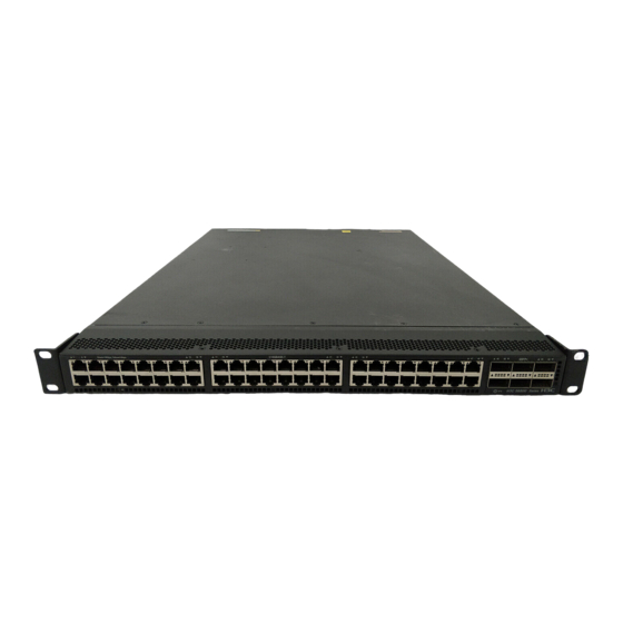
- Page 40 Chassis views S6826-48Y8C Figure2-1 Front panel (1) SFP28 port (2) SFP28 port LED (3) QSFP28 port (4) QSFP28 port LED Figure2-2 Rear panel (1) Mini USB console port (2) Copper management Ethernet port (3) Serial console port (4) USB port (5) SFP port (6) SFP port LED (7) Fan tray 1...
-
Page 41: S9826-32C
The S6826-48Y8C switch comes with a dust plug in each fiber Ethernet port. To use a fiber Ethernet port, first remove the dust plug. In Figure2-1, the dust plugs have been removed from the fiber Ethernet ports. Figure2-3 Left panel (1) Primary grounding point (2) Auxiliary grounding point S9826-32C... - Page 42 (15) Copper management Ethernet port LED (ACT) (16) System status LED (SYS) (17) Copper management Ethernet port LED (LINK) The S9826-32C switch comes with power supply slot PWR1 empty and power supply slot PWR2 installed with a filler panel. You can install one or two power supplies for the switch as needed. In Figure2-5, two LSVM1AC650 power supplies are installed in the power supply slots.
-
Page 43: Removable Components
LSVM1AC650 For more information to 63 Hz about the power • Max output power: 650 W supplies, see H3C • Melting current of the fuse: 10 A/250 V LSVM1AC650 & • LSVM1DC650 Power Rated input voltage: –40 VDC to –60 VDC Modules User Manual. -
Page 44: Fan Trays
Max airflow 35 CFM port side) • Input voltage 12 V LSWM1FANSAB (from the port side Maximum power consumption 30 W to the power supply side) H3C LSWM1FANSA & LSWM1FANSAB Fan Documentation reference Tray User Guide... -
Page 45: Ports And Leds
As a best practice, use H3C transceiver modules and cables for the switch. H3C transceiver modules and cables are subject to change over time. For the most up-to-date list of H3C transceiver modules and cables, contact H3C Support or marketing staff. For information about the specifications and views of H3C transceiver modules and cables, see H3C Transceiver Modules User Guide. -
Page 46: Usb Port
2.0. NOTE: USB devices from different vendors vary in compatibilities and drivers. H3C does not guarantee correct operation of USB devices from other vendors on the switch. If a USB device fails to operate on the switch, replace it with one from another vendor. - Page 47 10-GE SFP+ Central Modal Fiber type and Connector transceiver wavelength bandwidth transmission diameter (µm) module (nm) (MHz × km) distance 66 m (216.54 ft) 33 m (108.27 ft) Multi-mode, 62.5/125 26 m (85.30 ft) SFP-XG-LX-S Single-mode, 10 km (6.21 1310 M1310 9/125 miles)
-
Page 48: Qsfp28 Port
GE SFP Central Cable/Fiber Modal transceiver wavelength Connector type and bandwidth transmission module (nm) diameter (µm) (MHz × km) distance 50/125 Multi-mode, 550 m (1804.46 ft) 62.5/125 SFP-GE-LX-S Single-mode, 1310 10 km (6.21 miles) M1310-D 9/125 SFP-GE-LH40 -SM1310 Single-mode, 40 km (24.86 1310 9/125 miles) - Page 49 Table4-8 QSFP28 transceiver modules available for the QSFP28 ports QSFP28 Central Modal Maximum Fiber type and transceiver wavelength Connector bandwidth transmission diameter (µm) module (nm) (MHz*km) distance QSFP-100G- 2000 70 m (229.66 ft) SR4-MM850 MPO (PC Multi-mode, polished, QSFP-100G- 50/125 4700 100 m (328.08 ft) 12-fiber)
- Page 50 QSFP28 copper cable Cable length QSFP-100G-D-CAB-3M 3 m (9.84 ft) QSFP-100G-D-CAB-5M 5 m (16.40 ft) Table4-10 QSFP28 fiber cables available for the QSFP28 ports QSFP28 fiber cable Cable length QSFP-100G-D-AOC-7M 7 m (22.97 ft) QSFP-100G-D-AOC-10M 10 m (32.81 ft) QSFP-100G-D-AOC-20M 20 m (65.62 ft) Table4-11 QSFP28 to SFP28 copper cables available for the QSFP28 ports QSFP28 to SFP28 copper cable...
-
Page 51: Sfp28 Port
QSFP+ Central Fiber type Modal transceiver wavelength Connector and diameter bandwidth transmission module (nm) (µm) (MHz × km) distance • 1331 Table4-13 QSFP+ copper cables available for the QSFP+ and QSFP28 ports QSFP+ copper cable Max transmission distance LSWM1QSTK0 1 m (3.28 ft) LSWM1QSTK1 3 m (9.84 ft) LSWM1QSTK2... - Page 52 100 m (328.08 ft) NOTE: For more information about FEC negotiation, see Ethernet interface configuration in H3C S6826 & S9826 Switch Series Layer 2 –LAN Switching Configuration Guide. Table4-17 25G SFP28 copper cables available for the SFP28 ports 25G SFP28 copper cable...
-
Page 53: Leds
LEDs System status LED The system status LED shows the operating status of the switch. Table4-19 System status LED description LED mark Status Description Steady green The switch is operating correctly. Flashing green The switch is performing power-on self test (POST). Steady red The system has failed to pass POST or has problems such as fan failure. -
Page 54: Sfp+ Port Led
SFP+ port LED Each SFP+ port has a status LED to show port operating status and activities. Table4-22 SFP+ port LED description LED status Description A transceiver module or cable has been correctly installed. The port has a link and Steady green is operating at 10 Gbps. -
Page 55: Fan Tray Alarm Leds
LED mark Status Description Steady green The port is operating at 1000 Mbps. Flashing green The port is receiving or sending data at 1000 Mbps. Steady yellow The port is operating at 100 Mbps. Flashing yellow The port is receiving or sending data at 100 Mbps. Fan tray alarm LEDs The LSWM1FANSA and LSWM1FANSAB fan trays each provide an alarm LED. -
Page 56: Cooling System
Cooling system CAUTION: The chassis and power supplies use separate air aisles. Make sure the two aisles are not blocked when the switch is operating. To dissipate heat timely and ensure system stability, the switch uses the front-rear air aisle cooling system. - Page 57 Figure5-3 Airflow from the power supply side to the port side through the S6826-48Y8C chassis (with LSWM1FANSA fan trays) Figure5-4 Airflow from the port side to the power supply side through the S6826-48Y8C chassis (with LSWM1FANSAB fan trays)
Need help?
Do you have a question about the S6826 Series and is the answer not in the manual?
Questions and answers