Table of Contents
Advertisement
Quick Links
Contents
1 Preparing for installation ·········································································· 1-1
Safety recommendations ································································································································ 1-1
Examining the installation site ························································································································· 1-1
Installation tools ·············································································································································· 1-1
2 Installing the switch ·················································································· 2-2
Installation flowchart········································································································································ 2-2
Installing the switch in a liquid-cooled rack ····································································································· 2-3
Rack-mounting procedures at a glance ·································································································· 2-3
Rack-mounting requirements ·················································································································· 2-3
Installation accessories ··························································································································· 2-4
Mounting brackets, chassis rails, and grounding cable installation positions ········································· 2-6
Attaching the mounting brackets and chassis rails to the chassis ·························································· 2-6
Connecting the grounding cable to the chassis ······················································································ 2-9
Attaching the slide rails to the rack ······································································································· 2-10
Mounting the switch in the rack ············································································································· 2-11
Grounding the switch ···································································································································· 2-12
Installing/removing fan trays ························································································································· 2-13
Installing a fan tray ································································································································ 2-14
Removing a fan tray ······························································································································ 2-14
Installing/removing power modules ··············································································································· 2-15
Safety guidelines ··································································································································· 2-15
Installing a power module ····················································································································· 2-16
Removing a power module ··················································································································· 2-17
Connecting/disconnecting liquid-cooled pipes ······························································································ 2-18
Connecting liquid-cooled pipes ············································································································· 2-18
Disconnecting liquid-cooled pipes ········································································································· 2-21
Connecting the power cords ························································································································· 2-23
Verifying the installation ································································································································ 2-24
3 Accessing the switch for the first time ···················································· 3-25
Connecting the switch to a configuration terminal························································································· 3-25
Connecting the console cable ······················································································································· 3-26
Connecting a DB9-to-RJ45 console cable ···························································································· 3-26
Connecting a USB-to-RJ45 console cable ···························································································· 3-27
Setting terminal parameters ·························································································································· 3-29
Powering on the switch ································································································································· 3-29
4 Setting up an IRF fabric ········································································· 4-30
IRF fabric setup flowchart ····························································································································· 4-30
Planning IRF fabric setup ······························································································································ 4-31
Planning IRF fabric size and the installation site ··················································································· 4-31
Identifying the master switch and planning IRF member IDs ································································ 4-31
Planning IRF topology and connections································································································ 4-32
Identifying physical IRF ports on the member switches ········································································ 4-33
Planning the cabling scheme ················································································································ 4-33
Configuring basic IRF settings ······················································································································ 4-35
Connecting the physical IRF ports ················································································································ 4-35
Accessing the IRF fabric to verify the configuration ······················································································ 4-35
5 Setting up an M-LAG system ··································································· 5-1
M-LAG system setup flowchart ······················································································································· 5-1
Planning for setting up an M-LAG system······································································································· 5-2
Determining device installation locations ································································································ 5-2
Reserving physical ports for M-LAG connection ····················································································· 5-2
Planning the cable connection scheme ··································································································· 5-3
Configuring the M-LAG system settings ·································································································· 5-4
i
Advertisement
Table of Contents

Related Manuals for H3C S6850-56HF-CP


Summary of Contents for H3C S6850-56HF-CP
-
Page 1: Table Of Contents
Contents 1 Preparing for installation ·········································································· 1-1 Safety recommendations ································································································································ 1-1 Examining the installation site ························································································································· 1-1 Installation tools ·············································································································································· 1-1 2 Installing the switch ·················································································· 2-2 Installation flowchart········································································································································ 2-2 Installing the switch in a liquid-cooled rack ····································································································· 2-3 Rack-mounting procedures at a glance ·································································································· 2-3 Rack-mounting requirements ··················································································································... - Page 2 Restrictions and guidelines ····················································································································· 5-4 Connecting the M-LAG member switches ······························································································· 5-5 Verifying the configuration······························································································································· 5-5 6 Maintenance and troubleshooting ···························································· 6-1 Power module failure ······································································································································ 6-1 Symptom ················································································································································· 6-1 Solution ··················································································································································· 6-1 Fan tray failure ················································································································································ 6-1 Symptom ················································································································································· 6-1 Solution ···················································································································································...
-
Page 3: Preparing For Installation
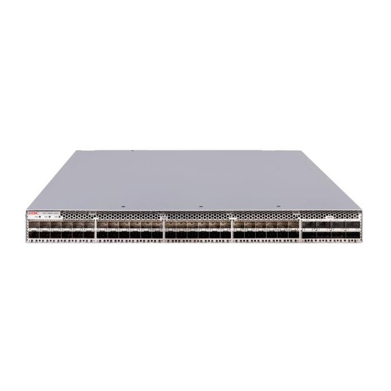
Preparing for installation This document is applicable to the H3C S6850-56HF-CP cold plate-based liquid-cooled Ethernet switch (product code LS-6850-56HF-CP). Safety recommendations To avoid bodily injury or damage to the switch, read the following safety recommendations carefully before working with the switch. Note that the recommendations do not cover every possible hazardous condition. -
Page 4: Installing The Switch
Installing the switch CAUTION: Keep the tamper-proof seal on a mounting screw on the chassis cover intact, and if you want to open the chassis, contact H3C for permission. Otherwise, H3C shall not be liable for any consequence caused thereby. Installation flowchart... -
Page 5: Installing The Switch In A Liquid-Cooled Rack
Figure2-4 LS-6850-56HF-CP chassis dimensions (mounting brackets installed at the power module side) (1) Power module handle (2) Mounting bracket NOTE: For more information about the liquid-cooled rack, see H3C Cold Plate-Based Liquid-Cooling System User Guide. Table2-1 Distance requirements between the front and rear rack posts Distance between the Installation... -
Page 6: Installation Accessories
(provided). See hole in the narrow flange supports Figure2-8. hanging a fixed asset tag. S6850-56HF-CP 1U high, including one pair of long slide rails and 1U high, one pair. See Figure2-6. one pair of chassis rails (provided). See The mounting bracket with a Figure2-7. - Page 7 Figure2-5 Extended mounting brackets Figure2-6 1U mounting brackets Figure2-7 1U long slide rail and chassis rail (1) Chassis rail (2) Long slide rail Figure2-8 1U short slide rail and chassis rail (1) Chassis rail (2) Short slide rail...
-
Page 8: Mounting Brackets, Chassis Rails, And Grounding Cable Installation Positions
Figure2-9 1U super-short slide rail and chassis rail (1) Chassis rail (2) Super-short slide rail Mounting brackets, chassis rails, and grounding cable installation positions The LS-6850-56HF-CP switch provides two grounding points: primary grounding point (with a grounding sign) and auxiliary grounding point, as shown in Figure2-10. Select installation positions for the mounting brackets, chassis rails, and grounding cable as required. - Page 9 To install the mounting brackets at the power module-side mounting position, see Figure2-15 and Figure2-16. Place the chassis rail against the chassis side panel. Align the chassis rail installation holes with the screw holes. Use the provided M4 screws to attach the chassis rail to the chassis. See Figure2-11 to Figure2-16.
- Page 10 Figure2-13 Attaching the mounting brackets and chassis rails to the LS-6850-56HF-CP switch (port-side mounting position for the mounting brackets, super-short slide rails, chassis rails not reaching out of the chassis) Figure2-14 Attaching the mounting brackets and chassis rails to the LS-6850-56HF-CP switch (port-side mounting position for the mounting brackets, super-short slide rails, chassis rails reaching out of the chassis) Figure2-15 Attaching the mounting brackets and chassis rails to the LS-6850-56HF-CP...
-
Page 11: Connecting The Grounding Cable To The Chassis
• If the grounding cable length or terminal type cannot meet your requirement, make an applicable grounding cable or contact H3C Support. • If you use a grounding point on the side panel to ground the switch, connect the grounding cable to the grounding point before installing the switch in the liquid-cooled rack. -
Page 12: Attaching The Slide Rails To The Rack
Figure2-17 Attaching a grounding cable that has a single-hole lug to the grounding point Figure2-18 Attaching a grounding cable that has a dual-hole lug to the grounding point Attaching the slide rails to the rack Identify the planned slide rail installation position in the rack. Plan a 1U rack space for installation of 1U slide rails. -
Page 13: Mounting The Switch In The Rack
Install cage nuts (user-supplied) in the mounting holes in the rack posts. Align the screw holes in one slide rail with the cage nuts in a rear rack post. Use user-supplied M6 screws to attach the slide rail to the post. See Figure2-20. As a best practice, use a torque of 30 kgf-cm (2.94 Nm) to fasten the M6 screws. -
Page 14: Grounding The Switch
Figure2-21 Mounting the S6850-56HF-CP switch in the liquid-cooled rack Grounding the switch CAUTION: • Correctly connecting the grounding cable is crucial to lightning protection and EMI protection. • Connect the grounding cable to the grounding system in the equipment room. Do not connect it to a fire main or lightning rod. -
Page 15: Installing/Removing Fan Trays
• Do not place the fan tray in a wet area, and prevent liquid from entering into the fan tray. • When an internal circuit or component of the fan tray fails, contact H3C Support. Do not remove any component from the fan tray yourself. -
Page 16: Installing A Fan Tray
H3C S6805 & S6825 & S6850 & S9850 Switch Series Fundamentals Command Reference. Select fan trays for the switch as needed. For the available fan trays and their specifications, see H3C S6850-56HF-CP Cold Plate-Based Liquid-Cooled Switch Hardware Information and Specifications. -
Page 17: Installing/Removing Power Modules
• Provide a separate circuit breaker for each power module. The S6850-56HF-CP switch comes with one power module slot empty and one installed with a filler panel. You can install power modules for the switch as required. For the available power modules and their specifications, see H3C S6850-56HF-CP Cold Plate-Based Liquid-Cooled Switch Hardware Information and Specifications. -
Page 18: Installing A Power Module
• To avoid power module damage, do not open the power module. When an internal circuit or component of the power module fails, contact H3C Support. Installing a power module CAUTION: • Follow the forward inertia of the power module when inserting it into the chassis, and make sure the power module has firm contact with the connectors on the backplane. -
Page 19: Removing A Power Module
Figure2-28 Installing a power module Removing a power module CAUTION: When the switch has power modules in 1+1 redundancy mode, removing one power module does not affect the operation of the switch. When the switch has only one power module installed, removing the power module powers off the switch. -
Page 20: Connecting/Disconnecting Liquid-Cooled Pipes
(with a red mark). Hold the shell of the female quick connector (as shown by callout 1) and push it into the male quick connector until it clicks into place. For more information about the manifold, see H3C Cold Plate-Based Liquid-Cooling System User Guide. - Page 21 Figure2-31 Connecting a quick connector on the red water outlet pipe to the manifold Figure2-32 Connected a quick connector on the red water outlet pipe to the manifold As shown in Figure2-33, use the same method to connect a quick connector on the blue water inlet pipe to the manifold.
- Page 22 Figure2-33 Connecting a quick connector on the blue water inlet pipe to the manifold As shown in Figure2-34, orient the other female quick connector on the blue water inlet pipe with the IN male connector on the switch cold plate. Hold the shell of the female quick connector (as shown by callout 1) and push it into the IN male connector until it clicks into place.
-
Page 23: Disconnecting Liquid-Cooled Pipes
Figure2-35 Connected a quick connector on the blue water inlet pipe to the switch cold plate As shown in Figure2-36, use the same method to connect the other quick connector on the red water outlet pipe to the switch cold plate. Orient the female quick connector on the pipe with the OUT male connector on the switch cold plate. - Page 24 As shown in Figure2-37, hold and pull the shell of the female quick connector (as shown by callout 1) on the blue water inlet pipe to release the female quick connector. Then, disconnect the female quick connector from the manifold. Figure2-37 Disconnecting the female quick connector on the blue water inlet pipe from the manifold Use the same method to disconnect the female quick connector on the red water outlet pipe...
-
Page 25: Connecting The Power Cords
Figure2-39 Disconnecting the female quick connector on the blue water inlet pipe from the switch Figure2-40 Disconnecting the female quick connector on the red water outlet pipe from the switch Connecting the power cords WARNING! Provide a circuit breaker for each power input. When you connect a power cord, make sure the circuit breaker is switched off. -
Page 26: Verifying The Installation
Insert the female connector of the AC power cord supplied with the power module into the power receptacle on the power module. Use a Velcro cable strap to secure the power cord to the handle of the power module, as shown in Figure2-41. -
Page 27: Accessing The Switch For The First Time
The signal pinout for the RJ-45 connector of a serial console cable varies by vendor. To avoid abnormal configuration terminal display, use a serial console cable provided by H3C. For more information, see Table3-2. To prepare a serial console cable yourself, make sure the signal pinout for the RJ-45 connector is the same as that shown in Table3-3. -
Page 28: Connecting The Console Cable
Table3-2 Console cable views Product code for the Console cable type Console cable view recommended H3C console cable DB9-to-RJ45 console cable 04042967 USB-to-RJ45 console cable 0404A1EE Connecting the console cable Connecting a DB9-to-RJ45 console cable A serial console cable is an 8-core cable, with a crimped RJ-45 connector at one end for connecting to the serial console port of the switch, and a DB-9 female connector at the other end for connecting to the serial port on the console terminal. -
Page 29: Connecting A Usb-To-Rj45 Console Cable
Click the following link, or copy it to the address bar on your browser and download the USB-to-RJ45 console driver. http://www.h3c.com/en/home/USB_to_RJ45_Console/ View the TXT file Read me in the Windows folder to check whether the Windows system of the configuration terminal supports the driver. - Page 30 Figure3-3 Driver installation wizard Click Finish after the drive installation is completed. Figure3-4 Finishing the driver installation Connect the standard USB connector of the cable to the USB port of the configuration terminal. 3-28...
-
Page 31: Setting Terminal Parameters
After the startup completes, you can access the CLI to configure the switch. For more information about the configuration commands and CLI, see H3C S6805 & S6825 & S6850 & S9850 Switch Series Configuration Guides and H3C S6805 & S6825 & S6850 &... -
Page 32: Setting Up An Irf Fabric
Setting up an IRF fabric You can use H3C IRF technology to connect and virtualize multiple S6850-56HF-CP switches into a large virtual switch called an "IRF fabric" for flattened network topology, and high availability, scalability, and manageability. IRF fabric setup flowchart... -
Page 33: Planning Irf Fabric Setup
IRF member switches will automatically elect a master. You can affect the election result by assigning a high member priority to the intended master switch. For more information about master election, see IRF configuration in H3C S6805 & S6825 & S6850 & S9850 Switch Series Virtual Technologies Configuration Guide. -
Page 34: Planning Irf Topology And Connections
Planning IRF topology and connections You can create an IRF fabric in daisy chain topology, or more reliably, ring topology. In ring topology, the failure of one IRF link does not cause the IRF fabric to split as in daisy chain topology. Rather, the IRF fabric changes to a daisy chain topology without interrupting network services. -
Page 35: Identifying Physical Irf Ports On The Member Switches
Figure4-3 IRF fabric in ring topology You can set up IRF links between S6850-56HF-CP switches as follows: • Use a QSFP28 module and fiber or a QSFP28 cable to connect QSFP28 ports for a 100-GE IRF physical connection. • Use a QSFP+ module and fiber or a QSFP+ cable to connect QSFP28 ports for a 40-GE IRF physical connection. - Page 36 The following subsections describe several IRF connection schemes by using the QSFP28 cables and QSFP28 transceiver modules and fibers. As a best practice, use the ring topology for IRF connections. Connecting the IRF member switches in one rack Figure4-4 shows an example for connecting four IRF member switches in a rack. The switches in the ring topology (see Figure4-5) are in the same order as connected in the rack.
-
Page 37: Configuring Basic Irf Settings
Execute the command to verify the basic IRF settings. display irf configuration For more information about configuring basic IRF settings, see H3C S6805 & S6825 & S6850 & S9850 Switch Series Virtual Technologies Configuration Guide. Connecting the physical IRF ports CAUTION: Wear an ESD wrist strap when you install transceiver modules, fibers, and cables. - Page 38 To avoid IP address collision and network problems, configure at least one multi-active detection (MAD) mechanism to detect the presence of multiple identical IRF fabrics and handle collisions. For more information about MAD detection, see H3C S6805 & S6825 & S6850 & S9850 Switch Series Virtual Technologies Configuration Guide.
-
Page 39: Setting Up An M-Lag System
The two sets of commands are consistent in the service configuration methods, functions, and output, with only differences in the command keywords. For the differences in the command keywords, see M-LAG configuration in Layer 2—LAN Switching Configuration Guide of H3C S6805 & S6825 & S6850 & S9850 Switch Series Configuration Guides-Release 671x. -
Page 40: Planning For Setting Up An M-Lag System
Power on the switches. For detailed information about M-LAG, see M-LAG configuration in Configure the M-LAG system H3C S6805 & S6825 & S6850 & S9850 Switch Series Layer settings. 2—LAN Switching Configuration Guide. Select cables or transceiver modules and optical fibers matching Connect the member switches. -
Page 41: Planning The Cable Connection Scheme
Transceiver modules and optical fibers can be combined flexibly and is suitable for longer distance connections. For information about the transceiver modules and cables supported by the switch, see H3C S6850-56HF-CP Cold Plate-Based Liquid-Cooled Switch Hardware Information and Specifications. -
Page 42: Configuring The M-Lag System Settings
Peer-link interface settings. • Keepalive parameters. For information about logging in to the switch, see H3C S6805 & S6825 & S6850 & S9850 Switch Series Fundamentals Configuration Guide. For information about configuring the M-LAG system settings, see M-LAG configuration in H3C S6805 &... -
Page 43: Connecting The M-Lag Member Switches
Create a Layer 3 interface on a member device, assign it an IP address, and make sure the device and the remote network management station can reach each other. Use Telnet or SNMP to access the device remotely. For more information, see H3C S6805 & S6825 & S6850 & S9850 Switch Series Fundamentals Configuration Guide. -
Page 44: Maintenance And Troubleshooting
Power module failure Symptom The power module status LED on the power module is not steady green. For more information about the LED on a power module, see H3C S6850-56HF-CP Cold Plate-Based Liquid-Cooled Switch Hardware Information and Specifications. Solution Verify that the power cord is connectedly correctly. -
Page 45: Garbled Display On The Configuration Terminal
Verify that the console cable is connected correctly. Verify that the console cable is in good condition. Verify that the terminal settings are correct. If the issue persists, contact H3C Support. Garbled display on the configuration terminal Symptom The configuration terminal displays garbled texts.
Need help?
Do you have a question about the S6850-56HF-CP and is the answer not in the manual?
Questions and answers