Advertisement
Service Facts
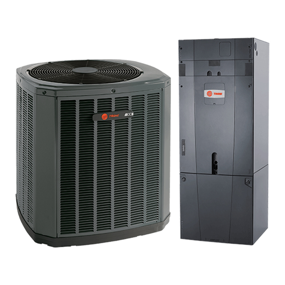
Convertible Air Handlers
Models: Series 5 Air Handlers 1-1/2 to 5 Ton
Black Epoxy Coil
GAM5B0A18M11EA
GAM5B0A24M21EA
GAM5B0B30M21EA
GAM5B0B36M31EA
GAM5B0C42M31EA
GAM5B0C48M41EA
GAM5B0C60M51EA
*For use with BAYEA series heaters ONLY
WARNING:
IMPORTANT --- This document contains a wiring diagram and service information. This is customer property and is to remain with this
unit. Please return to service information pack upon completion of work.
!
SAFETY HAZARD!
use by individuals possessing adequate backgrounds
of electrical and mechanical experience. Any attempt to
repair a central air conditioning product may result in
personal injury and/or property damage. The manufac-
ture or seller cannot be responsible for the interpreta-
tion of this information, nor can it assume any liability
in connection with its use.
!
LIVE ELECTRICAL COMPONENTS!
stallation, testing, servicing, and troubleshooting of this
product, it may be necessary to work with live electrical
components. Failure to follow all electrical safety pre-
cautions when exposed to live electrical components
could result in death or serious injury.
Important: Panel damage can occur with prolonged
exposure to POE lubricants. Air handler front panels
that come in contact with POE oil must be washed
immediately with soapy water.
Table of Contents
Product Specifications ....................................................................................................................................2
Airflow Performance........................................................................................................................................3
Heater Attribute Data.....................................................................................................................................10
Wiring Diagram..............................................................................................................................................14
Sequence of Operation..................................................................................................................................15
Subcooling Adjustment....................................................................................................................................16
Troubleshooting.............................................................................................................................................19
Standard Coil
GAM5B0A18M11SB
GAM5B0A24M21SB
GAM5B0B30M21SB
GAM5B0B36M31SB
GAM5B0C42M31SB
GAM5B0C48M41SB
GAM5B0C60M51SB
HAZARDOUS VOLTAGE - DISCONNECT POWER BEFORE SERVICING
WARNING
This information is intended for
WARNING
During in-
GAM5-SF-1P-EN
!
PRESSURIZED REFRIGERANT!
TAINS OIL AND REFRIGERANT UNDER HIGH PRES-
SURE. RECOVER REFRIGERANT TO RELIEVE PRES-
SURE BEFORE OPENING THE SYSTEM.
DO NOT USE NON-APPROVED REFRIGERANTS OR
REFRIGERANT SUBSTITUTES OR REFRIGERANT AD-
DITIVES.
!
This product can expose you to chemicals including
lead, which are known to the State of California to case
cancer and birth defects or other reproductive harm.
For more information go to www. P65Warnings.ca.gov
Note: This unit is certified to UL 1995.
The interior cabinet wall meets the following:
- UL94-5VA Flame Class Listed
- UL723 Steiner Tunnel Listed for 25/50 Flame/
Smoke
- UL746C Listed for Exposure to Ultraviolet Light,
Water Exposure and Immersion
WARNING
SYSTEM CON-
WARNING
Advertisement

Related Manuals for Trane 5 Series


Summary of Contents for Trane 5 Series
-
Page 1: Table Of Contents
Service Facts GAM5-SF-1P-EN Convertible Air Handlers Models: Series 5 Air Handlers 1-1/2 to 5 Ton Black Epoxy Coil Standard Coil GAM5B0A18M11EA GAM5B0A18M11SB GAM5B0A24M21EA GAM5B0A24M21SB GAM5B0B30M21EA GAM5B0B30M21SB GAM5B0B36M31EA GAM5B0B36M31SB GAM5B0C42M31EA GAM5B0C42M31SB GAM5B0C48M41EA GAM5B0C48M41SB GAM5B0C60M51EA GAM5B0C60M51SB *For use with BAYEA series heaters ONLY WARNING: HAZARDOUS VOLTAGE - DISCONNECT POWER BEFORE SERVICING IMPORTANT --- This document contains a wiring diagram and service information. -
Page 2: Product Specifications
PRODUCT SPECIFICATIONS GAM5B0B36M31SB GAM5B0A18M11SB GAM5B0A24M21SB GAM5B0B30M21SB MODEL GAM5B0B36M31EA GAM5B0A18M11EA GAM5B0A24M21EA GAM5B0B30M21EA 208-230/1/60 RATED VOLTS/PH/HZ. 208-230/1/60 208-230/1/60 208-230/1/60 See O.D. Specifications RATINGS ① See O.D. Specifications See O.D. Specifications See O.D. Specifications Plate Fin Plate Fin Plate Fin INDOOR COIL — Type Plate Fin 3 - 14 3 - 14... -
Page 3: Airflow Performance
AIRFLOW PERFORMANCE GAM5B0A18M11SB, GAM5B0A18M11EA EXTERNAL STATIC AIRFLOW (CFM) (in w.g) Speed Taps - 230 VOLTS Speed Taps - 208 VOLTS 4 † 4 † 1081 1078 1044 1038 NOTES: 1. Values are with wet coil and without filters. 2. Contact your particular filter manufacturer for pressure drop data. 3. - Page 4 AIRFLOW PERFORMANCE GAM5B0A24M21SB, GAM5B0A24M21EA EXTERNAL STATIC AIRFLOW (CFM) (in w.g) Speed Taps - 230 VOLTS Speed Taps - 208 VOLTS 4 † 4 † 1081 1078 1044 1038 NOTES: 1. Values are with wet coil and without filters. 2. Contact your particular filter manufacturer for pressure drop data. 3.
- Page 5 AIRFLOW PERFORMANCE GAM5B0B30M21SB, GAM5B0B30M21EA EXTERNAL STATIC AIRFLOW (CFM) (in w.g) Speed Taps - 230 VOLTS Speed Taps - 208 VOLTS 4 † 4 † 1282 1150 1279 1146 1238 1094 1232 1088 1186 1047 1177 1039 1141 1130 1091 1076 1033 1016 NOTES:...
- Page 6 AIRFLOW PERFORMANCE GAM5B0B36M31SB, GAM5B0B36M31EA EXTERNAL STATIC AIRFLOW (CFM) (in w.g) Speed Taps - 230 VOLTS Speed Taps - 208 VOLTS 4 † 4 † 1438 1387 1197 1013 1435 1383 1194 1009 1394 1340 1143 1388 1334 1137 1350 1299 1090 1341 1291...
- Page 7 AIRFLOW PERFORMANCE GAM5B0C42M31SB, GAM5B0C42M31EA EXTERNAL STATIC AIRFLOW (CFM) (in w.g) Speed Taps - 230 VOLTS Speed Taps - 208 VOLTS 4 † 4 † 1644 1575 1401 1266 1641 1572 1398 1263 1596 1525 1346 1215 1590 1519 1340 1209 1550 1480 1300...
- Page 8 AIRFLOW PERFORMANCE GAM5B0C48M41SB, GAM5B0C48M41EA EXTERNAL STATIC AIRFLOW (CFM) (in w.g) Speed Taps - 230 VOLTS Speed Taps - 208 VOLTS 4 † 4 † 1913 1770 1694 1593 1910 1767 1691 1590 1874 1730 1653 1547 1868 1724 1647 1541 1834 1690 1611...
- Page 9 AIRFLOW PERFORMANCE GAM5B0C60M51SB, GAM5B0C60M51EA EXTERNAL STATIC AIRFLOW (CFM) (in w.g) Speed Taps - 230 VOLTS Speed Taps - 208 VOLTS 4 † 4 † 2327 2020 1914 1819 1125 2324 2017 1910 1816 1122 2285 1980 1873 1780 2279 1974 1867 1774 2237...
-
Page 10: Heater Attribute Data
WIRING DATA GAM5B0A18M11SB, GAM5B0A18M11EA 240 VOLT 208 VOLT Heater Heater Heater Model Minimum Maximum Minimum Maximum Capacity Capacity Amps Amps Circuits Circuit Overload Circuit Overload Ampacity Protection Ampacity Protection BTUH BTUH Circuit Circuit No Heater 2.8* 2.8* BAYEAAC04BK1 3.84 13100 16.0 2.88 9800... - Page 11 WIRING DATA GAM5B0B30M21SB, GAM5B0B30M21EA 240 VOLT 208 VOLT Heater Heater Heater Model Minimum Maximum Minimum Maximum Capacity Capacity Amps Amps Circuits Circuit Overload Circuit Overload Ampacity Protection Ampacity Protection BTUH BTUH Circuit Circuit No Heater 2.8* 2.8* BAYEAAC04BK1 3.84 13100 16.0 2.88 9800...
- Page 12 WIRING DATA GAM5B0C42M31SB, GAM5B0C42M31EA 240 VOLT 208 VOLT Heater Heater Heater Model Minimum Maximum Minimum Maximum Capacity Capacity Amps Amps Circuits Circuit Overload Circuit Overload Ampacity Protection Ampacity Protection BTUH BTUH Circuit Circuit No Heater 4.1* 4.1* BAYEAAC04BK1 3.84 13100 16.0 2.88 9800...
- Page 13 WIRING DATA GAM5B0C60M51SB, GAM5B0C60M51EA 240 VOLT 208 VOLT Heater Heater Heater Maximum Model Minimum Maximum Minimum Capacity Capacity Amps Amps Overload Circuits Circuit Overload Circuit Protec- Ampacity Protection Ampacity Circuit Circuit tion BTUH BTUH No Heater 7.6* 7.6* BAYEAAC04BK1 3.84 13100 16.0 2.88...
-
Page 14: Wiring Diagram
GAM5-SF-1P-EN... -
Page 15: Sequence Of Operation
SEQUENCE OF OPERATION FOR GAM5 AIR HANDLERS GAM5 Sequence of Operation: Single Stage Heat Pump OD (heating) Abbreviations 1. R-Y contacts close on the comfort control sending 24VAC to Y terminal on the fan relay and the Y in See unit, electric heat, and field wiring diagrams for the outdoor unit. -
Page 16: Subcooling Adjustment
SEQUENCE OF OPERATION FOR GAM5 AIR HANDLERS Electric Heating 1. R-W contacts close on the comfort control sending 24VAC to the W terminal on the fan relay. 24VAC is also sent to EHC to energize the heat relay. 2. R-G contacts close on the comfort control send- ing 24VAC to the G terminal on the fan relay. - Page 17 Adjustments for 2-Stage outdoor AC models 16 SEER Cooling Models OD MODEL ID MODEL SPEED TAP SYSTEM STAGE 4TTR6024A* 0.333 GAM5B0A24M21SB 4TTX6024G* 0.273 GAM5B0A24M21EA 4A7A6024G* 4TTR6036A* 1225 0.357 GAM5B0B36M31SB 4TTX6036G* 1070 0.272 GAM5B0B36M31EA 4A7A6036G* 4TTR6036A* 1225 0.400 GAM5B0C42M31SB 4TTX6036G* 1115 0.331 GAM5B0C42M31EA 4A7A6036G*...
- Page 18 Adjustments for 2-Stage outdoor HP models 16 SEER Heat Pump Models OD MODEL ID MODEL SPEED TAP SYSTEM STAGE 4TWR6024A*④ 0.333 GAM5B0A24M21SB 4TWX6024G*④ 0.293 GAM5B0A24M21EA 4A6H6024G*④ 4TWR6024A* 0.383 GAM5B0B30M21SB 4TWX6024G* 0.301 GAM5B0B30M21EA 4A6H6024G* 4TWR6036A* 1150 0.500 GAM5B0B36M31SB 4TWX6036E* 1005 0.382 GAM5B0B36M31EA 4A6H6036E* 4TWR6048A*...
- Page 19 Before starting, insure the blower wheel, indoor and outdoor coils are clean. Correct air Is sub cooling at the Is superheat Is air flow at least flow outdoor unit between < 5F? 350 CFM per ton? problem 8 to 12F? Is superheat TXV is OK <...
-
Page 20: Troubleshooting
Check operation About Trane and American Standard Heating and Air Conditioning Trane and American Standard create comfortable, energy efficient indoor environments for residential applications. For more information, please visit www.trane.com or www.americanstandardair.com The manufacturer has a policy of continuous data improvement and it reserves the right to change design and specifications without notice. We are committed to using environmentally conscious print practices.
Need help?
Do you have a question about the 5 Series and is the answer not in the manual?
Questions and answers