Table of Contents
Advertisement
Installer's Guide
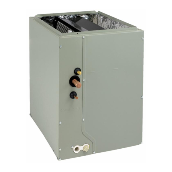
Cased Aluminum "Convertible" Coils
Models:
5TXCA001AS3HCA
5TXCA002AS3HCA
5TXCB003AS3HCA
5TXCB004AS3HCA
ALL phases of this installation must comply with NATIONAL, STATE AND LOCAL CODES
IMPORTANT — This Document is customer property and is to remain with this unit. Please return to service information pack
upon completion of work.
!
WARNING
SAFETY WARNING
Only qualified personnel should install and service the
equipment. The installation, starting up, and servicing of
heating, ventilating, and air-conditioning quipment can be
hazardous and requires specific knowledge and training.
Improperly installed, adjusted or altered equipment by an
unqualified person could result in death or serious injury.
When working on the equipment, observe all precautions
in the literatures and on the tags, stickers, and labels, and
that are attached to the equipment.
IMPORTANT: These instructions do not cover all variations in
systems nor provide for every possible contingency to be met
in connection with the installation. Should further information
be desired or should particular problems arise which are not
covered sufficiently for the purchaser's purposes, the matter
should be referrred to your installing dealer or local dsitributor.
!
WARNING
SAFETY HAZARD!
This air handler shall only be connected to an outdoor
unit suitable for use with refrigerant R-454B.
!
WARNING
SAFETY HAZARD!
This appliance is not to be used by persons (including
children) with reduced physical, sensory, or mental
capabilities, or lack of experience and knowledge,
unless they have been given supervision or instructions
concerning the use of appliance by a person
responsible for their safety.
!
WARNING
RISK OF FIRE!
Flammable refrigerant used. To be repaired only by
trained service professional. Do not puncture refrigerant
tubing. Dispose of properly in accordance with federal
or local regulations.
!
WARNING
WARNING!
This product can expose you to chemicals including
lead, which are known to the State of California to cause
cancer and birth defects or other reproductive harm. For
more information go to www. P65Warnings. ca.gov
5TXCB006AS3HCA
5TXCC005AS3HCA
5TXCC007AS3HCA
5TXCD008AS3HCA
18-AD47D1-1B-EN
5TXCC009AS3HCA
5TXCD010AS3HCA
!
WARNING
HAZARDOUS VAPORS!
Failure to follow this caution could result in property
damage or personal injury. Equipment corrosion damage.
To prevent shortening its service life, the unit should not
be used during the finishing phases of construction or
remodeling. The low return air temperatures can lead to
the formation of condensate. Condensate in the presence
of chlorides and fluorides from paint, varnish, stains,
adhesives, cleaning compounds, and cement creates a
corrosive condition which may cause rapid deterioration
of the cabinet and internal components.
!
WARNING
RISK OF FIRE!
Failure to following this warning could result in serious
injury, death, or property damage.
The following requirements apply to the room where the
cased coil is installed:
•
All combustion appliances located in the same room
that have continuous pilot lights are equipped with an
effective flame arrest.
•
Auxiliary devices which may be a potential ignition
source, such as hot surfaces or electric switching
devices, shall not be installed in the connecting ductwork
unless they have been approved by the manufacturer or
declared suitable with the refrigerant used.
•
All indoor field-made joints of the field piping have
been checked for refrigerant leaks after charging
using an electronic leak detector calibrated for R-454B
having a sensitivity of 5 grams per year or better.
•
The room is constructed to ensure that should any
refrigerant leak it will not stagnate and create a fire
hazard.
!
WARNING
PRESSURIZED REFRIGERANT!
Failure to follow this Warning could result in personal
injury.
System contains oil and refrigerant under high pressure.
Recover refrigerant to relieve pressure before opening
the system. Do not use non-approved refrigerants or
refrigerant substitutes or refrigerant additives.
Advertisement
Table of Contents
Troubleshooting

Related Manuals for Trane 5TXCB003AS3HCA


Summarization of Contents
B. APPLICATION INFORMATION
1. FURNACE AND COIL
Coil must be installed downstream (in the outlet air) of the furnace.
2. INDOOR UNIT AIRFLOW
Indoor unit must provide the required airflow for approved combinations.
C. INFORMATION ON SERVICING
Prior to Beginning Work
Safety checks for flammable refrigerants before starting work.
Repairs to Electrical Components
Guidelines for changing electrical components and performing safety checks.
Detection of Flammable Refrigerants
Acceptable methods for detecting refrigerant leaks.
Removal and Evacuation
Procedures for removing and evacuating refrigerant safely.
Charging Procedures
Requirements for charging refrigerant systems.
Recovery
Recommendations for safely removing refrigerant.
Decommissioning
Steps for safely decommissioning equipment.
D. REFRIGERANT LEAK DETECTION SYSTEM
LEAK DETECTION SYSTEM!
Description of the leak detection system and its actions.
Minimum Conditioned Space
Verifying conditioned space size for refrigerant dilution.
F. FURNACE IN UPFLOW POSITION
1. UPFLOW COIL CONVERSION
Optional steps to maximize airflow efficiency in upflow.
2. UPFLOW GAS FURNACE
Instructions for connecting coil to upflow gas furnace.
G. FURNACE IN DOWNFLOW POSITION
1. DOWNFLOW COIL CONVERSION
Optional steps to maximize airflow efficiency in downflow.
2. DOWNFLOW GASKET INSTALLATION (OPTIONAL)
Optional gasket installation for humid applications.
3. DOWNFLOW GAS FURNACE
Instructions for connecting coil to downflow gas furnace.
H. FURNACE IN HORIZONTAL RIGHT POSITION
1. HORIZONTAL RIGHT COIL CONVERSION
Optional steps to maximize airflow efficiency in horizontal right.
Connecting Coil to Furnace
Instructions for connecting the coil to the furnace in horizontal right.
I. FURNACE IN HORIZONTAL LEFT POSITION
1. HORIZONTAL LEFT COIL CONVERSION
Optional steps to maximize airflow efficiency in horizontal left.
2. HORIZONTAL LEFT (All coils)
Instructions for installing coils in horizontal left position.
J. MAXIMUM AND MINIMUM AIRFLOW SETTINGS
Minimum Airflow Settings
Table showing minimum airflow settings based on refrigerant charge.
X: TROUBLESHOOTING
Troubleshooting Indoor TXV / Cooling Mode
Flowchart for diagnosing TXV issues in cooling mode.
Need help?
Do you have a question about the 5TXCB003AS3HCA and is the answer not in the manual?
Questions and answers