Table of Contents
Advertisement
Quick Links
Reception
On arrival, inspect the unit before signing the delivery note.
Specify any damage of the unit on the delivery note, and
send a registered letter of protest to the last carrier of the
goods within 72 hours of delivery. Notify the dealer at the
same time.
The unit should be totally inspected within 7 days of
delivery. If any concealed damage is discovered, send a
registered letter of protest to the carrier within 7 days of
delivery and notify the dealer.
About this Manual
Cautions appear at appropriate places in this Installation
Manual. Your personal safety and the proper operation of
this machine require that you follow them carefully.
The Trane Company assumes no liability for installations or
servicing performed by unqualified personnel. All phases of
the installation of this air conditioning system must conform
to all national, provincial, state and local codes.
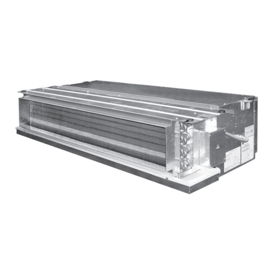
System Appearance
MCD 512-536 DB/D1
MCD 009-024 AA5
Blower
Motor
Outlet Collar
A
Evaporator Coil
Electric Heater
(Option)
Condensate Drain Pan
Note
Hanger recommendation for without return plenum model
A
Units Installation
Figure 3 (SIDE VIEW)
Table 1
A
B
C
D
DISTANCE
Min. 750 Min. 800
100
150
(MM.)
NOTE: FOR DUCT LENGTH PLEASE SEE TABLE 2, 3, 4
Figure 5
MS_SVN004_EN.indd 1
MS_SVN004_EN.indd 1
Cooling Only
Cooling Only
Cooling Heating
Cooling Heating
50 Hz Models
60 Hz Models
MCD 512 DB
MCD 512 D1
MCD 518 DB
MCD 518 D1
MCD 524 DB
MCD 524 D1
MCD 530 DB
MCD 530 D1
MCD 536 DB
MCD 536 D1
MCD 048 DB
MCD 048 D1
MCD 060 DB
MCD 060 D1
Cooling
Cooling
Cooling Heating
Cooling Heating
50Hz Models
60 Hz Models
MCDA 18 DB
MCDA 18 D1
MCDA 24 DB
MCDA 24 D1
MCDA 30 DB
MCDA 30 D1
MCDA 36 DB
MCDA 36 D1
MCDB 42 DB
MCDB 42 D1
MCDB 48 DB
MCDB 48 D1
MCDB 60 DB
MCDB 60 D1
Warranty
Warranty is based on the general terms and conditions
by country. The warranty is void if the equipment is
modified or repaired without the written approval of The
Trane Company, if the operating limits are exceeded or if
the control system or the electrical wiring is modified.
Damage due to inappropriate installation, lack of
knowledge or failure to comply with the manufacturer's
instructions, is not covered by the warranty obligation. If
the installation does not conform to the rules described in
Installation Manual, it may entail cancellation of warranty
and liabilities by The Trane Company.
Warning
Warnings are provided at appropriate places in this
manual to indicate to installers, operators and service
personnel of potentially hazardous situations which, if not
avoided, COULD result in death or serious injury.
Children should be supervised to ensure that they do not
play with the appliance.
The appliance is not to be used by persons (including
children) with reduced physical, sensory or mental
capabilities, or lack of experience and knowledge, unless
they been given supervision or instruction.
MCD 048-060 DB/D1
MCD 030-042 EB5
MCDA 18-A36 DB/D1
MCDB42-B60 DB/D1
A
Motor
Blower
B
Evaporator Coil
Return Air Plenum
Electric Heater
(Standard)
(Option)
Condensate Drain Pan
Note
Hanger recommendation for return plenum model
B
Figure 4 (TOP VIEW)
E
F
G
H
I
50
200
Min. 200 Min. 100 Min. 50 Min. 300 Min. 300
Figure 6
Model Series 5
Cooling Only
(50 Hz)
MCD 009 AA5
MCD 012 AA5
MCD 018 AA5
MCD 024 AA5
MCD 030 EB5
MCD 036 EB5
MCD 042 EB5
General Information
Introduction
This Installation Manual is given as a guide to good practice in the installation by the installer of MCD mini-split system.
Installation procedures should be performed in the sequence that they appear in this manual.
For installing the unit to operate properly and reliably, it must be installed in accordance with these instructions. Also, the
services of a qualified service technician should be employed, through the maintenance contract with a reputable service
company.
Read these installation instructions completely before installing the air conditioning system.
About the Unit
These MCD units are assembled, pressure tested, dehydrated, charged and run tested before shipment. The information
contained in this manual applies to MCD units are designed to operate in cooling mode only and in cooling or heating modes.
Important
This document is customer property and is to remain with unit. Please place in service information pack upon completion
of work. These instructions do not cover all variations in systems, nor do they provide for every possible contingency to be
met in connection with installation.
Should further information be desired or should particular problems arise which are not covered sufficiently in this manual,
the matter should be referred to your authorized Trane dealer.
Caution
Cautions are provided at appropriate places in this manual to indicate to installers, operators, and service personnel of
potentially hazardous situations which, if not avoided, MAY result in minor or moderate injury or malfunction of the unit.
Location and Preparation of Units
1. Select a convenient location that allows the air to reach every corner of the room and where it is easy to route the
refrigerant tubing, wiring and drain to the outside.
2. The ceiling construction should be strong enough to support the weight of the unit.
3. The refrigerant tubing, drain piping and wiring conduit are connected through the wall.
4. Refrigerant tubes between the indoor and the outdoor units and drain pipes should be as short as possible.
5. If a refrigerant charge adjustment is necessary, follow the Installation Manual for the Outdoor Unit.
See instructions for location and preparation of the unit in the Installation Manual for the Outdoor Unit.
Installation Method:
Indoor Unit
After selecting the location to place the unit, follow these steps:
1. Make a hole in the wall to route tubing and wiring through a locally
purchased PVC pipe.
The hole should slope downwards slightly, towards the outside
(Figure 1).
2. Before cutting, check that no pipes or studs are directly behind the place
B
to be cut.
Avoid areas where electrical wiring or conduits are located.
3. Hang the unit on a solid and level roof. Noise, vibration or leakage could
occur on and unstable foundation (Figure 3, 4). For correct installation of
duct work see (Figure 6).
4. Support the unit solidly.
5. To have access to electrical terminals, remove the right side junction box (Figure 2).
6. Note that refrigerant tubing, interconnecting wiring and drain hose should go through the wall.
Shape these items so that they will easily fit through the wall.
Outdoor Unit
See the proper installation method provided in the Installation Manual for the Outdoor Unit.
Outlet Collar
Connection of Refrigerant Tubing
Proper installation procedure is recommended in the Installation Manual Package, usually provided together with the
outdoor unit. It is advisable to read before installing.
The indoor unit refrigerant connections are located on the left hand side when facing the
unit (Figure 7).
Connecting the Units with Flaring Procedure
1. Cut the copper tube to the required length with a tube cutter.
It is recommended to cut approx. 20-30 cm. longer than the tubing length.
2. Remove burrs at the end of the copper tube with a tube reamer or file, as shown in
Figure 8.
When reaming, hold the tube end downward and be sure that no copper scraps fall into the
tube (Figure 9).
Figure 8
3. Remove the flare nut from the unit and be sure to insert on the copper tube.
4. Make a flare at the end of the copper tube with a flare tool (Figure 10).
Flare Specification
Copper diameter, In.(mm.)
1/4" (6.35)
3/8" (9.53)
1/2" (12.70)
5/8" (15.88)
3/4" (19.05)
A good flare should have the following characteristics:
• Inside surface is glossy and smooth.
• Edge is smooth.
• Tapered sides are of uniform length.
Cautions Before Connecting Tightly
1. Be sure to apply a sealing cap or water-proof tape to prevent
J
K
dust or water from getting into the tubes before they are used.
2. Be sure to apply refrigerant lubricant to the matching surfaces of the flare and union before connecting them together.
This is effective for reducing gas leaks (Figure 11).
3. For proper connection, align the union tube and flare tube straight with each other, then screw in the flare nut lightly at
first to obtain a smooth match (Figure 12).
4. Tighten the flare nuts, using the appropriate wrench.
Connecting the Unit with Brazing Prodecure
1. Cut the copper tube to the required length with a tube cutter. It is recommended to cut approx. 20-30 cm. longer than the tube
length.
2. Remove burrs at the end of the copper tube with a tube reamer (Figure 8).
3. There are 2 ways to connect the copper tube
- Use a coupling between the copper tube of Fan Coil Unit and the copper tube used for installation (Figure 13).
- Expand the copper tube by using a swaging tool set as in Figure 14.
4. To braze the copper tube, before brazing a copper tube to a solder coupling or a copper tube to an expanded tube, do
not forget to keep them tight as shown in Figure 15.
5. While welding copper tube. You should to Nitrogen flow in tube for protect soot occured.
Installation Manual
ILLUSION
Split System Concealed Type
MCD Series 50/60 Hz
Figure 1
Figure 9
H
H, (mm.)
D, (mm.)
1.0 - 2.0
8.6 - 9.7
1.0 - 3.0
12.4 - 13.9
1.0 - 2.0
15.7 - 16.1
1.0 - 3.0
19.0 - 20.3
1.0 - 3.0
22.4 - 22.7
Figure 11
MS-SVN004-EN
Figure 2
Figure 7
Figure 10
D
Figure 17
Figure 12
21-Nov-14 10:29:57
21-Nov-14 10:29:57
Advertisement
Table of Contents

Related Manuals for Trane ILLUSION MCD Series


Summary of Contents for Trane ILLUSION MCD Series
- Page 1 72 hours of delivery. Notify the dealer at the Trane Company, if the operating limits are exceeded or if of work. These instructions do not cover all variations in systems, nor do they provide for every possible contingency to be the control system or the electrical wiring is modified.
- Page 2 Trane has a policy of continuous product and product data improvement and reserves the right For more information, contact your locat district office to change design and specifications without notice.
Need help?
Do you have a question about the ILLUSION MCD Series and is the answer not in the manual?
Questions and answers