Hotsy 555 HE Service Manual
Hide thumbs
Also See for 555 HE:
- Operating instructions and parts manual (85 pages) ,
- Operating instructions and parts manual (18 pages)
Table of Contents
Advertisement
Quick Links
Advertisement
Table of Contents
Troubleshooting

Subscribe to Our Youtube Channel
Related Manuals for Hotsy 555 HE


Summary of Contents for Hotsy 555 HE
- Page 1 555 HE Service Manual 9.808-216.0 English Rev B (01/21)
-
Page 2: Table Of Contents
Unloader / bypass valve Thermal relief valve Symbols on the machine Type plate Flow pattern Overview of the appliance Callouts 555 HE 9-10 Pump overview Pump head overview Pump head cross section overview Pump breakdown overview Unloader / Bypass valve overview... - Page 3 Contents Cavitation Low pressure Replacing leaking thermal relief valve Vibration Water leaking from under pump Oil is leaking from under pump Oil is milky Pressure washer unloader cycles when trigger or spray bar trigger is released Motor will not turn on 21 –22 Machine shuts off after running a while No burner...
- Page 4 Determining if the fuel solenoid needs replacing Checking power out of the thermostat Checking power into the thermostat Check voltage into the pressure switch Checking for spark Adjusting air Technical documentation Technical specifications 555 HE Tools required 45-48 Torque specifications 9.808-216.0 English Rev B (01/21)
-
Page 5: Preface
technicians. -
Page 6: Description In This Service Manual
Safety devices serve to protect the user and must not be Observe safety information in the chapters! rendered in operational or their functions bypassed. Connection performance of appliance 20 Amp (555 HE). Pump 3 piston direct drive pump with ceramic pistons Working pressure: 1300 psi Cylinder head made of cast iron with special “HR”... -
Page 7: Safety Catch
Safety catch The safety catch on the trigger gun prevents the appli- ance from being switched on unintentionally. Unloader / bypass valve If the hand trigger bar or trigger gun is closed, the unload- The unloader / bypass valve is set by the manufacturer er / bypass valve opens and the entire water volume will and sealed. -
Page 8: Flow Pattern
4.11 Flow pattern 1 Water filter 5. Heat exchanger 2 High-pressure pump 3 Unloader valve 4 Thermal relief valve 9.808-216.0 English Rev B (01/21) -
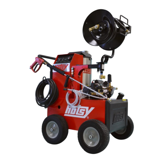
Page 9: Overview Of The Appliance
Overview of the appliance Call outs 555 HE 9.808-216.0 English Rev B (01/21) - Page 10 Trigger gun 10 Flat free tire Spray lance 11 Pump Motor switch 12 Unloader Burner switch 13 Electric motor Hour meter 14 Hose holder Adjustable thermostat 15 Fuel cap with gauge Spray nozzles 16 Fuel tank Hose reel option Power cord with GFCI 9.808-216.0 English Rev B (01/21)
-
Page 11: Pump Overview
Pump overview 5.2.1 Pump head overview 1 Outlet ports 2 Outlet / high pressure valve cover 3 Inlet ports 4 Inlet / low pressure valve cover 5 Manifold 6 Manifold bolt 5.2.2 Pump cross-section overview 1 Low pressure packing 2 High pressure packing retainer 3 Dipstick 4 Connecting rod 5 Bearing, Crankshaft... -
Page 12: Pump Breakdown Overview
5.2.3 Pump breakdown overview 1 Manifold 16 Manifold bolts 7 Inlet check valves 18 High pressure packing 9 Check valve cover 22 Low pressure packing 12 Piston 37 Sight glass 15 Outlet check valves 45 Dipstick 9.808-216.0 English Rev B (01/21) -
Page 13: Unloader / Bypass Valve Overview
Unloader / Bypass valve overview 1 Knob, adjustment, by-pass pressure 2 Spring, pressure 3 Nut, lock 4 Piston, stem 5 Piston 6 By-pass port 7 Inlet port 8 Outlet port Thermal relief valve overview 1 Inlet port 2 Thermal plate 3 Outlet directional elbow The thermal relief valve protects the pump from damaging heat build-up while the unit is in bypass mode. -
Page 14: Fuel Pump
Fuel pump 1 Inlet line from fuel tank 2 Fuel filter 3 Fuel pump 4 Fuel nozzle 5 Solenoid valve 6 Adjusting screw 7 Return line to fuel tank High-efficiency burner 1 Inlet from pump 2 Double-walled boiler cover 3 Outer heating coil 4 Inner heating coil 5 Exhaust gas flue 6 Fuel nozzle... -
Page 15: Fuel Nozzle
Fuel nozzle 3 Angle of spray In order to achieve optimum burner performance, the follow- ing factors must be exactly matched to one another: Fuel pressure Vaporization of the fuel Air Volume Combustion chamber 1 Micro-filter Exhaust gas venting 2 Thread Burner head assembly 1 Ignition electrodes 2 Burner cover... -
Page 16: Service Group
Service group Scheduled maintenance chart MAINTENANCE ITEM ACTION TIME FRAME REFERENCE SECTION Inspect Oil level daily 6.4.1 PUMP OIL After first 25 hours, then eve- Change ry 300 hours or every 3 6.4.2 months HIGH PRESSURE NOZZLE(S) Change 6 months Not shown QUICK CONNECTS/O-RINGS Change... -
Page 17: Trouble Shooting Chart
Trouble shooting chart Troubleshooting is defined as a systematic ap- proach to problem solving. Gathering infor- mation on the problem issue and eliminating what works in the system to narrow down to what doesn’t work. COMPONENT AREA PROBLEM TROUBLESHOOTING REFERENCE SECTION Understanding the difference between low, cavitation and pulsating 6.3.1 pressure... -
Page 18: Trouble Shooting Process
Trouble shooting process 6.3.1 Understanding the difference between low, cavitation and pulsating pressure Pulsation is the feeling in your hand when holding the trigger Figure 2 represents a pulsation in a pressure washer stream. gun and/or wand that feels like a water pick. It is caused by an interruption in the high pressure stream. -
Page 19: Cavitation
6.3.3 Cavitation 1. Inspect the inlet screen for debris, function and condition. Remove thermal protector and plug plumbing where ther- See section 6.5.3. If inlet screen is good, continue to #2. mal protection was (only for testing purposes). See section 6.5.4. -
Page 20: Vibration
6.3.6 Vibration 1. Inspect for cavitation. See section 6.3.3. If cavitation is Call Technical support for further instruction. not the issue, continue to #2. 6.3.7 Water leaking from under pump 1. Remove the pump manifold and inspect system. See sec- Call Technical support for further instruction. -
Page 21: Pressure Washer Unloader Cycles When Trigger Or Spray Bar Trigger Is Released
6.3.10 Pressure washer unloader cycles when trigger is released If the pressure trapped on the outlet side of the unloader is Inspect the trigger gun for leaks. See section 6.5.15. If released, the unloader will think the trigger has been pulled there not any leaks or the repairs didn’t solve the issue, and will come out of bypass. -
Page 22: Machine Shuts Off After Running A While
6.3.11 Motor will not turn on - Continued 12. With a multi meter and the wiring diagram for the ma- 14. With a multi meter and the wiring diagram for the ma- chine, test to see if you have 120 volts out of the overload chine, test to see if you have 120 volts at the motor. -
Page 23: Burner Motor Turns On But There Is No Flame-Fuel
6.3.14 Burner motor turns on but there is no flame—Fuel The burner flame with not turn on without the pressure part With a multi meter and the wiring diagram for the ma- of the machine being close to full pressure and the burner fuel chine, with the trigger pulled and the machine pressure tank full of fuel. -
Page 24: Raw Fuel Out Of Burner Exhaust
6.3.14 Burner motor turns on but there is no flame—Fuel continued 11. With a multi meter and the wiring diagram for the ma- problem but still do not have 120 volts into the pressure chine and with the trigger pulled and the machine pres- switch, continue to #12. -
Page 25: Scheduled Maintenance Activities
Scheduled maintenance activities 6.4.1 Inspecting pump oil Check the pump oil level daily. Dipstick Check the pump oil level when the pump is cold and on a level surface. Check the amount and condition of the oil using the dip- stick located on the top of the pump. -
Page 26: Burner Fuel Filter-Drain Water / Clean / Replace
6.4.4 Burner fuel filter— drain water / clean / replace The burner fuel filter should be cleaned / replaced as needed. 1. Open cover by first removing cover bolts with 30 Torx. Close the fuel shut off valve (#2) then remove the fuel bowl (#3). -
Page 27: Cleaning Soot Deposits From Heating Coils
6.4.6 Cleaning soot deposits from heating coils Smoke in the exhaust eventually will create a soot 8.704-625.0 build up on the heating coils, and that will cause a Pint—Red Devil whole list of problems, including difficulties with Soot Remover draft, efficiency, and carbon monoxide. As soot builds up on the coils, your fuel consumption in- creases. - Page 28 6.4.6 Cleaning soot deposits from heating coils—continued 10. With a T30 Torx, remove the 3 bolts holding the coil housing to the frame. 16. Remove the soot build up from the coil. 11. You can now remove the coil hous- 17.
-
Page 29: Fuel Nozzle Replacement
6.4.7 Fuel nozzle replacement Good atomization of the fuel is critical for a clean and efficient burn. The fuel nozzle should be changed annually or earlier if it becomes dirty or clogged. 1. With a T30 Torx, remove both bolts from the burner cover. With a 5/8 deep socket, remove the nozzle holder nut (see red arrow). -
Page 30: Trouble Shooting Activities
Trouble shooting activities 6.5.1 Check valve inspection / replacement 5. Inspect check valves, and check valve O-rings for dam- age. Replace if needed. To test the check valves, stand the valves with their seats facing upwards. Fill them with water. If a valve is leaking, the 1. -
Page 31: Inspect Packings, Ceramic Pistons And Connecting Rod Connection
6.5.2 Inspect packings, ceramic pistons and connecting rod connection 1. Using a 5 mm Allen wrench, remove the pump manifold bolts. See section 5.2.1 for part identification. 2. Remove the pump manifold. If needed, sometimes turning Remove packings from manifold. the crankshaft can supply a gap between the manifold and crankcase. -
Page 32: Inspect Inlet Screen
6.5.3 Inspect inlet screen Remove inlet screen (#12). Inspect for good seal to garden hose, debris, damage to rubber gasket and/or damage to mesh screen. Clean if needed. Replace if needed. Install inlet screen. 6.5.4 Bypass thermal protector A thermal protector can go bad and not leak water. If this hap- 2. -
Page 33: Test Pressure At Trigger Gun
6.5.5 Test pressure at trigger gun Machine should have a running pressure of 1300 psi and a spike pressure of less than 500 psi. Spike is the pressure reading on the gauge when you release the trigger minus the running pressure of the machine. Example: 1. -
Page 34: Test Pressure Before The Coil Inlet
6.5.8 Test pressure before the coil inlet Machine should have a running pressure of 1300 psi and a spike pressure of less than 500 psi. Spike is the pressure reading on the gauge when you release the trigger minus the running pressure of the machine. Example: 1. -
Page 35: Test Pressure Off The Pump (Bypassing The Unloader)
6.5.10 Test pressure off the pump (bypassing the unloader) 3. With a 15 mm open end wrench, 1. Remove the remove the elbow from the pump. unloader from the 4. Install a quick disconnect nipple pump. First, with a to the pump outlet and the garden 22 mm open end hose fittings back to the pump inlet. -
Page 36: Inspecting Side Of Pump For Oil Leak
6.5.12 Inspecting side of pump for oil leak Inspect around the sight glass (#1). If oil is leaking from the sight glass then replace the sight glass gasket and/or the sight glass. Inspect around the oil drain plug (#2). If oil is leaking from the oil drain plug then replace the oil drain plug gas- ket and/or the oil drain plug. -
Page 37: Inspecting Piston Guide Oil Seals For Oil Leak
6.5.14 Inspecting piston guide oil seals for oil leak Inspect where the piston guides come out of the crank- case. If oil is leaking out of the piston guide oil seals, drain the oil from the pump. See the first part of section 6.4.2. Remove and replace the piston guide oil seals. -
Page 38: Testing Power Supply
6.5.16 Testing power supply 1. With a multi meter (see sec- Confirm with wiring diagram and serial plate that the test- tion 7.4), check voltage at the ed voltage is correct. power supply. 6.5.17 Reset GFCI With power cord plugged into power supply and THE MACHINE TURNED OFF, push the reset button on the GFCI. -
Page 39: Check Voltage Out Of The Pump Switch
6.5.20 Check voltage out of the pump switch If cover is not open, refer to #1 and #2 of section 6.5.18. With a multi meter and the pump switch turned to the on position, check power out of the pump switch. Confirm power in location with the current wiring diagram for this piece of equipment. -
Page 40: Check Voltage Out Of The Contactor
6.5.24 Check voltage out of the contactor If cover is not open, refer to #1 and #2 of section 6.5.18. With a multi meter and the pump switch turned to the on position, check power out of the contactor into the over- load. -
Page 41: Check Voltage Out Of The Burner Switch
6.5.28 Check voltage out of the burner switch If cover is not open, refer to #1 and #2 of section 6.5.18. With a multi meter and the pump switch turned to the on position, check power out of the burner switch. Confirm power in location with the current wiring diagram for this piece of equipment. -
Page 42: Check Voltage At Fuel Solenoid
6.5.32 Check voltage at fuel solenoid 1. If cover is not open exposing fuel pump, see #1 of section 6.5.29. 2. Unplug fuel solenoid cord from solenoid. With a multi meter and the pump switch and burner switch turned to the on position, and the machine pres- sure washing at pressure, check power into the fuel sole- noid. -
Page 43: Check Voltage Into The Pressure Switch
6.5.36 Check voltage into the pressure switch 1. If cover is not open, refer to #1 and #2 of section 6.5.18. power in location with the current wiring diagram for this piece of equipment. With a multi meter and the pump switch and burner switch turned to the on po- sition, and the machine pressure washing at pres-... -
Page 44: Technical Documentation
Technical documentation Technical specifications 555 HE 1300 Voltage 120 V 1 PH 60 Hz Amperage 20 Amp Drive Direct Motor 2 hp 56C TEFC Motor RPM 1725 Pump Tri-Plex HE2126S 9.808-216.0 English Rev B (01/21) -
Page 45: Tools Required
Tools required Karcher service consumables Available on DISISplus in the Karcher special tools catalog Available on DISISplus in the catalog chapter “Catalogue” chapter “Catalogue” Pressure test gauge, 5000 psi, 8.904-559.0 O-ring pick 8.707-467.0 hot water Mechanical RPM gauge 6.491-361.0 Torque wrench 6.815-900.0 9.808-216.0 English Rev B (01/21) - Page 46 Safety goggle set 6.025-488.0 Hearing protection 6.025-513.0 Multimeter 6.681-037.0 or equivalent Racor Filter Funnel 8.709-955.0 Seal Pusher, HP Seal Insertion 660263, 660264, 660265 Fuel Pressure Test Gauge 8.710-276.0 500 PSI Gauge tool, LP Seal Insertion tool (supplier part no.) 8.705-364.0 Coupling 8.918-180.0 Hose 16”...
- Page 47 Packing Extractor Tool 8.712-522.0 Packing Extractor Socket 8.712-526.0 Smoke Tester 8.712-507.0 Pocket Reference Guide 8.712-505.0 Filter paper 8.712-506.0 Hotsy Touch-Up Paint 8.720-519.0 Hotsy Pump Oil 8.923-422.0 9.808-216.0 English Rev B (01/21)
- Page 48 Anti-Seize Compound 8.704-638.0 Blister pack 8.704-641.0 8 oz. can 9.808-216.0 English Rev B (01/21)
-
Page 49: Torque Specifications
Torque specifications PART NUMBER TORQUE SPECIFICATION 8.759-086.0 8.9 Ft.-Lbs. 8.759-087.0 8.9 Ft.-Lbs. Pump covers screw M6X14 7.4 Ft.-Lbs. Pump crankcase-flange, screw M6x18 7.3 Ft.-Lbs. Pump plunger bolt, M5x55 4.4 Ft.-Lbs. Pump oil drain plug, 3/8”x9 14.8 Ft.-Lbs. 9.802-741.0 6.7 N-m (max) 9.802-720.0 32 N-m 8.757-549.0... - Page 50 This page was intentionally left blank 9.808-216.0 English Rev B (01/21)
Need help?
Do you have a question about the 555 HE and is the answer not in the manual?
Questions and answers