
Related Manuals for Leadshine 3DM883


Summary of Contents for Leadshine 3DM883
- Page 1 3DM883 3-Phase Digital Stepper Drive User Manual User Manual 3DM883 Digital 3-Phase Microstep Drive Revision 1.0 ©2020 Leadshine Technology Co., Ltd.
- Page 2 Strictly adhere to the technical information regarding installation requirements. This manual is not for use or disclosure outside of Leadshine except under permission. All rights are reserved. No part of this manual shall be reproduced, stored in retrieval form, or transmitted by any means, electronic, mechanical, photocopying, recording, or otherwise without approval from Leadshine.
-
Page 3: Table Of Contents
3DM883 3-Phase Digital Stepper Drive User Manual Table of Contents 1. Introduction ......................................1 1.1 Features ...................................... 1 1.2 Applications ....................................1 2.Specifications ....................................... 1 2.1 Electrical Specifications ................................1 2.2 Environment ....................................2 2.3 Mechanical Specifications .................................2 2.4 Elimination of Heat ................................... 2 3. -
Page 4: Introduction
3DM883 3-Phase Digital Stepper Drive User Manual 1. Introduction The 3DM883 is Leadshine newest digital stepper drive based on an advanced control algorithm. It brings a unique level of system smoothness, providing optimum torque and nulls mid-range instability. Motor self-test and parameter auto-setup technology offers optimum responses with different motors and easy-to-use. -
Page 5: Environment
3DM883 3-Phase Digital Stepper Drive User Manual 2.2 Environment Cooling Natural Cooling or Forced cooling Avoid dust, oil fog and corrosive gases Environment 0 - 65°C (32 - 149°F) Ambient Temperature 40 - 90%RH Operating Environment Humidity 0 - 50°C (32 - 122°F) Operating Temperature 10-50Hz / 0.15mm... -
Page 6: Connection Pin Assignments And Led Indication
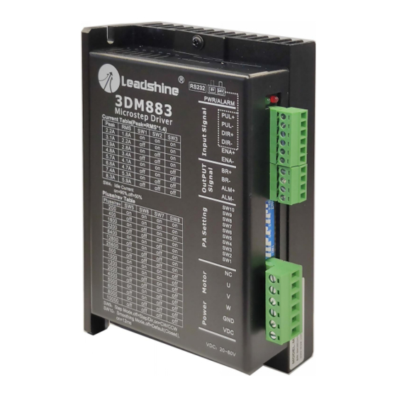
Figure 2 Connectors, DIP switches, and LED locations The 3DM883 has 4 connectors P1, P2, P3 and P4, 2 DIP switches S1and S2. P1 is for control signal connections, P2 is for fault and brake outputs, P3 is for power and motor connection, P4 is for fine tuning. -
Page 7: P3 - Motor And Power Supply Connector
20-74VDC, considering voltage fluctuation and EMF voltage. 3.4 P4 - Tuning Port 3DM883 has a tuning port with RS232 to modify the drive parameters, it’s only for tuning, not for equipment control because neither precision nor stability is sufficient. The interface definition is as follows: Figure 3 Tuning Port 3.5 Status LED (Protection Functions) -
Page 8: Control Signal And Fault Output Wiring
When over voltage or over current protection happens, 3DM883 red status LED light will blink and the impedance state between ALM+ and ALM- will change (from low to high or high to low depending on configuration) and can thus be detected. Fault output connection is optional, and it can be connected either in sinking or sourcing. -
Page 9: Sequence Chart Of Control Signals
3DM883 3-Phase Digital Stepper Drive User Manual Figure 6 Fault output connections Brake Control This signal can be used for automatic brake control while system power failure. When use a 24V electromagnetic relay, it is recommended to connect a diode (such as IN4007) in parallel, the polarity should not be reversed. -
Page 10: Typical Connection
DIP Switch Configurations The 3DM883 has one 10-bit DIP switch and one 1-bit selector. The first 10-bit is used to configure settings of micro step resolution, output current, motor standstill current, pulse type and smoothing time as shown below. -
Page 11: Microstep Resolution Configurations
3DM883 3-Phase Digital Stepper Drive User Manual 5.1 Microstep Resolution Configurations Microstep resolution is set by SW5, 6, 7, 8 of the DIP switches as shown in the following table, default means can be set by Leadshine ProTuner Microstep Steps/rev.(for 1.8°motor) -
Page 12: Idle Current Configuration
SW10. Setting to ON to activate the feature with 12ms acceleration time. 5.5 Automatic Motor Matching & Self Configuration When powered on a 3DM883 will automatically configure itself with the best settings to match the driven stepper motor for optimal performance. No action is needed. 6. Power Supply Selection The 3DM883 can power small and medium size 3-phase stepper motors (frame size from NEMA23 to 34) from Leadshine or other motor manufacturers. -
Page 13: Power Supply Sharing
7. Motor Selection The 3DM883 can be used to drive 3- or 6-wire three-phase hybrid stepper motors with a step angle of 1.2 degrees. The choice of motor is mainly determined by the motor torque and current rating. The torque size is mainly determined by the size of the motor. -
Page 14: Troubleshooting
3DM883 3-Phase Digital Stepper Drive User Manual 8. Troubleshooting In the event that your drive doesn’t operate properly, the first step is to identify whether the problem is electrical or mechanical in nature. The next step is to isolate the system component that is causing the problem. As part of this process you may have to disconnect the individual components that make up your system and verify that they operate independently. -
Page 15: Warranty
Leadshine Technology Co., Ltd. warrants its products against defects in materials and workmanship for a period of 12 months from shipment out of factory. During the warranty period, Leadshine will either, at its option, repair or replace products which proved to be defective.
Need help?
Do you have a question about the 3DM883 and is the answer not in the manual?
Questions and answers