Table of Contents
Advertisement
Quick Links
EM3E Series
EtherCAT Stepper Drive
User Manual
For models of EM3E-522E, EM3E-556E and EM3E-870E
©2020 Leadshine Technology Co., Ltd.
Address: 15-20/F, Block B, Nanshan I Valley, No.3185, Shahe West Road, Nanshan District,
Shenzhen, Guangdong, 518055, China
Tel: (86)755-26409254
Fax: (86)755-26402718
Web:
Sales:
www.leadshine.com
sales@leadshine.com
Support:
tech@leadshine.com
Advertisement
Table of Contents

Related Manuals for Leadshine EtherCAT EM3E Series


Summary of Contents for Leadshine EtherCAT EM3E Series
- Page 1 EM3E Series EtherCAT Stepper Drive User Manual For models of EM3E-522E, EM3E-556E and EM3E-870E ©2020 Leadshine Technology Co., Ltd. Address: 15-20/F, Block B, Nanshan I Valley, No.3185, Shahe West Road, Nanshan District, Shenzhen, Guangdong, 518055, China Tel: (86)755-26409254 Fax: (86)755-26402718...
- Page 2 Strictly adhere to the technical information regarding installation requirements. This manual is not for use or disclosure outside of Leadshine except under permission. All rights are reserved. No part of this manual shall be reproduced, stored in retrieval form, or transmitted by any means, electronic, mechanical, photocopying, recording, or otherwise without approval from Leadshine.
- Page 3 EM3E Series EtherCAT Stepper Drive User Manual Safety Precautions Overall Notes Do not remove the housing with the drive powered on. Cables. Connectors and optional equipment. Please disconnect the power supply for at least 2 minutes and make sure the ...
- Page 4 EM3E Series EtherCAT Stepper Drive User Manual Precautions for Installation Please install the drive in a cabinet that provides fire protection. Electrical protection in the control cabinet. Please install the driver and motor in a position with sufficient weight ...
-
Page 5: Table Of Contents
Table of Contents 1 Introduction................................1 1.1 Product Introduction............................1 1.2 Features................................1 1.3 Check of Product............................1 1.3.1 Arrival inspection..........................1 1.3.2 Nameplate information........................1 1.3.3 Part number............................2 1.3.4 Parts description..........................2 1.3.5 Accessory Cables..........................2 2 Installation................................3 2.1 Storage and Installation Conditions........................3 2.1.1 Storage condition..........................3 2.1.2 Operating ambience conditions...................... - Page 6 4.1 Communication Object..........................13 4.2 Manufacture Specific Object........................15 4.3 I/O Configuration Object..........................18 4.3.1 Input Ports Function Value........................ 18 4.3.2 Input Ports Filter Time & Polarity Value..................19 4.3.3 Output Ports Function & Polarity Value................... 20 4.3.4 Main Control Output Function......................20 4.4 Motion Objects.............................
-
Page 7: Introduction
Cheek if it is fully equipped with accessories: power supply connector, motor connector & pins, control I/O signal connector. Neither the damaged nor missing accessories of stepper system is allowed to install. Contact Leadshine or local distributor if any failure was found. 1.3.2 Nameplate information... -
Page 8: Part Number
EM3E Series EtherCAT Stepper Drive User Manual 1.3.3 Part number 1.3.4 Parts description 1.3.5 Accessory Cables Name Necessary Picture Description Model CABLE-MU Tuning Cable Micro-USB cable SB1M5 Optional length: 0.1m, 0.2m, Yes, can use 3 CABLE-TX Network cable 0.3m, 0.4m, 1m, 1.5m, 2m, party cable *M*-BUS 3m,5m,7m, 10m,15m, 20m... -
Page 9: Installation
EM3E Series EtherCAT Stepper Drive User Manual 2 Installation 2.1 Storage and Installation Conditions 2.1.1 Storage condition Correctly packaged and store in a clean and dry environment where direct sunlight is avoided. Store within an ambient temperature ranging from -20 to +65 ... - Page 10 EM3E Series EtherCAT Stepper Drive User Manual sufficient free space is given to the drive, and a cooling fan is mounted in the control panel. Please ensure grounding wires are securely connected. 50mm 50mm 20mm 30mm 20mm Figure 2.2: EM3E series installation drawing...
-
Page 11: Production Specifications
NEMA 11, 14, 17 NEMA 17, 23, 24 NEMA 23, 24, 34 Input Signals Home Switch, Positive Limit, Negative Limit, Quick Stop, Touch Probe, GPIOs Output Signals Brake, Alarm Protection Functions Over Current, Over Voltage, etc. PC Software Leadshine Motion Studio... -
Page 12: Cable Specifications
EM3E Series EtherCAT Stepper Drive User Manual Environment Avoid dust, oil ,fog and corrosive gases Operating Temperature 0-40℃ (32 F – 104 F) Storage Temperature -20℃-65℃ (-4 F – 149 F) Operating Environment Humidity 40-90%RH Vibration 10-55Hz/0.15mm Mount Vertical or horizontal mounting 3.2 Cable Specifications Note: There are two EtherCAT communication ports above, one of them is input port which connects with master... -
Page 13: Ethercat Communication Cable
EM3E Series EtherCAT Stepper Drive User Manual 3.2.3 EtherCAT Communication Cable Single-core cables can be used for fixed applications, while multi-core cables are recommended for flexible applications Specifications Item Type B (Cable Flexible) Type A (Cable-fixed) Cross-sectional area AWG 22/1(Single solid root) AWG 22/7 (7x0.254mm) Nominal/characteristic impedance 100Ω... -
Page 14: Connectors Specifications
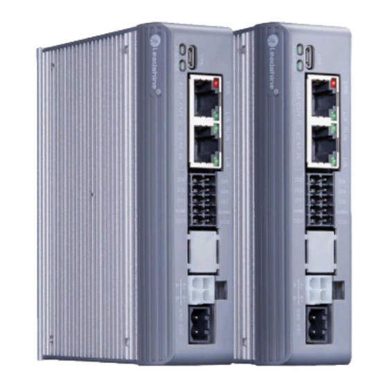
EM3E Series EtherCAT Stepper Drive User Manual 3.3 Connectors Specifications 3.3.1 Connectors Definition Figure 3.2: EM3E series connectors Name Description Input power connector Motor connector I/O signals connector EtherCAT communication connector Micro-USB tuning connector The LED for the drive's running status DIP Switches 8-bits switches: SW1 - SW7 to set 0-127 Node ID, SW8 for self test... -
Page 15: Cn1-Input Power Connector
(default) Configurable Single-ended Digital Outputs 2, OC output, Max. 30V/100mA. Brake output (default) Remark: (1) I/O interface and corresponding parameter setting refer to chapter 4.3 (2) In Leadshine MotionStudio, digital input(DI) and digital output(DO) are displayed as SI and SO. -
Page 16: Cn4-Ethercat Communication Connector
EM3E Series EtherCAT Stepper Drive User Manual 3.3.5 CN4-EtherCAT Communication Connector Name Signal Description 1, 9 E_TX+ EtherCAT TxD+ 2, 10 E_TX- EtherCAT TxD- 3, 11 E_RX+ EtherCAT RxD+ 4, 12 5, 13 6, 14 E_RX- EtherCAT RxD- 7, 15 8, 16 Cover Shield earthing... -
Page 17: Dip Switches- Sw1-Sw8
EM3E Series EtherCAT Stepper Drive User Manual 3.3.7 DIP Switches- SW1-SW8 There are 8-bit DIP switches in EM3E series drives, SW1-SW7 are used to set slave ID, SW8 is used for self-test. (1) SW1-SW7 for Slave ID The slave ID (also called Site Alias) of EM3E series can be set by the following 3 methods: 2151h 2150h DIP Switches... -
Page 18: Digital Output Wiring
EM3E Series EtherCAT Stepper Drive User Manual Note: (1) Controller/PLC/Control card should provide input DC power 12-24V, current ≥ 100mA. (2) If the polarity of input DC power is reversed, the EtherCAT stepper drive won’t work; you need to turn the wiring. -
Page 19: Ethercat Object Dictionary
4.1 Communication Object The EM3E Series drives follows the EtherCAT standard protocol, can communicate with the master stations which also supports the EtherCAT standard protocol. The parameters can be configured by master station’s PC software or Leadshine Motion Studio. Sub- Default... - Page 20 EM3E Series EtherCAT Stepper Drive User Manual RXPDO-Map 0-0xFFFFFFF Default number of 1 RXPDO-Map 01-08 UDINT object object Number Default number of 2 mapping UINT 0-32767 sub-index object 1601 RXPDO-Map 0-0xFFFFFFF Default number 01-08 UDINT object RXPDO-Map object Number Default number of 3 mapping UINT 0-32767...
-
Page 21: Manufacture Specific Object
EM3E Series EtherCAT Stepper Drive User Manual 4.2 Manufacture Specific Object Sub- Default Index Name Access Type Range Unit Remark index value 2000 Peak current R/W/S DINT 100-7000 1000 Drive's max output current. Required number of pulse to rotate 2001 Microstep resolution R/W/S DINT... - Page 22 EM3E Series EtherCAT Stepper Drive User Manual 0: Stop normally 22A9 Limit Mode DINT 0-10 1: Invalid 2: Alarm, error code 260 0: Alarm, error code 570, Quick stop selection 22B4 DINT 0~32767 1: Refer to 0x605A How long after the current switch Holding time 22BA UINT...
- Page 23 EM3E Series EtherCAT Stepper Drive User Manual Bit0 =1: RPDO mapping can’t be written by SDO; Bit0 =0: RPDO mapping can be written by SDO; Bit1=1: Detect the number of PDO Sync0 Synchronization UINT 0~32767 mapping; interface parameters Bit1=1: Don’t detect the number of PDO mapping;...
-
Page 24: I/O Configuration Object
(Decimal) = Output port function setting value + Output port polarity setting value. It is recommended to use Leadshine free tuning software MotionStudio for parameter settings, which will be very simple. In Leadshine MotionStudio, digital input(DI) and digital output(DO) are displayed as SI and SO. -
Page 25: Input Ports Filter Time & Polarity Value
EM3E Series EtherCAT Stepper Drive User Manual (2) 0x2155.01 indicates that the index is 0x2155, and bit is bit1. (3) Read State1 hen IN1~IN6 inputs are valid, at this time, it has nothing to do with whether the function is configured, bit0~bit5 of 0x2155 will change to value 1. -
Page 26: Output Ports Function & Polarity Value
EM3E Series EtherCAT Stepper Drive User Manual For Example: 1. IN1 needs to be set as quick stop function, filtering time is 20ms and polarity is NC: 0x2152+01 = 20+128+2304=2452(0x994) 2. Need to set the polarity of IN3, IN4, IN5 to NC: 0x2152+03 =128+22 =150(0x96) 0x2152+04 =128+1 =129(0x81) 0x2152+05 =128+2 =130(0x82) - Page 27 EM3E Series EtherCAT Stepper Drive User Manual 6041 Status word UINT 0-65535 Refer to chapter 6.1 0: After stopping immediately, switch on disable state; 1: After decelerating to stops at a speed value of 0x6084, switch on disable state; 2: After decelerating to stops at a speed value of 0x6085, switch on disable state;...
- Page 28 EM3E Series EtherCAT Stepper Drive User Manual ~2147483647 -2147483648 6080 R/W/S 3000 velocity limit ~2147483647 -2147483648 profile 6081 R/W/S DINT 50000 Max. Allowable velocity under PP mode velocity ~2147483647 -2147483648 6082 Start velocity R/W/S DINT Start velocity under PP mode ~2147483647 -2147483648 Profile...
-
Page 29: Xml File Or Esi File
EtherCAT Slave Information file (XML File or ESI file) is needed to connect controller with EtherCAT Master. This file is provided by Leadshine, described slave device information as XML format based on EtherCAT specifications. Please follow the EtherCAT Master software manual for importing method. -
Page 30: Error Code & Trouble Shooting
EM3E Series EtherCAT Stepper Drive User Manual 5 Error Code & Trouble Shooting When an alarm is occurred, the drive turns on the protection function and the motor stops running. EM3E has three object dictionaries that can read alarm code, and two red LED lights flash to display some of the alarm information. -
Page 31: Alarm Led
EM3E Series EtherCAT Stepper Drive User Manual 0x81e 0x821E Invalid input configuration 0x821 0xA003 Waiting for the initial state of ESM 0x822 0xA004 Waiting for ESM pre-operation state 0x823 0xA005 Waiting for ESM safe operation status 0x824 0x8224 Invalid process data input mapping 0x825 0x8225 Invalid process data output mapping... -
Page 32: Alarm Clearing
EM3E Series EtherCAT Stepper Drive User Manual Quick stop error 0x5441 Refer to 0x22B4+00 Limit switches 0x7329 Refer to 0x22A9+00 error Always 1. Restart power supply, Hardware error 2. If it still exists, the hardware failure. When the EM3E has a network communication failure, the Alarm LED2 flicker status and the error code in object 0x603F are listed in the following table. -
Page 33: Common Functions
EM3E Series EtherCAT Stepper Drive User Manual 6 Common Functions 6.1 Saving Parameters and Resetting Drive To save all storable parameters into EEPROM through Object 0x1010, need to write “0x65766173” into sub-index 01h. To reset the drive to default parameters through Object 0x1011, need to write “0x64616F6C” into sub-index 01h. - Page 34 EM3E Series EtherCAT Stepper Drive User Manual 6041+00 Status Word — Must 6064+00 Actual Position Must 606C+00 Actual Velocity P /S 607A+00 Target Position Recommend PP Mode (1) Profile 6081+00 Velocity PV Mode (3) 60FF+00 Target Velocity Recommend 6040+00 Control Word —...
- Page 35 EM3E Series EtherCAT Stepper Drive User Manual in each control mode is shown in Table 6.5. Table 6.3A: Control Word (6040h) Bit Definition 15-9 Mode General Pause Depending on the operation mode mode Invalid Invalid Invalid Invalid Immediate PP mode (1) Deceleration stop Absolute / Relative New position point...
- Page 36 EM3E Series EtherCAT Stepper Drive User Manual response effective PV mode Parameter Velocity Invalid Invalid Speed is 0 Quick stop has 0 arrival Trigger Parameter Origin Origin Position Emergency HM mode (6) response has 0 error completion arrival stop Additional information on other bits: ...
-
Page 37: Touch Probe
EM3E Series EtherCAT Stepper Drive User Manual 6.3 Touch Probe Touch probe function is to capture and record the actual position of the motor by using the input signal with the touch probe function. The EM3E driver has two input I/O signals to support the probe function and can be enabled at the same time. - Page 38 EM3E Series EtherCAT Stepper Drive User Manual Figure 6.1: Touch Probe Mode...
-
Page 39: Appendix A: Homing Methods
EM3E Series EtherCAT Stepper Drive User Manual Appendix A: Homing Methods The EM3E series drives support homing method 17-30, and method 35 & 37. Specific definition and the process of homing methods described below. Specific definition and the process of homing methods described below. Zero Position: a fixed position on the machine can correspond to a definite digital input signal, or to a Z signal Zero Point of Machine: mechanical absolute zero position Home offset: difference between zero position and zero point of machine, the value of Object 607Ch (default =... - Page 40 EM3E Series EtherCAT Stepper Drive User Manual Method 19, 20, 21, 22 require home switch. Method19 & 20 Description: The load is located on the left or right side of the home switch. Method 19 & 20 Method21 & 22 Description: The load is located on the home switch. Method 21 &...
- Page 41 EM3E Series EtherCAT Stepper Drive User Manual Method 23, 24, 25, 26 require home switch and positive limit switch. Method 23 & 24 & 25 & 26 Method 27, 28, 29, 30 require origin switch (or home switch) and negative limit switch. ...
- Page 42 EM3E Series EtherCAT Stepper Drive User Manual Method 35 & 37 use the current position as the Home switch Zero Position, it’s recommended method 37 Method 35 & 37...
-
Page 43: Appendix B: Object Dictionaries
0-0xFFFFFFFF factory setting Reset user UDIN parameters 0-0xFFFFFFFF factory setting Number UINT 0-32767 sub-index Vendor ID UINT 0-32767 4321 Leadshine code X=1---->EM3E-556E 1018 Product code UINT 0-32767 8X00 X=2---->EM3E-870E X=3---->EM3E-522E Revision number UINT 0-32767 Series number UINT 0-32767 Number Default number of 1... - Page 44 EM3E Series EtherCAT Stepper Drive User Manual RXPDO-Map UDIN Default number 01-08 0-0xFFFFFFFF object RXPDO-Map object Number Default number of 3 mapping UINT 0-32767 sub-index object 1602 RXPDO-Map UDIN Default number 01-08 0-0xFFFFFFFF object RXPDO-Map object Number Default number of 4 mapping UINT 0-32767...
- Page 45 EM3E Series EtherCAT Stepper Drive User Manual Appropriately reduce this value if Locking duration 201B R/W/S UINT 0-1500 you want to shorten the time of time locking shaft. Max time to close 201C R/W/S UINT 100-10000 1000 Usually keep the default value brake 201D Zero speed point...
- Page 46 EM3E Series EtherCAT Stepper Drive User Manual Holding current The percentage of current to peak 22BB UINT 0~100 percentage current during standby time JOG acceleration UINT 0~32767 JOG speed UINT 0~32767 JOG distance UINT 0~32767 22C2 JOG cycles UINT 0~32767 JOG direction UINT 0~32767...
- Page 47 EM3E Series EtherCAT Stepper Drive User Manual compensation 5005 UINT 0~32767 base value Synchronization 5006 UINT 0~32767 error detection Effective input and 5010 output watchdog UINT 0~32767 time Internal actual UDIN 5011 0~32767 location Homing arrival DINT 0~32767 position Homing trigger DINT 0~32767...
- Page 48 EM3E Series EtherCAT Stepper Drive User Manual 6040 Control word UINT 0-65535 Refer to chapter 6.1 6041 Status word UINT 0-65535 Refer to chapter 6.1 0: After stopping immediately, switch on disable state; 1: After decelerating to stops at a speed value of 0x6084, switch on disable state;...
- Page 49 EM3E Series EtherCAT Stepper Drive User Manual the motor reaches the Home switch and stops immediately, then reverses at low speed until it leaves the Home switch, at last stops at a distance of 10000P. New target positions are checked Software negative -2147483648...
- Page 50 EM3E Series EtherCAT Stepper Drive User Manual ~2147483647 -2147483648 Touch probe Data value sensed by touch probe 60BD DINT negative value 2 at falling edge ~2147483647 Interpolation time USIN 0-255 period value 60C21 Only for internal tuning. Interpolation time SINT -128-127 unit Touch...
-
Page 51: Appendix C: Connectors
EM3E Series EtherCAT Stepper Drive User Manual Appendix C: Connectors Package Description Brand&Specification Model Number Inside MOLEX 39012040 4PIN, 13A Motor Connector MOLEX 39000038 ANYTEK NL10100200G0G I/O Connector 2*5PIN, 3.5mm DEGSON Power 2EDGK-5.0-02P-13-1000AH Connector 2PIN, 5.0mm... -
Page 52: Appendix D: Faqs
EM3E Series EtherCAT Stepper Drive User Manual Appendix D: FAQs Communicate errors. If it is the first time to use this EtherCAT drive, check whether the version of XML file is correct. Most ► masters support scanning slave, it is recommended to create configuration in scanning way. Some masters require the connection of the network cable according to the ECAT IN and ECAT OUT. - Page 53 EM3E Series EtherCAT Stepper Drive User Manual Homing Error Wrong homing method. There are three modes of homing, when using the master homing mode, the ► operation mode object 0x6060 = 8; when using the slave homing mode, the 0x6060 = 6; when using the master-slave combination homing method, the 0x6060 value is first 8 and then 6.
Need help?
Do you have a question about the EtherCAT EM3E Series and is the answer not in the manual?
Questions and answers