Table of Contents
Advertisement
Quick Links
EM882S Digital Stepper Drive User Manual
User Manual
EM882S
Digital Microstepping Drive
Revision 1.0
©2017 Leadshine Technology Co., Ltd.
UK Official Distributor Address:
Motion Control Products Ltd, 11-15 Francis Avenue, Bournemouth, Dorset, BH11 8NX, United Kingdom
Tel: +44(0)1202 599922
Fax: +44 (0)1202 599955
Web:
www.motioncontrolproducts.com
Sales:
enquiries@motioncontrolproducts.com
Advertisement
Table of Contents

Subscribe to Our Youtube Channel
Related Manuals for Leadshine EM882S


Summary of Contents for Leadshine EM882S
- Page 1 EM882S Digital Stepper Drive User Manual User Manual EM882S Digital Microstepping Drive Revision 1.0 ©2017 Leadshine Technology Co., Ltd. UK Official Distributor Address: Motion Control Products Ltd, 11-15 Francis Avenue, Bournemouth, Dorset, BH11 8NX, United Kingdom Tel: +44(0)1202 599922 Fax: +44 (0)1202 599955 Web: www.motioncontrolproducts.com...
- Page 2 Strictly adhere to the technical information regarding installation requirements. This manual is not for use or disclosure outside of Leadshine except under permission. All rights are reserved. No part of this manual shall be reproduced, stored in retrieval form, or transmitted by any means, electronic, mechanical, photocopying, recording, or otherwise without approval from Leadshine.
-
Page 3: Table Of Contents
EM882S Digital Stepper Drive User Manual Table of Contents Introduction................................1 1.1 Features ................................1 1.2 Applications ................................. 1 Specifications ................................2 2.1 Electrical Specifications............................2 2.2 Environment ................................ 2 2.3 Mechanical Specifications ............................ 2 2.4 Elimination of Heat .............................. 3 3. -
Page 4: Introduction
(10-25%), quicker response time, control command smoothing, motor selector, etc. The EM882S is able to power 2 phase (1.8°) and 4 phase (0.9°) stepper motors smoothly with very low motor heating & noise. It can take 20-80VDC supply voltage and output 0.5 to 8.2A current. All the micro step, output current configurations and motor model selection can be easily done via built in DIP switches. -
Page 5: Specifications
EM882S Digital Stepper Drive User Manual 2. Specifications 2.1 Electrical Specifications Parameters Typical Unit Output Current 8.2 (5.9 RMS) Supply Voltage 24 - 72 Logic signal current Pulse input frequency Minimal pulse width μs Minimal direction setup μs Isolation resistance MΩ... -
Page 6: Elimination Of Heat
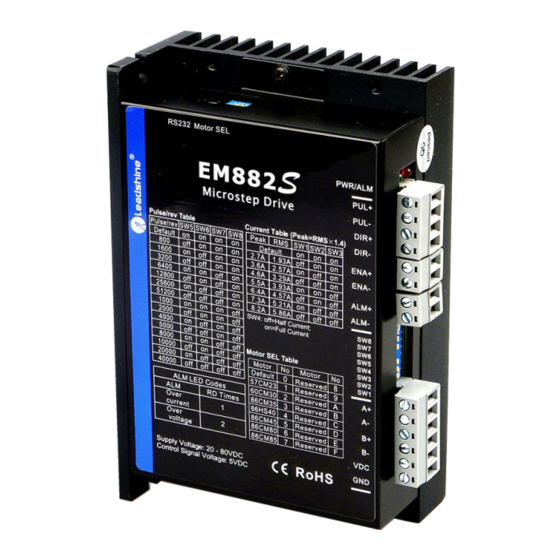
Connectors, DIP switches, and LED locations The EM882S has 4 connectors P1, P2, P3 and P4, 2 DIP switch S1 and rotation switch S2. P1 is for control signal connections, P2 is for fault output, P3 is for motor and power connection, P4 is for fine tuning. -
Page 7: P2 - Fault Output Connector
3.5 Status LED Lights There are two LED lights for EM882S. The GREEN one is the power indicator which should be always on in normal circumstance. The RED one is a drive status indication light, which will be OFF while working normally but ON and flash 1 or 2 times in a 3-second period in the case of enabled over-current or over-voltage protection. -
Page 8: Fault Output Connection
Figure 6 Sourcing output 5. Stepper Motor Connections EM882S can drive 2-phase and 4-phase bipolar hybrid stepper motors with 4, 6, or 8 leads, Motion Control Products also offers easy-to-use and good-performance motors with 4-leads, ideal for running with the EM882S: https://www.motioncontrolproducts.com/electric-motors/stepper-motors/hybrid-stepper-motors/... -
Page 9: 6-Lead Motor Connection
Although setting the drive output current to 1.4 times of driven motor phase current will get the most torque, it is suggested to set an EM882S’s output current (peak of sinusoidal) to no more than 1.2 times the stepper motor’s phase current to prevent overheating. Refer to the figure 11 for how to connect an 8-lead stepper motor for parallel connection. -
Page 10: Regulated Or Unregulated Power Supply
ON duration of the PWM cycle, but not during the OFF duration. 6.2 Power Supply Sharing Multiple EM882S drives can share the same power supply, if that power supply has enough capacity. To avoid cross interference, connect each EM882S DIRECTLY to that shared power supply separately instead of connecting those power connectors of drives in daisy-chain connection. -
Page 11: Idle Current Configuration (Sw4)
EM882S will be automatically reduced to the configured percentage. 7.3 Micro Step Configuration (SW5-8) Each EM882S has 8 micro step settings which can be configured through DIP switch SW5, SW6, SW7 and SW8. See the following table for detail. When they are set to ON, ON, ON,ON, the microstep can be set via Leadshine ProTuner. -
Page 12: Auto-Tuning And Motor Model Selection (Rotary Switch)
It is better to separate them by at least 10 cm; otherwise the disturbing signals generated by motor will easily disturb pulse direction signals, causing motor position error, system instability and other failures. ⚫ If only one power supply serves multiple EM882S drives, separately connecting the drives to the power supply is recommended instead of daisy-chaining. ⚫... -
Page 13: Typical Connection
EM882S Digital Stepper Drive User Manual flowing through motor coils (even when motor is at standstill). Pulling or plugging connector P4 with power on will cause extremely high back-EMF voltage surge, which may damage the drive. 9. Typical Connection A complete stepping system should include stepping motor, stepping drive, power supply and controller (pulse generator). -
Page 14: Protection Functions
11. Protection Functions EM882S incorporates are built with over-voltage and over-current error protections. When it is under error protection, the red LED light will blink for 1 or 2 or 4 times in a period of 3 seconds. If fault output connection is connected, the impedance mode between ALM+ and ALM- will be changed (See “Fault Output Configuration”... -
Page 15: Troubleshooting
EM882S Digital Stepper Drive User Manual 12. Troubleshooting In the event that your drive doesn’t operate properly, the first step is to identify whether the problem is electrical or mechanical in nature. The next step is to isolate the system component that is causing the problem. As part of this process you may have to disconnect the individual components that make up your system and verify that they operate independently. -
Page 16: Warranty
EM882S Digital Stepper Drive User Manual 13. Warranty TWELVE MONTH LIMITED WARRANTY Motion Control Products Ltd warrants its products against defects in materials and workmanship for a period of 12 months from the shipping/purchasing date. During the warranty period Motion Control Products, at their discretion, will repair or replace products that are proved to be defective.
Need help?
Do you have a question about the EM882S and is the answer not in the manual?
Questions and answers