Table of Contents
Advertisement
Quick Links
ES2-3DA2306 Vector Easy Servo Drive User Manual
User Manual
ES2-3DA2306
Vector Easy Servo Drive
Revision 1.0
Revision 1.0
©2016 Leadshine Technology Co., Ltd.
Address: Floor 11, Block A3, Nanshan iPark, Xueyuan Avenue 1001, Shenzhen, Guangdong, 518055, China
Tel: (86)755-26409254
Fax: (86)755-26402718
Web:
Sales:
www.leadshine.com
sales@leadshine.com
Support:
tech@leadshine.com
Advertisement
Table of Contents

Subscribe to Our Youtube Channel
Related Manuals for Leadshine ES2-3DA2306


Summary of Contents for Leadshine ES2-3DA2306
- Page 1 ES2-3DA2306 Vector Easy Servo Drive User Manual User Manual ES2-3DA2306 Vector Easy Servo Drive Revision 1.0 Revision 1.0 ©2016 Leadshine Technology Co., Ltd. Address: Floor 11, Block A3, Nanshan iPark, Xueyuan Avenue 1001, Shenzhen, Guangdong, 518055, China Tel: (86)755-26409254 Fax: (86)755-26402718...
- Page 2 Strictly adhere to the technical information regarding installation requirements. This manual is not for use or disclosure outside of Leadshine except under permission. All rights are reserved. No part of this manual shall be reproduced, stored in retrieval form, or transmitted by any means, electronic, mechanical, photocopying, recording, or otherwise without approval from Leadshine.
-
Page 3: Table Of Contents
4.1Wiring Diagrams..............................12 4.1.1 Power Wiring............................12 4.1.2 Control Signal Wiring..........................12 4.2 Sequence Chart of Control Signals........................15 4.3 Configuring ES2-3DA2306..........................15 4.3.1 Configuring ES2-3DA2306 by the on-board HMI................. 15 4.3.2 Configuring ES2-3DA2306 by the ProTuner..................17 5 Frequently Asked Questions............................23 6 Warranty..................................24... -
Page 4: Introductions
Over voltage, over-current, and position-error protection 1.2 Applications Due to combining the features of both AC servo drives and stepper drives, Leadshine ES2 series easy servo drives are suitable for both upgrading conventional stepper systems, and replacing AC servo systems which have closed loop and high torque requirements. -
Page 5: I/O Interface Specifications
ES2-3DA2306 Vector Easy Servo Drive User Manual 2.2 I/O Interface Specifications Parameters ES2-3DA2306 Command Input Step/Direction, CW/CCW Enable/Disable Input Differential Alarm Signal Output Isolated OC Output Encoder Signal Output ABZ Output Tuning Interface On-board HMI or RS232 communication Regeneration Resistor Built-in ( 50 Ohm, 100W), Support External 2.3 Mechanical Specifications... -
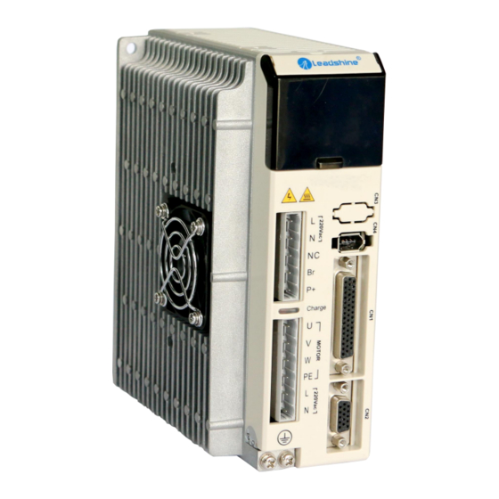
Page 6: Connectors And Pin Assignments
ES2-3DA2306 Vector Easy Servo Drive User Manual 3 Connectors and Pin Assignments Heat Sink On-board HMI Self-test, On-board Configuration Main Power Input Braking Resistor RS232 Configuration Port Connection Motor Outputs Control Signal Connector Pulse, Direction, Enable Inputs and Fault Output... - Page 7 ES2-3DA2306 Vector Easy Servo Drive User Manual bandwidth) Direction Signal: In single-pulse mode, this signal has low/high voltage levels, DIR+ representing two directions of motor rotation. In double-pulse mode (software configurable), this signal is counter-clock (CCW) pulse, active both at high level and low level.
-
Page 8: Rs232 Communication Connector For Tuning Cn3
ES2-3DA2306 Vector Easy Servo Drive User Manual EGND +5V output return ground No Connection. No Connection. Ground terminal for shield Encoder Z+ input Encoder Z- input No Connection. No Connection. Encoder A- input Encoder B- input External +5V power input need if the required current >50mA, no connection as normally No Connection. -
Page 9: Connector Pin-Out
ES2-3DA2306 Vector Easy Servo Drive User Manual Internal DC bus voltage output. The regeneration resistor should be connected between BR1 and P+. Motor & Control Power Supply Connector Name Description Motor phase U Motor phase V Motor phase W Case ground Control Power Supply from 150VAC to 240VAC. -
Page 10: Matching Esm Series Easy Servo Motors
ES2-3DA2306 Vector Easy Servo Drive User Manual CN3 – RS232 & RS485 Connector 1 GND 3 +5V 5 NC 4 RxD 2 TxD 6 NC CN5 – Main Power Supply Connector CN6 – Motor & Control Power Supply Connector 3.7 Matching ESM Series Easy Servo Motors... -
Page 11: Getting Start
ES2-3DA2306 Vector Easy Servo Drive User Manual 3.9 Motor Encoder Extension Cable CABLEG-BMXMX Pin Assignments A: HDD15 Female B: HDD15 Male Wire Color Name Description Black Channel A+ +5V power input White +5V GND Orange Channel Z+ Grey Channel Z-... -
Page 12: Wiring Diagrams
Power Extension Cable 4.1.1 Power Wiring The ES2-3DA2306 requires two powers input as follows. The main power is used to energize the motor and the control power is used for logic circuit. Typically they can share the same AC power. - Page 13 ES2-3DA2306 Vector Easy Servo Drive User Manual Multiple Drives It is recommended to have multiple drives to share one power supply to reduce cost, if the supply has enough capacity. To avoid cross interference, DO NOT daisy-chain the power supply input pins of the drives. Instead, please connect them to power supply separately.
- Page 14 ES2-3DA2306 Vector Easy Servo Drive User Manual Connection to controller of sinking output Connection to controller of sourcing output...
-
Page 15: Sequence Chart Of Control Signals
ES2-3DA2306 Vector Easy Servo Drive User Manual Wiring Notes In order to improve anti-interference performance of the drive, it is recommended to use twisted pair shield cable. To prevent noise incurred in PUL/DIR signal, pulse/direction signal wires and motor wires should not be tied up ... - Page 16 ES2-3DA2306 Vector Easy Servo Drive User Manual 7-segment Display Left Shift Digits Decrease or Next Enter, Confirm Mode Switching Increase or previous There are 4 operation modes in the on-board HMI. Users can switch between these modes by pressing the “Mode”...
-
Page 17: Configuring Es2-3Da2306 By The Protuner
“d07 Pn” Bus voltage which is 1/10 of the actual value. “d08 no” Drive version number. 4.3.2 Configuring ES2-3DA2306 by the ProTuner Leadshine also provide the tuning software named ProTuner to configure the parameter of ES2-3DA2306. Parameter list Default Definition Property... - Page 18 ES2-3DA2306 Vector Easy Servo Drive User Manual Pulse /Rev R/W/S 1600 200—20000 Motor runs a round needs pulse Four multiplying frequency for Encoder resolution R/W/S 4000 200—51200 1000 line encoder Position following R/W/S 1000 1—6000 Unit:pulse error The percent of Maximum current.
- Page 19 ES2-3DA2306 Vector Easy Servo Drive User Manual Resonance 0—1000 Invalid compensation 0:Unlock Choosing Shaft R/W/S 0—1 Locking in Disable 1:Lock Reset fault by enable 0-Disable 0—1 input R/W/S 1-Enable Choosing Winding 0-No winding short 30008 Short R/W/S 0—1 1-Winding short Lower Bridge Arm 0:Pend output...
- Page 20 ES2-3DA2306 Vector Easy Servo Drive User Manual Tuning proportionality 30064 R/W/S 0—200 Speed loop gain in running 0-Disable, 1-Enable(for special Self-test Enable R/W/S 0—1 application) 1:Enable 0:Disable bit0:Over current Fault Detection bit1:Over voltage Enable R/W/S 4739 0—65535 Bit7:Position following error (bit operation) Bit9:Brake output...
- Page 21 Encoder resolution 200—20000 4000 The encoder of easy servo motor from Leadshine is 1000, 2500, 5000PPR, so If you use these motors, the value must be 4000, 10000, 20000 respectively. 5000 PPR encoder is recommended for the better performance and easier tuning.
- Page 22 ES2-3DA2306 Vector Easy Servo Drive User Manual The tolerance for position following error, if the error is over this value of setting, drive will display ERR20 . NO. in Protuner NO. on HMI panel Range unit default Lock Shaft Current...
-
Page 23: Frequently Asked Questions
ES2-3DA2306 Vector Easy Servo Drive User Manual NO. in Protuner NO. on HMI panel Range unit default Speed Loop Sampling Frequency 0--31 Smoothing the speed loop overshoot, higher value will reduce the vibration when the speed loop Kp is large enough. -
Page 24: Warranty
Leadshine Technology Co., Ltd. warrants its products against defects in materials and workmanship for a period of 12 months from shipment out of factory. During the warranty period, Leadshine will either, at its option, repair or replace products which proved to be defective. - Page 25 ES2-3DA2306 Vector Easy Servo Drive User Manual...
Need help?
Do you have a question about the ES2-3DA2306 and is the answer not in the manual?
Questions and answers