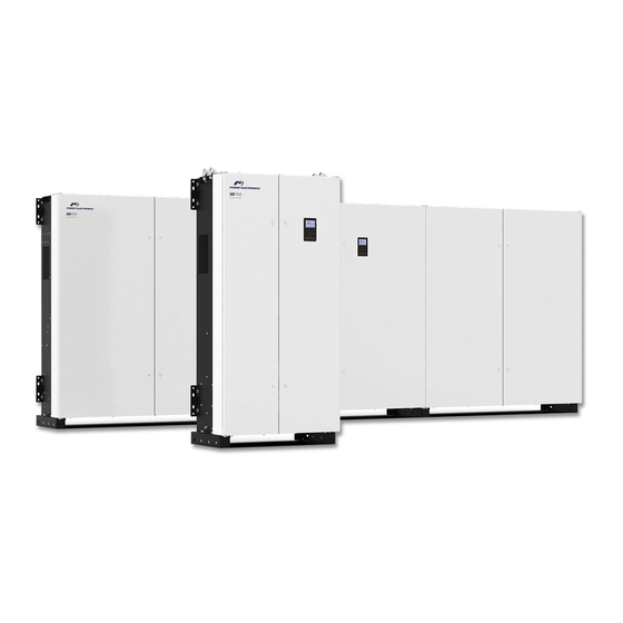
Power Electronics SD750 Manual
Software and programming
Hide thumbs
Also See for SD750:
- Hardware and installation manual (112 pages) ,
- Accessories manual (42 pages) ,
- Manual (32 pages)
Table of Contents
Advertisement
Quick Links
Advertisement
Table of Contents

Summary of Contents for Power Electronics SD750
- Page 1 SD750 SOFTWARE AND PROGRAMMING MANUAL LOW VOLTAGE VARIABLE SPEED DRIVE...
- Page 3 Software and Programming Manual Edition: May 2021 SD75SW01LI Rev. L...
-
Page 4: About This Manual
This manual contains important instructions for the installation and maintenance of Power Electronics SD750 variable speed drives. TARGET AUDIENCE This manual is intended for qualified customers who will install, operate and maintain Power Electronics SD750 variable speed drives. Only trained electricians may install and commission the drives. - Page 5 Description of programming parameters. Modbus Communication. The equipment and technical documentation are periodically updated. Power Electronics reserves the right to modify all or part of the contents of this manual without previous notice. To consult the most updated information of this product, you may access our website www.power-electronics.com, where the latest version of this manual can be downloaded.
-
Page 6: Table Of Contents
SD750 POWER ELECTRONICS TABLE OF CONTENTS ABOUT THIS MANUAL ..........................2 ACRONYMS ..............................7 SAFETY SYMBOLS ............................. 9 SAFETY INSTRUCTIONS .......................... 10 1. DISPLAY UNIT AND CONTROL KEYPAD ..................11 Keypad Unit Description ........................11 LED for status indication ........................12 Alphanumeric LCD Display ...................... - Page 7 POWER ELECTRONICS SD750 Subgroup 4.3: Analogue Input 2 / Pulse ..................45 Subgroup 4.4: Analogue Input 3 / PT100 ..................47 Subgroup 4.5: Analogue input 4 ...................... 48 Subgroup 4.6: Analogue input 5 ...................... 48 Subgroup 4.7: Analogue input 6 ...................... 48 Subgroup 4.8: Analogue input 7 ......................
- Page 8 SD750 POWER ELECTRONICS Subgroup 21.1: Ethernet ........................77 Subgroup 21.2: Client TCP ......................77 Subgroup 21.3: EtherNet / IP ......................77 Subgroup 21.4: Profinet ........................77 Group 23: Expansion .......................... 78 Subgroup 23.1: PT100 ........................78 Subgroup 23.2: Input/Output ......................78 Subgroup 23.3: Communications.....................
-
Page 9: Acronyms
POWER ELECTRONICS SD750 ACRONYMS The terms commonly used in the documentation of Power Electronics’ products are listed in the table below. Please notice this is a general series of terms and it encompasses all our product divisions (industrial, solar, storage, and electric mobility), thus, some of the following expressions may not apply to this particular manual. - Page 10 SD750 POWER ELECTRONICS ACRONYM MEANING Residual Current Device Residual Current Monitor RFID Radio Frequency Identification State Of Charge – referred to battery State Of Health – referred to battery. It compares the actual state of the battery to its initial conditions.
-
Page 11: Safety Symbols
POWER ELECTRONICS SD750 SAFETY SYMBOLS Always follow safety instructions to prevent accidents and potential hazards from occurring. In this manual, safety messages are classified as follows: Identifies potentially hazardous situations where dangerous voltage may be present, which if not avoided, could result in minor personal injury, serious injury or death. -
Page 12: Safety Instructions
In order to appropriately use the drive, please, follow all instructions described in the Hardware and Installation Manual which refer to transportation, installation, electrical connection and commissioning of the equipment. Power Electronics accepts no responsibility or liability for partial or total damages resulting from incorrect use of equipment. CAUTION Read carefully the Hardware and Installation Manual and all documentation related to the drive to ensure its safe use and prevent personal injuries and equipment damage. -
Page 13: Display Unit And Control Keypad
The graphic display is a removable display unit for remote installation. There is a LED indicator integrated in the Power Electronics logo on the display which provides information about the operation status of the equipment. In addition, there is a 2.8 '' LCD screen and eight control keys. -
Page 14: Led For Status Indication
SD750 POWER ELECTRONICS LED for status indication The status LED shows the drive status while it is on. It is located in the Power Electronics logo, and will change its color as follows: • Green: The equipment is in run status. -
Page 15: Menu
POWER ELECTRONICS SD750 Enter or exit the menu. It can also be used as editing help during parameter adjustment, allowing to use the multiplier to set the desired value of a variable (manual precision) or to modify the rate of updating the value according to the time pressed (automatic precision). - Page 16 SD750 POWER ELECTRONICS ▪ Versions: This menu contains the information of the versions associated with the equipment in terms of MCF, uP, DSP, HW, expansion board and display. ▪ Custom view creator: This menu allows creating custom display screens on the main screen, selecting the parameters to be included for any of the three lines of the new screen to be customized.
-
Page 17: Status & Warning Messages
(F42, F43, F59, F89, F104, F105, F106…). After the fault the drive will stop with ramp. ‘Flying start’ operation must be configured if required. The SD750 will search Flying start for the actual motor shaft speed once the drive has received a start command. -
Page 18: List Of Warning Messages
SD750 is working according to inch speed 1 command and ‘Start + Inch speed 1' mode is active. When operated in this mode the ‘Start + Inch speed 1’... - Page 19 POWER ELECTRONICS SD750 Warning Acronym Name Description The drive does not increase speed because input voltage is not Cells enough. This warning only applies to permanent magnet synchronous motors. Motor speed has reached the minimum speed limit that is active at...
-
Page 20: Fault Messages. Descriptions And Actions
FAULT MESSAGES. DESCRIPTIONS AND ACTIONS When a fault occurs, the SD750 will stop the motor, showing the fault in the display. Without resetting the fault it is possible to navigate through the display lines where we will have access to the rest of the display parameters.


Need help?
Do you have a question about the SD750 and is the answer not in the manual?
Questions and answers