Power Electronics SD 500 Series Manual
Ethernet communications. communication network.
Hide thumbs
Also See for SD 500 Series:
- Programming and software manual (99 pages) ,
- Hardware and installation manual (76 pages) ,
- Manual (73 pages)
Table of Contents
Advertisement
Quick Links
Advertisement
Table of Contents

Related Manuals for Power Electronics SD 500 Series


Summary of Contents for Power Electronics SD 500 Series
- Page 1 Ethernet Communication Communication Network...
- Page 3 Communication Network Ethernet Communication Edition: November 2016 SD50BC03BI Rev. B...
- Page 4 SD500 – ETHERNET POWER ELECTRONICS...
- Page 5 SD500 – ETHERNET POWER ELECTRONICS SAFETY SYMBOLS Always follow safety instructions to prevent accidents and potential hazards from occurring. In this manual, safety messages are classified as follows: Identifies potentially hazardous situations where dangerous voltage may be present which if not...
- Page 6 17 / 11 / 2016 Misprints and contents update. The equipment and technical documentation are periodically updated. Power Electronics reserves the right to modify all or part of the contents of this manual without previous notice. To consult the most updated information of this product, you may access through our website www.power-electronics.us...
-
Page 7: Table Of Contents
SD500 – ETHERNET POWER ELECTRONICS TABLE OF CONTENTS SAFETY INSTRUCTIONS ................7 PART I: ETHERNET BOARD ................ 13 INTRODUCTION ..................15 1.1. Ethernet Networks ................15 1.1.1. Introduction ................15 1.1.2. Types of Ethernet Networks ............ 16 1.2. Description of the Ethernet Board ........... 17 TECHNICAL CHARACTERISTICS ............ - Page 8 SD500 – ETHERNET POWER ELECTRONICS PART II: Modbus TCP/IP PROTOCOL ............33 INTRODUCTION ..................35 1.1. Modbus TCP/IP Protocol ..............35 1.1.1. Modbus Protocol TCP/IP Architecture ........35 1.2. Modbus TCP/IP ................37 1.2.1. Modbus TCP/IP Protocol Description ........38 1.2.2.
-
Page 9: Safety Instructions
Power Electronics accepts no responsibility or liability for partial or total damages resulting from inappropriate equipment use. Please, pay careful attention to the following recommendations:... - Page 10 SD500 – ETHERNET POWER ELECTRONICS Wiring and periodic inspections should be performed at least 10 minutes after disconnecting the input power and after checking the DC Link voltage is discharged with a meter (below 30VDC). Otherwise, you may get an electric shock.
- Page 11 SD500 – ETHERNET POWER ELECTRONICS NOTICE RECEPTION Material of Power Electronics is carefully tested and perfectly packed before leaving the factory. In the event of transport damage, please ensure that you notify the transport agency and POWER ELECTRONICS: 902 40 20 70 (International +34 96 136 65 57) or your nearest agent, within 24hrs from receipt of the goods.
- Page 12 SD500 – ETHERNET POWER ELECTRONICS CONNECTION PRECAUTIONS To ensure correct operation of the inverter it is recommended to use a SCREENED CABLE for the control wiring. For EMERGENCY STOP, make sure supply circuitry is open. Do not disconnect motor cables if input power supply remains connected.
- Page 13 SD500 – ETHERNET POWER ELECTRONICS OPERATION PRECAUTIONS When the Auto Restart function is enabled, keep clear of driven equipment, as the motor will restart suddenly after a fault is reset. The “STOP / RESET” key on the keypad is active only if the appropriate function setting has been made.
- Page 14 SD500 – ETHERNET POWER ELECTRONICS...
-
Page 15: Part I: Ethernet Board
SD500 – ETHERNET POWER ELECTRONICS PART I ETHERNET BOARD... - Page 16 SD500 – ETHERNET POWER ELECTRONICS...
-
Page 17: Introduction
SD500 – ETHERNET POWER ELECTRONICS 1. INTRODUCTION 1.1. Ethernet Networks 1.1.1. Introduction Ethernet is used to designate a family of frame-based computer networking technologies for local area networks (LANs). It was mainly developed by Xerox Corporation, Intel Corporation and Digital Equipment Corporation (DEC) companies in 1980, and has continued evolving since then. -
Page 18: Types Of Ethernet Networks
SD500 – ETHERNET POWER ELECTRONICS 1.1.2. Types of Ethernet Networks There are different implementations for Ethernet network, according to the physical environment referred. The existing Ethernet technologies differ in the following characteristics: Transmission speed: Transmission capacity environment in Mbps. -
Page 19: Description Of The Ethernet Board
SD500 – ETHERNET POWER ELECTRONICS 1.2. Description of the Ethernet Board The Ethernet board for SD500 drives allows integrating the drive in a LAN (Local Area Network). It supports the TCP/IP standard communication protocol and the industrial application layer protocol Ethernet/IP for industrial automation applications. -
Page 20: Technical Characteristics
SD500 – ETHERNET POWER ELECTRONICS 2. TECHNICAL CHARACTERISTICS 2.1. General Information 2.1.1. Contents of the Ethernet Board Kit The kit of the Ethernet board contains: o 1 Ethernet board. o 1 Fixation screw. o 1 Technical manual. 2.1.2. Specifications of Ethernet Board o Device Type: Network adapter. -
Page 21: Local Indicators
SD500 – ETHERNET POWER ELECTRONICS 2.1.3. Local indicators The Ethernet board includes 4 leds that supply information about the communication status speed and, depending communication case (Modbus/TCP or Ethernet IP), information about the working status. To obtain more detailed information about leds, please, see section ‘3.2.3. -
Page 22: Installation And Connection
3.1. Installation of Ethernet Board The Ethernet board is directly connected to the drive of the SD500 Series from Power Electronics (through a connector) with the purpose of integrating the equipment in an Ethernet local area network (LAN) with TCP/IP or Ethernet/IP as network protocol. Therefore, one Ethernet board will be necessary per each equipment which is going to be connected to the network. -
Page 23: Connections Of The Ethernet Board
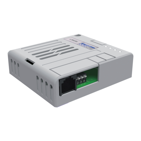
SD500 – ETHERNET POWER ELECTRONICS 3.2. Connections of the Ethernet Board There are connectors, four leds and four switches on Ethernet board. There is a connector used to connect the board to the SD500 drive and a RJ45 connector for connecting it to the Ethernet network. -
Page 24: Switches Description
SD500 – ETHERNET POWER ELECTRONICS 3.2.2. Switches description Figure PI-3.3 Location of switches on Ethernet Board There are two communication protocols for using the SD500 Ethernet optional board: Modbus TCP and Ethernet IP. Switch 1 controls the communications protocol. Switches 2, 3 and 4 are not available. -
Page 25: Leds Description
SD500 – ETHERNET POWER ELECTRONICS 3.2.3. Leds description The Ethernet board has four leds that show, at all times, its status. Led1 and Led2 behaviour depends on the active communication protocol (Modbus TCP or Ethernet IP), while the remaining two leds, number 3 and 4 have the same behaviour in both protocols Figure PI-3.4 Location of leds on Ethernet Board... - Page 26 SD500 – ETHERNET POWER ELECTRONICS Case of Ethernet IP communication OFF: client and TCP are not in connection. Flashing: client and TCP are connected and registered. Green Communication is possible. ON: connection has been made and it is communicating. LED1 NS led OFF: the network has no problem.
-
Page 27: Ethernet Board Configuration
SD500 – ETHERNET POWER ELECTRONICS 4. ETHERNET BOARD CONFIGURATION 4.1. Ethernet Parameters Setting There are several parameter groups used to configure SD300 drives operation in a communication network: [G3 References] [G4 Inputs G4.1 Digital Inputs] [G21 Net Comms G21.1 General, G21.2 Modbus TCP/IP,... -
Page 28: Subgroup 4.1 - G4.1: Digital Inputs
SD500 – ETHERNET POWER ELECTRONICS 4.1.2. Subgroup 4.1 – G4.1: Digital Inputs Drive control modes need to be defined in order to cede the control to the communication network. Name / Set on Display Range Function Description Set the control mode for sending commands to the drive (Start/Stop, Reset, ...). -
Page 29: Subgroup 21.1 - G21.1: General
SD500 – ETHERNET POWER ELECTRONICS 4.1.3. Subgroup 21.1 – G21.1: General Set on Parameter Description Range Function OPT. FUNCTION Disabled Enabled When the equipment is running, the Option 1 ComUpdate=NO G21.1.1 / To enable parameters are expressed by the values... -
Page 30: Subgroup 21.2 - S21.2: Modbus Tcp/Ip
SD500 – ETHERNET POWER ELECTRONICS Set on Parameter Description Range Function Set the Subnet Mask address of the local network of the user. This address must be 6 NET A.B= G21.1.4 / Subnet mask 0 to provided by the network administrator of Subnet Mask A.B... -
Page 31: Subgroup 21.3 - S21.3: Ethernet Ip
SD500 – ETHERNET POWER ELECTRONICS 4.1.5. Subgroup 21.3 – S21.3: Ethernet IP Screen / Default Name / Range Function during value Description 1 ComUpdate=0 G21.3.1 /Comm. Enable or disable communications update. Comm Update update 2 RdInstance=70 G21.3.2 / Ethernet Select the Ethernet communication input... - Page 32 SD500 – ETHERNET POWER ELECTRONICS Screen / Default Name / Range Function during value Description 0x0000 11 ParaRd8=0x0000 G21.3.11 / Read Read input address 8. Param Read 8 address 8 0xFFFF 12 WrInstanc=20 G21.3.12 / Ethernet Select the output instance of the Ethernet...
-
Page 33: Lost Command Mode
SD500 – ETHERNET POWER ELECTRONICS 4.2. Lost Command Mode The action that should be taken by the drive in case the communication is lost must be defined. This is done using the following parameters: Screen / Default Name / Range... - Page 34 SD500 – ETHERNET POWER ELECTRONICS...
-
Page 35: Part Ii: Modbus Tcp/Ip Protocol
SD500 – ETHERNET POWER ELECTRONICS PART II MODBUS TCP/IP PROTOCOL... - Page 36 SD500 – ETHERNET POWER ELECTRONICS...
-
Page 37: Introduction
SD500 – ETHERNET POWER ELECTRONICS 1. INTRODUCTION 1.1. Modbus TCP/IP Protocol TCP/IP (Transmission Control Protocol / Internet Protocol) is a set of protocols that define a group of rules and premises to allow the interchange of information between heterogeneous systems by means of local area nets (LAN), wide area nets (WAN), telephonic public networks, etc. - Page 38 SD500 – ETHERNET POWER ELECTRONICS TCP/IP layers or levels are following: Application Level: encompasses applications that make easy the user life, such as email, Web navigator, FTP files interchange, Modbus, etc. Transport Level: this is, in fact, the level which allows two TCP/IP connected systems to talk between them.
-
Page 39: Modbus Tcp/Ip
SD500 – ETHERNET POWER ELECTRONICS 1.2. Modbus TCP/IP Modbus TCP/IP is an extension of Modbus protocol that allows using it over the TCP/IP transport layer. Therefore, Modbus TCP can be used in Internet. There are many advantages for people who install lines and automation companies: ... -
Page 40: Modbus Tcp/Ip Protocol Description
SD500 – ETHERNET POWER ELECTRONICS 1.2.1. Modbus TCP/IP Protocol Description Modbus messenger service provides a Client/Server communication model between devices connected in an Ethernet network. This model of Client / Server is based on four types of messages: Modbus Request ... -
Page 41: Modbus Tcp/Ip Protocol Architecture
SD500 – ETHERNET POWER ELECTRONICS Modbus messenger services (Client/Server model) are used for real time data interchange: Between two device applications. Between one device application and one device. Between HMI / SCADA applications and devices. Between one PC and one device program providing "online"... -
Page 42: Modbus Tcp Parameters Setting
SD500 – ETHERNET POWER ELECTRONICS 2. MODBUS TCP PARAMETERS SETTING an extension of Modbus protocol that allows using it over the TCP/IP transport layer and, therefore, in Internet. There is a parameter group in the SD300 drive used to configure it to operate with Modbus TCP connected to an Ethernet network with TCP/IP protocol. -
Page 43: Function Code Description
SD500 – ETHERNET POWER ELECTRONICS 2.2. Function Code description Modbus TCP is divided into Client and Server. The Client sends a command and the Server replies to it. Generally, Clients can be PLC, HMI, or PC and the Server is the VFD. -
Page 44: Write Multiple Register
SD500 – ETHERNET POWER ELECTRONICS Frame structure of a response from Server to Master Section Length Value Function code 1 Byte Comm. Address 2 Bytes 0x0000 to 0xFFFF Data Value 2 Bytes 0x0000 to 0xFFFF 2.2.3. Write multiple register Frame structure of a request from Client to Server... - Page 45 SD500 – ETHERNET POWER ELECTRONICS Exception code type Exception code type Code Value Illegal function When an unsupported function is requested. Illegal data address Request or modification of data in an unused address. When trying to modify data to a value out of the permissible Illegal data value range.
-
Page 46: Modbus Address List
SD500 – ETHERNET POWER ELECTRONICS 3. MODBUS ADDRESS LIST 3.1. Common Area Address Parameter Scale Units Data value 40001 Inverter model B: SD500 0: 0.75kW 1: 1.5kW 2: 2.2kW 3: 3.7kW 4: 5.5kW 5: 7.5kW 6: 11kW 40002 Inverter capacity 7: 15kW 8: 18.5kW... - Page 47 SD500 – ETHERNET POWER ELECTRONICS Address Parameter Scale Units Data value Bit 0: Stop Bit 1: Forward run Bit 2: Reverse run Bit 3: Fault reset Bit 4: Emergency stop Bit 5: Not used Bit 6 – 7: Reference introduction...
- Page 48 SD500 – ETHERNET POWER ELECTRONICS Address Parameter Scale Units Data value 40008 Acceleration time 40009 Deceleration time 40010 Output current 40011 Output frequency 0.01 40012 Output voltage 40013 DC link voltage 40014 Output power 40015 Bit 0: Stop Bit 1: Forward run...
- Page 49 SD500 – ETHERNET POWER ELECTRONICS Address Parameter Scale Units Data value 40019 Voltage input V1 40020 Voltage input V2 (Option E/S) 40021 Current input I1 40022 Output speed 0: Hz 40027 Display unit 1: rpm 40028 Number of poles Motor poles visualization...
- Page 50 SD500 – ETHERNET POWER ELECTRONICS...
-
Page 51: Part Iii: Ethernet/Ip Protocol
SD500 – ETHERNET POWER ELECTRONICS PART III ETHERNET/IP PROTOCOL... - Page 52 SD500 – ETHERNET POWER ELECTRONICS...
-
Page 53: Introduction
SD500 – ETHERNET POWER ELECTRONICS 1. INTRODUCTION 1.1. Ethernet/IP Protocol Ethernet/IP is an application layer protocol that was designed for the industrial environment. It is the finished product from four groups that have joined forces to develop and promote for industrial automation... -
Page 54: Ethernet/Ip Technology
SD500 – ETHERNET POWER ELECTRONICS 1.1.1. Ethernet/IP Technology Introduced at the beginning of 2000, Ethernet/IP is one of the pioneers in Ethernet solutions for industrial environment. The main reason is that it is based on open technology, using the same application layer as DeviceNet and ControlNet, and it is called Common Industrial Protocol (CIP). -
Page 55: Cip Protocol
SD500 – ETHERNET POWER ELECTRONICS With I/O messages, the application data field only contains input/output data in real time. The meaning of data is linked to an identifier defined when connection is established, reducing the processing time in the node at execution time. This type of messages provides high efficiency, low load and the required performance for real-time control. - Page 56 SD500 – ETHERNET POWER ELECTRONICS The CIP model is, on the upper layers, a model only focused to objects. Each object has attributes (data), services (instructions), connections and behaviours (relations between the values of the attributes and the services). Objects implement basic functions of: ...
-
Page 57: Cip Protocol To Ethernet/Ip
SD500 – ETHERNET POWER ELECTRONICS 1.2.1. CIP Protocol for Ethernet/IP The advantages of the CIP protocol layer over Ethernet/IP are abundant. Offering consistent device access means that one configuration tool can be used to configure CIP devices on different networks from one access point without proprietary software. -
Page 58: Cip Objects
SD500 – ETHERNET POWER ELECTRONICS 2. CIP OBJECTS Next, the different objects implemented by the drive are listed. In order to obtain detailed information about these objects and attribute, refer to the CIP specifications. Name Class ID Identity Object 0x01... - Page 59 SD500 – ETHERNET POWER ELECTRONICS The upper byte stands for the major revision, and the lower byte stands for the minor revision. For example, 0x0102 means 2.01. Definition of Status bit: Meaning 0: master is not connected with any device...
-
Page 60: Motor Data Object
SD500 – ETHERNET POWER ELECTRONICS 2.2. Motor Data Object Instance number 1 is implemented for this standard object and the following attributes are supported. Attribute Description Type GET / SET Value 0: Non Standard 1: PM DC Motor 2: FC DC Motor... -
Page 61: Control Supervisor Object
SD500 – ETHERNET POWER ELECTRONICS 2.3. Control Supervisor Object Instance number 1 is implemented for this standard object and the following attributes are supported. Attribute Description Type GET / SET Value Run1 BOOL RUN_FWD Command Run2 BOOL RUN_REV Command It can be set up as... - Page 62 SD500 – ETHERNET POWER ELECTRONICS Drive run command The drive has two operation modes, forward run (Run1) and reverse run (Run2). Run1 Run2 Trigger Even Run type Stop No Action 0→1 Run1 0→1 Run2 0→1 0→1 No Action No Action...
-
Page 63: Ac Drive Object
SD500 – ETHERNET POWER ELECTRONICS Drive fault reset At 0 → 1 (FALSE → TRUE), the Drive Fault Reset resets the fault reference for the VFD. Overwriting 1 (TRUE) on 1 (TRUE) does not reset the VFD fault reference. To reset the reference from Option to... - Page 64 SD500 – ETHERNET POWER ELECTRONICS Attribute Description Type GET / SET Value Actual running Actual Frequency UINT frequency (Hz) Reference working Reference Frequency UINT Get/Set frequency (Hz) Set-up/monitor VFD Acceleration time (G5.1) UINT Get/Set acceleration time. Set-up/monitor VFD Deceleration time (G5.2) UINT Get/Set deceleration time.
-
Page 65: Parameter Object Instances
SD500 – ETHERNET POWER ELECTRONICS 3. PARAMETER OBJECT INSTANCES 3.1. Input Instance Input instance is the data of inverter status periodically sent from the inverter to a PLC or other Client devices. Instance Byte Bit 7 Bit 6 Bit 5... - Page 66 SD500 – ETHERNET POWER ELECTRONICS Instance Byte Bit 7 Bit 6 Bit 5 Bit 4 Bit 3 Bit 2 Bit 1 Bit 0 Status Parameter – 1 data (Low Byte) Status Parameter – 1 data (High Byte) Status Parameter – 2 data (Low Byte) Status Parameter –...
- Page 67 SD500 – ETHERNET POWER ELECTRONICS Instance Byte Bit 7 Bit 6 Bit 5 Bit 4 Bit 3 Bit 2 Bit 1 Bit 0 Status Parameter – 1 data (Low Byte) Status Parameter – 1 data (High Byte) Status Parameter – 2 data (Low Byte) Status Parameter –...
-
Page 68: Output Instance
SD500 – ETHERNET POWER ELECTRONICS 3.2. Output Instance Instance Byte Bit 7 Bit 6 Bit 5 Bit 4 Bit 3 Bit 2 Bit 1 Bit 0 Fault Running Reset 1 (Fwd) Speed Reference (Low Byte) – RPM unit Speed Reference (High Byte) – RPM unit... - Page 69 SD500 – ETHERNET POWER ELECTRONICS Instance Byte Bit 7 Bit 6 Bit 5 Bit 4 Bit 3 Bit 2 Bit 1 Bit 0 Control Parameter – 1 data (Low Byte) Control Parameter – 1 data (High Byte) Control Parameter – 2 data (Low Byte) Control Parameter –...
- Page 70 SD500 – ETHERNET POWER ELECTRONICS Instance Byte Bit 7 Bit 6 Bit 5 Bit 4 Bit 3 Bit 2 Bit 1 Bit 0 Control Parameter – 1 data (Low Byte) Control Parameter – 1 data (High Byte) Control Parameter – 2 data (Low Byte) Control Parameter –...
- Page 71 SD500 – ETHERNET POWER ELECTRONICS...
- Page 72 NEW ZEALAND Email: sales@power-electronics.co.nz Power Electronics South Africa Pty Ltd • Central Office Park Unit 5 • 257 Jean Avenue • Centurion 0157 • SOUTH AFRICA Tel. (+34) 96 136 65 57 • Fax (+34) 96 131 82 01 • Email: salesza@power-electronics.com...
- Page 73 www.power-electronics.com...
Need help?
Do you have a question about the SD 500 Series and is the answer not in the manual?
Questions and answers