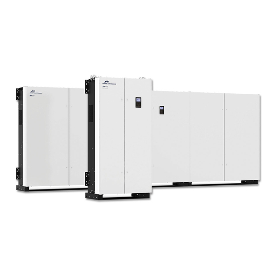
Power Electronics SD750 Accesories Manual
Optical fiber board
Hide thumbs
Also See for SD750:
- Hardware and installation manual (112 pages) ,
- Accessories manual (42 pages) ,
- Manual (32 pages)
Table of Contents
Advertisement
Quick Links
Advertisement
Table of Contents

Summary of Contents for Power Electronics SD750
- Page 1 SD750 ACCESORIES MANUAL OPTICAL FIBER BOARD LOW VOLTAGE VARIABLE SPEED DRIVE...
- Page 3 Accessories Manual Optical fiber board Edition: February 2022 SD75MA07DI Rev. D...
-
Page 4: About This Manual
Power Electronics SD750 variable speed drives. The optical fiber board is optional for the SD750 variable speed drives frame 1 to 8. In the case of the SD750 frame 9 to 11, it is included on the standard equipment and it would be along with the module connection kit. - Page 5 Commissioning. The equipment and technical documentation are periodically updated. Power Electronics reserves the right to modify all or part of the contents of this manual without previous notice. To consult the most updated information of this product, you may access our website www.power-electronics.com, where the latest version of this manual can be downloaded.
-
Page 6: Table Of Contents
INTRODUCTION ............................. 7 Optical fiber board specifications ......................7 LED indicator and optical fiber connectors ................... 8 Module connection kit (SD750 frames 9 to 11) ..................9 CONNECTIONS ............................ 11 Connection to the drive ........................11 Connection between modules ......................12 Wire routing ............................ -
Page 7: Safety Symbols
POWER ELECTRONICS SD750 SAFETY SYMBOLS Always follow safety instructions to prevent accidents and potential hazards from occurring. In this manual, safety messages are classified as follows: Identifies potentially hazardous situations where dangerous voltage may be present, which if not avoided, could result in minor personal injury, serious injury or death. -
Page 8: Safety Instructions
For maintenance operations, follow the instructions from the Maintenance Manual. Power Electronics accepts no responsibility for any damages resulting from incorrect use of equipment. CAUTION Read carefully the Hardware and Installation Manual, the Maintenance Manual and all documentation related to the drive to guarantee its safe use and avoid the risk of personal injuries and damages to the equipment. -
Page 9: Introduction
…among others. Up to three optional boards can be connected, maximum two of the same type. This manual focuses on the optical fiber expansion board. This board is optional for the SD750 variable speed drives frame 1 to 8; in the case of the SD750 frame 9 to 11, is included on the standard equipment. -
Page 10: Led Indicator And Optical Fiber Connectors
SD750 POWER ELECTRONICS LED indicator and optical fiber connectors The optical fiber expansion board has four optical fiber connectors and one led indicator (status) that provides information about the board's power supply. It is green and its frequency changes according to the operating state of the system. -
Page 11: Module Connection Kit (Sd750 Frames 9 To 11)
SD750 Module connection kit (SD750 frames 9 to 11) As mentioned previously, the optical fiber board is sent by default with SD750 drives frames 9 to 11, and in this case a module connection kit will be provided as well. - Page 12 SD750 POWER ELECTRONICS FRAME WIRE FUNCTION DESCRIPTION UNITS LENGTH Transmission OPTICAL FIBER SYNCHRO Reception Transmission 2 x T8 OPTICAL FIBER COMMS Reception WIRE RS232/RS485 Transmission OPTICAL FIBER SYNCHRO Reception Transmission 3 x T8 OPTICAL FIBER COMMS Reception WIRE RS232/RS485 Transmission...
-
Page 13: Connections
For the variable speed drives frame 1 to 8, the optical fiber must be connected directly, via the sixteen- pin ID connector on the back, to any of the three expansion connectors on the central control board of the SD750 drive. COMPONENTS OF THE CONTROL BOARD DESCRIPTION Fiber communication terminals. -
Page 14: Connection Between Modules
For drives frame 9 to 11, the modules connection kit provided with the drive must be installed. Connection between modules Follow the next electrical schemes to connect up to 4 modules of Power Electronics SD750 variable speed drives. Connection of 2 modules... -
Page 15: Wire Routing
POWER ELECTRONICS SD750 Wire routing The image below shows how wiring should be routed for connecting the different modules. POINTS OF REFERENCE DESCRIPTION Fix with flanges the optical fiber wires to the notches located behind the cover. Then, lead the wires through the right pipe. -
Page 16: Commissioning
Configure the G19.1.1 Type of control based on the chosen control. Parameters setting The parameters that are activated once the board is connected are summarized below: NOTICE For more details about the Modbus address and value range, see the SD750 Drive Programming and Software Manual. Group 1: Options Set on... - Page 17 POWER ELECTRONICS SD750 Group 25: Master/Slave This group will appear when parameter [G1.9] is enabled. Set on Screen Range Function Defines the roll which the drive is going to take in the network. FUNC. DESCRIPTION The drive assumes the Master role within the local module (parallel...
-
Page 18: List Of Modbus Addresses
SD750 POWER ELECTRONICS List of Modbus addresses Configuration parameters The configuration parameters for the Profibus board are summarized below: Parameter Screen Address Range Modbus Range Access Disable G1.9 Master/slave config = Disable 40021 Enable Local Master Local Slave G25.1 Role = Local Slave... - Page 19 POWER ELECTRONICS SD750 Custom Modbus Custom Modbus directions (G20.2.x) come by default as detailed in the tables below. For more information on Modbus addresses, see the Software and Programming Manual for the SD750 drive. Master input (G20.2.1) Modbus Position Parameter...
-
Page 20: Faults And Warnings Mapping
FAULTS AND WARNINGS MAPPING This section displays new faults that will only be available if optical fiber expansion board is connected. Please refer to the full list of faults and warnings in the SD750 drives Software and Programming Manual. Description of fault list... - Page 22 24H TECHNICAL ASSISTANCE 365 DAYS A YEAR FIND YOUR NEAREST DELEGATION POWER-ELECTRONICS.COM/CONTACT/...


Need help?
Do you have a question about the SD750 and is the answer not in the manual?
Questions and answers